Search results
Query: resistor
Links: 69 | Categories: 1
Categories
-
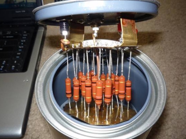 This will document a custom version of the K4EAA Dummy load done using 20 1K ohm 3 Watt Resistors, Piece of brass sheet, a quart paint can and a BNC connector
 -
 Building an End-Fed Half-Wave (EFHW) antenna from a kit, as detailed by Frank Bontenbal, PA2DKW, with process photos by Bob Inderbitzen, NQ1R, offers a practical approach for hams. This specific kit, a collaboration between ARRL and HF Kits, targets 10, 15, 20, and 40 meters, making it a versatile option for HF operations. Unlike a center-fed dipole, the EFHW is a half-wavelength antenna fed at one end, which simplifies deployment, particularly for portable use. The construction guide meticulously outlines the assembly of the 49:1 impedance matching network, crucial for transforming the antenna's high impedance (around 2,500 Ohms) to a transceiver-friendly 50 Ohms. Steps include preparing the enclosure by drilling holes for the coaxial connector and antenna connections, followed by the precise winding of enameled copper wire onto a toroid to create the transformer. The guide emphasizes careful insulation removal and soldering for reliable connections. Final assembly involves integrating a 100 pF capacitor for higher band compensation, soldering the transformer's primary and secondary sides, and conducting SWR tests with a 2K7 resistor or a half-wavelength wire. The document also provides examples of wire lengths for different bands, such as 16 feet for 10 meters or 66 feet for 40 meters, demonstrating the transformer's adaptability for various half-wavelength configurations.
 -
 Presents two distinct hardware modifications for the Icom IC-7300 transceiver, detailing the necessary steps for each. The first modification, a _MARS_ transmit expansion, involves the physical removal of specific surface-mount diodes (D422) from the main board, enabling transmit capabilities across a broader frequency range, including out-of-band frequencies. It specifies the diode location on US versions of the IC-7300 and suggests using small diagonal cutters if a soldering iron is not preferred or available. The second modification focuses on the internal antenna tuner, aiming to provide wider impedance matching capabilities. This involves adding a **100k ohm** resistor to a designated point within the tuner circuit. The resource also briefly mentions a microphone modification for the _HM219_ and a general power increase, though without specific instructions for the latter two. It emphasizes safety precautions, such as disconnecting power and inspecting the work area.
 -
 With high impedance earphones plugged into the audio jack on the Kenwood TS-590S or TS-590SG, you can hear a really annoying noise even with the AF volume set to zero. A simple quick-and-dirty solution is a resistor in series to the audio output.
 -
 This project outlines the construction of a simple TEFV (Tilted End-Fed Vertical) antenna suitable for backyard or park installations. The design requires basic materials such as 100 feet of coated stranded copper wire, wood stakes, metal ground rods, a non-conductive fiberglass pole, and essential tools like wire cutters and a soldering iron. The antenna is supported by a 20-33 feet tall pole and includes a 9:1 unun for impedance matching and a resistor for tuning. Step-by-step instructions guide the assembly, from preparing the wire and pole to connecting the unun and resistor, ensuring a functional and durable setup for outdoor use.
 -
 The document provides a detailed modification guide for the Zetagi HP201 SWR Wattmeter, converting it for HF amateur band usage. It replaces the original circuit with a Tandem Coupler based on the Sontheimer and Frederick directional coupler patent, enhancing accuracy and sensitivity. Key components include Murata toroid cores, scaling resistors, and a new calibration process. Challenges and solutions during the modification process are discussed, ensuring linear results across 160-10m bands. This guide also includes calibration instructions and theoretical insights into the coupler's operation.
 -
 This project describes the construction of a W3HH (T2FD) antenna for HF bands (3-30 MHz). While less efficient than a tuned dipole, it offers broad frequency coverage with a maximum SWR of 3.4 and reduces QRM (noise) significantly. On the 80-meter band, it shows slightly weaker signals than a dipole but with improved signal-to-noise ratio. The design includes non-inductive resistors, a 13:1 balun, and a "frog ladder" transmission line. Though not a high-performance antenna, it is compact and versatile, making it ideal for wide-band HF communication. Article in French
 -
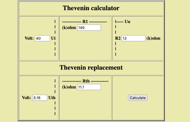 The Thevenin equivalent simplifies a complex circuit into an equivalent circuit with a voltage source and resistor for easy analysis of voltage and current at any point in the circuit. Use this online Thevenin calculator
 -
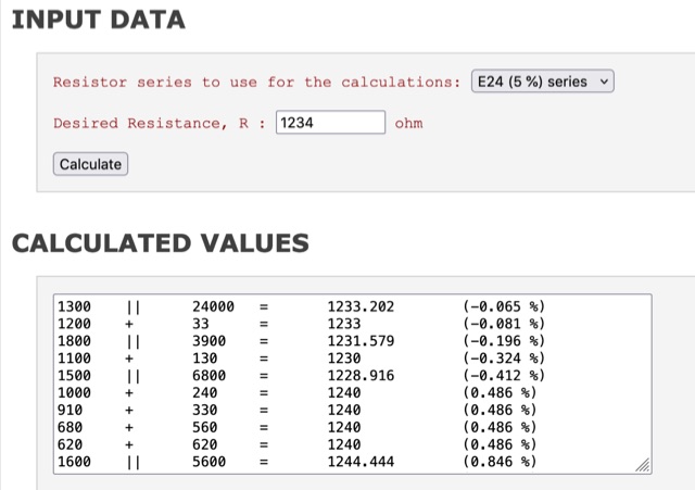 If you need a non-standard resistor value you could probably realize a close match using two resistor. If you use two resistor in series it is quite easy to figure out which values give the best match; on the other hand, using a parallel connection it is not so easy (at least for me) to find a good combination. This resistor calculation tool shows which combinations of two resistors (series or parallel) gives a match better than the closest standard value, for the E12 (10%), E24 (5%) and E96 (1%) series.
 -
 Elektrodump.nl is an online shop from the Netherlands specializing in amateur radio products. It offers a wide range of categories including antenna masts, antennas, tuners, coax connectors, and cables. The site also features broadcast equipment, electron tubes, semiconductors, and various electronic components like capacitors and resistors. Additionally, it provides measuring equipment, power supplies, and transmitters, catering to both hobbyists and professionals in the field of radio electronics.
 -
 The DIY Power Meter project utilizes the _INA226_ high-side power monitoring chip, paired with an ATtiny85 microcontroller, to measure voltage, current, and power, displaying the results on a 128x32 OLED screen. The INA226 communicates via an I2C interface and is programmed with a calibration factor based on the shunt resistance and current register LSB. The project is designed to handle a maximum current of 500mA using a 0.16ohm shunt resistor, which can be adjusted to a 0.2ohm resistor, reducing the full-scale current range to 409mA with a resolution of **12.5uA**. The shunt resistor dissipates only 33mW at maximum current, making 1/4 watt resistors suitable for the setup. The PowerMeter.ino sketch configures the shunt resistance and maximum design current, automatically calculating the calibration factor. The project can be prototyped on a breadboard using an Arduino Uno, employing the Wire library for INA226 and OLED communication, and the u8g2lib library for the OLED display. For the ATtiny85 version, the Adafruit-TinyWireM and Tiny4kOLED libraries are used. The power meter is independently powered by a 3V CR2032 cell, with power switching options including manual switches or DC switched jacks. The low-side n-channel MOSFET switch configuration is tested but introduces voltage drop issues, making manual switching a more reliable option until a suitable DC switched jack is found. DXZone Technical Profile: INA226 | ATtiny85 | OLED Display | Power Meter
 -
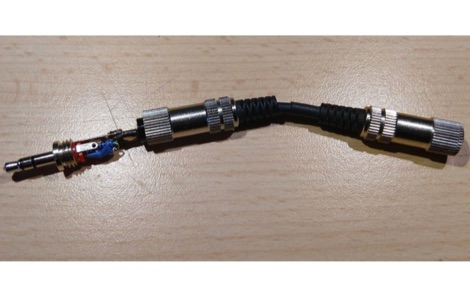
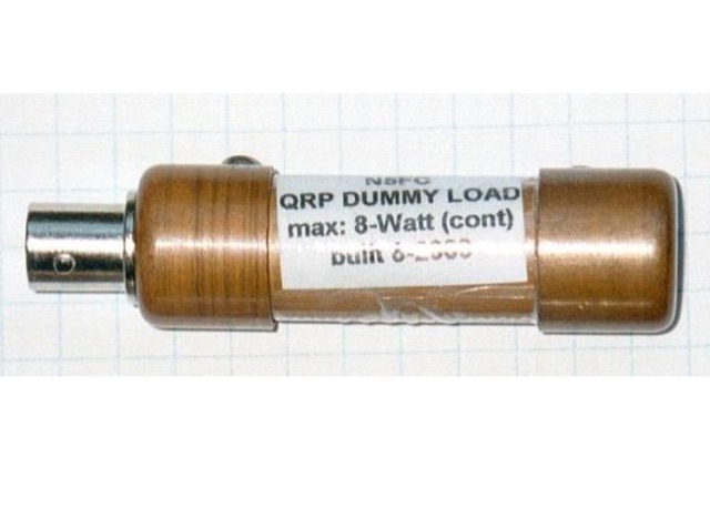 This is another variation on the parallel resistor, dummy load. It is perfect for QRP HF operation of 5-watts or less average power, and should be adequate for continuous operation at that level. It's light and compact, about 2-1/2 in length overall.
 -
 Make an otherwise fine radio even better, change one resistor and one capacitor in the audio section
 -
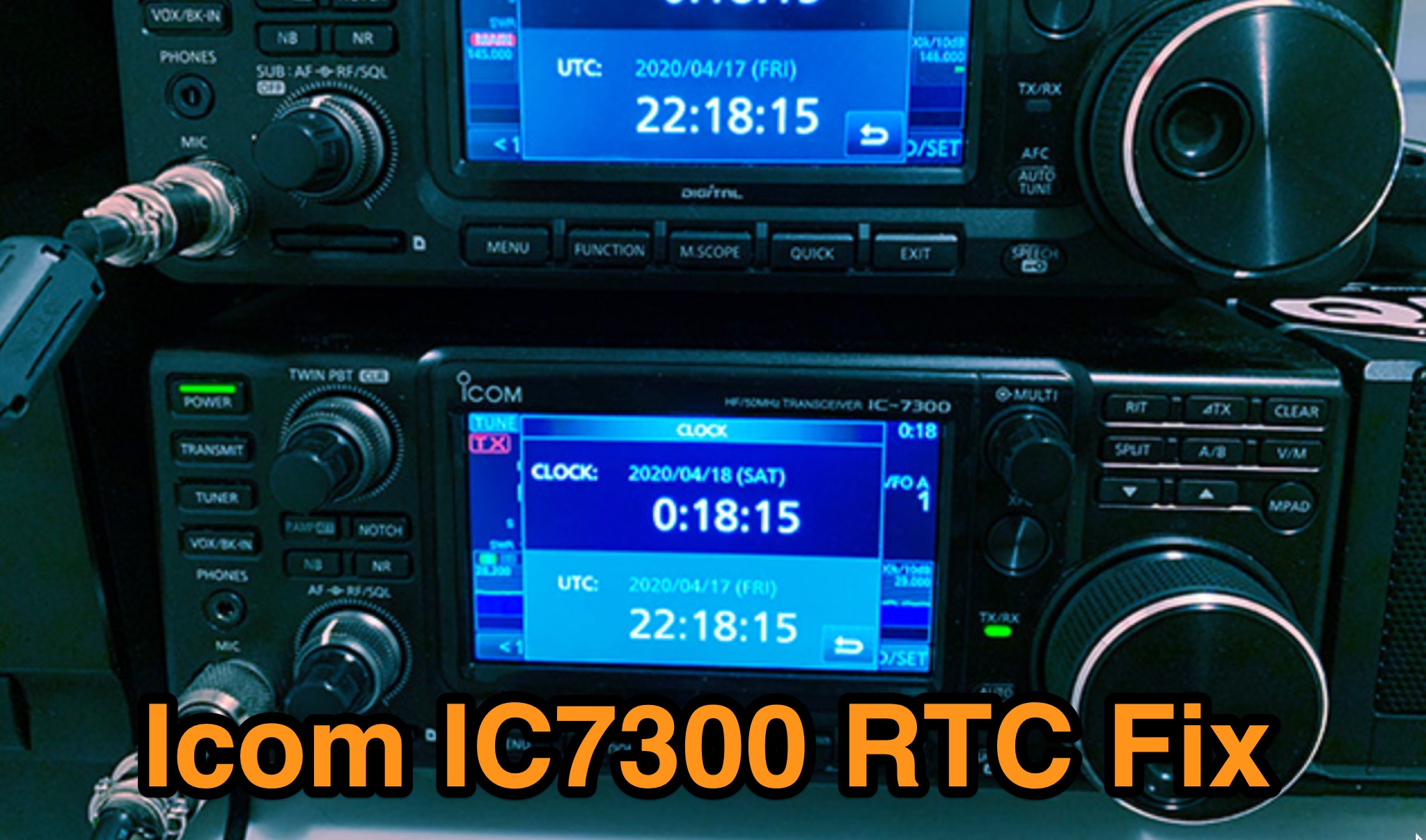 The article "Icom IC7300 RTC Fix" details the meticulous repair of an Icom IC-7300's faulty real-time clock (RTC). The author and a friend, Nacho, discovered the RTC was gaining an unacceptable 11 seconds per day. Investigations revealed the Seiko Epson RX8803LC RTC was far outside its specified stability. Despite replacing the RTC and a burned pullup resistor, the transceiver still malfunctioned, leading to the replacement of the processor. Post-repair, the clock's accuracy improved significantly, now gaining only 1.4 seconds per month. This narrative underscores the complexities of electronic repairs and the satisfaction of resolving intricate issues.
 -
 VE1ZAC's analysis details the performance of **MFJ927** and **SGC239** autotuners with portable HF vertical antennas, specifically comparing 31 ft and 43 ft configurations. The resource originated from challenges encountered during a Maritime QSO Party roving operation, necessitating a lightweight and easily deployable antenna system. Target bands for the contest included 80, 40, 20, 15, and 10 meters, with a maximum power handling of 100 W CW. The author utilized a 30-foot carbon fiber push-up pole to support a vertical wire element, noting its 2 lb weight and reliability. EZNEC modeling was employed to predict performance, showing favorable results for a 30-foot vertical with elevated radials, particularly on 40 and 20 meters. Feedpoint impedance measurements, taken with an AIM4170C, are presented for various HF bands, both with and without a 41-foot RG6 stub designed to reduce reactance on 80 and 20 meters. The stub significantly improved matching on these bands, easing the tuner's workload. Operational tests revealed issues with the MFJ927's reliability during contest setup, leading to reliance on the K3's internal tuner. The SGC239, tested post-contest, performed flawlessly. A detailed side-by-side comparison covers mechanical aspects, connection options, power bias, impedance range, board quality, and documentation. Modifications to the MFJ927, including a new aluminum case, white paint for heat reduction, and upgraded impedance-measuring resistors, are also described.
 -
 Twenty 1-watt carbon film resistors are configured in parallel to construct a 50-ohm **dummy load** for amateur radio applications. The design incorporates a heatsink for thermal dissipation and an **SO-239 connector** for RF input, making it suitable for QRP operations. This budget-friendly project details component selection, soldering techniques, and mounting procedures, achieving a continuous power rating of 10 watts and intermittent handling of up to 100 watts across HF and VHF frequency ranges. The resource provides a step-by-step guide for assembly. This construction offers an economical solution for essential shack tasks such as antenna tuning, transmitter testing, and SWR meter calibration without radiating an RF signal. The utilization of readily available components significantly reduces the overall build cost compared to commercial alternatives, providing radio amateurs with a functional and reliable test accessory. While specific VSWR measurements are not provided, the design prioritizes practical utility for low-power transceiver diagnostics and general RF experimentation.
 -
 The project details the construction of a GM3OXX OXO transmitter, designed to accommodate **FT-243 crystals** using 3D-printed FX-243 holders from John KC9ON. It presents specific frequency adjustments, noting a 7030 KHz HC-49/s crystal could be tuned from 7029.8 KHz to 7031.7 KHz with an internal 45pF trimmer capacitor. The build incorporates a modified keying circuit to prevent oscillator run-on key-up and includes a TX/RX switch for sidetone via a connected receiver, with the transmitter output routed to a dummy load on receive. Practical construction aspects are thoroughly covered, including the process of cutting a rectangular opening in a diecast enclosure for the FT-243 socket and the selection of a **low-pass filter** (LPF) based on the QRP Labs kit, derived from the W3NQN design. The author achieved approximately 800mW output power from a 14.75V supply, measured with an NM0S QRPoMeter, using a 16.5-ohm emitter resistor in the 2N3866 final stage. The article also touches upon the potential for frequency agility across the 40M band using multiple FX-243 units with various crystals. The narrative includes a brief diversion into Bob W3BBO's recent homebrew projects, such as his Ugly Weekender MK II transceiver, highlighting the enduring appeal of classic QRP designs. The author reflects on the personal satisfaction derived from building RF-generating equipment, irrespective of DX achievements, and shares experiences of making local contacts with the 800mW OXO transmitter on 40 meters.
 -
 The Pressure Paddle V2.0 simplifies the original 2019 design by using MOSFETs’ unique properties for reliable, minimalistic switching. When pressure sensors detect a press, they reduce resistance, activating the MOSFET and lowering voltage until it stabilizes at the MOSFET’s threshold. This ensures consistent “key down†signals for the transceiver. Compatible with 3-5V logic systems, the circuit operates independently of pull-up resistor size. The PCB is lightweight, easy to assemble, and can be packaged in heat shrink or mounted. This version maintains durability with fewer components and flexible packaging options.
 -
 Presents the CISAR Isola d'Elba (IQ5IN) club, detailing its role as a central point for local radio amateurs and enthusiasts. The club focuses on educational activities, technical experimentation, and fostering radio culture within the community. It provides resources for obtaining an amateur radio license, offers various didactic materials, and publishes technical articles. The IQ5IN section actively promotes a knowledgeable and engaged community, welcoming new enthusiasts through local events and practical guides. Recent content includes discussions on the role of radio amateurs during wartime, an in-depth analysis of electrical resistors from solid-state physics to RF applications, and a comprehensive guide to the UHF amateur band in Italy, covering its characteristics and uses.