Search results
Query: rf switch
Links: 87 | Categories: 0
-
 MikroTik is a Latvian company which founded in 1995 to develop routers and wireless ISP systems. Wifi Routers, router boards, switches, interfaces and enclosures.
 -
 A 0-30 MHz step attenuator, constructed from switchable Pi attenuation pads, provides a practical tool for evaluating receiver sensitivity and calibrating S-meters. The design utilizes readily available 5% tolerance resistors, with values derived from paralleled components to achieve specific attenuation steps. A schematic (Fig 1) illustrates the circuit, including PCB pad shielding, while a table details required and actual resistor values, along with percentage differences. Measurements of voltage input versus output at various frequencies are used to calculate dB attenuation, presented in a graph (Fig 4). The resource includes formulas for determining output voltage from a known input and a comprehensive 0-40 dB voltage multiplier table, which is crucial for precise signal level management. The project also references external attenuator calculators and equations for further study. Photos (1-3) provide visual guidance for the assembled unit, showing bottom, top, and front views. The project emphasizes the use of **Pi attenuation pads** and **receiver sensitivity** evaluation, offering a hands-on approach to RF signal management.
 -
 Operating in a Single Operator Two Radios (SO2R) setup, especially with beverage antennas, often exposes the receiving radio's front-end to significant RF energy from the transmitting radio. This resource details a practical, homebrew receiver protection circuit designed to mitigate this risk. The core of the design involves a non-inductive 2W 22 Ohm carbon composition resistor in series with the RX antenna line, followed by two stacks of four fast-switching diodes (e.g., _1N914_) configured in opposite polarizations. This arrangement effectively clamps the incoming voltage to approximately 2.8 V peak-to-peak, safeguarding sensitive receiver input components. The series resistor plays a crucial role by absorbing excess power, preventing the diodes from exceeding their current ratings and potentially failing open, which would leave the receiver unprotected. The author, _N4KG_, measured up to 50 watts of coupled power between 80M slopers on the same tower, highlighting the necessity of such protection. The design is presented as a cost-effective solution to prevent damage to receiver input transformers, with the author noting successful protection of a receiver even after a resistor showed signs of overheating. This simple circuit can be integrated via a transverter plug, offering a robust defense against high RF input.
 -
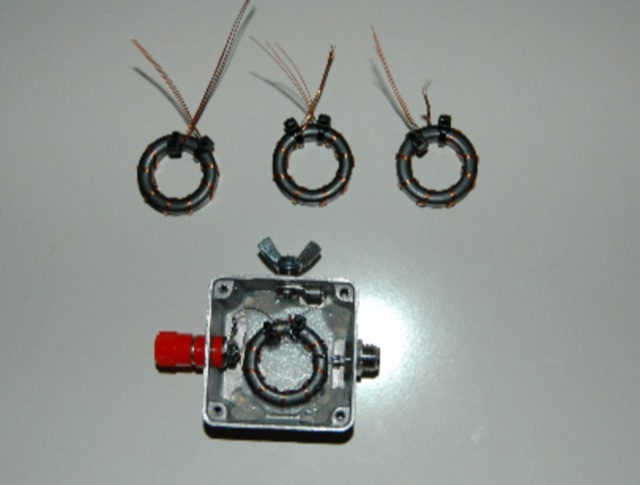
 No matching adjustments needed. Directly perfect match to 50 Ohms using a remotely switched wideband transformer
 -
 Constructing a dual-band antenna for 40 and 20 meters often involves compromises in size or complexity. This resource presents a compact _open sleeve dipole_ design that addresses these challenges by using 450-ohm ladder line and folded elements to achieve a total length of approximately **17.17 meters**, significantly shorter than a full-size 40-meter dipole. The design leverages electromagnetic coupling, where a primary radiator handles the 40-meter band, and a second conductor resonates on 20 meters without direct electrical connection. This configuration eliminates the need for traditional traps, loading coils, or switching components, simplifying construction and reducing potential loss points. The antenna is fed with RG-58C/U coaxial cable, and a common-mode choke is recommended at the feed point to suppress sheath currents, ensuring a cleaner radiation pattern and minimizing RF in the shack. The design is well-suited for portable operations, field deployments, temporary installations, and restricted urban environments where space is a premium, offering solid performance on both HF bands.
 -
 Operating in antenna-restricted communities presents unique challenges for amateur radio operators, often necessitating creative solutions for antenna deployment. This resource details the design and implementation of stealth antennas within a townhouse community in Exton, PA, where external antennas were strictly forbidden by covenants. The author, WB5NHL, describes his setup, which involved locating the shack in the basement and utilizing an unused space under the roofline of a finished third-floor loft for antenna placement. The content specifically addresses the practicalities of routing coax cables three floors and maximizing antenna performance within limited attic space. It covers solutions for multi-band operation, including dedicated sections for 40-10 meter and 80-meter antennas, along with strategies for mitigating potential interference issues. The approach emphasizes full compliance with community covenants, achieving maximum height-above-ground for horizontal antennas, enabling instant band switching, and efficiently utilizing available attic volume. While acknowledging limitations such as potential interference with high power and fixed antenna patterns, the resource provides a detailed account of a functional compromise for restricted environments. Links to individual pages on _coax cables_, _40-10 meter antennas_, _80-meter antennas_, and _interference issues_ offer deeper dives into each specific aspect of the installation.
 -
 HAM-made engineering products supplies and produces coaxial relays, antenna switches, sequencers, roller inductors, variable capacitors, low noise preamplifiers, RF power rotary switches and coil bodies.
 -
 This article describes a simple yet effective multi-band vertical HF antenna design that performs exceptionally well across 80m to 10m bands. The antenna consists of a 13.4m wire mounted on a 12.4m Spiderpole, complemented by four 12m radials and a ground rod. Initially tuned with a manual LC circuit, it was later upgraded with a CG3000 remote auto ATU for convenient band switching. Despite antenna modeling software suggesting limited performance on higher frequencies, the system demonstrated excellent DX capabilities across all bands, outperforming more complex vertical antenna designs.
 -
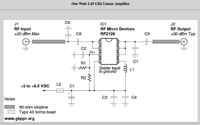 This will show you how to add a RF power amplifier to your Proxim Symphony for under $50. The cost is reduced by using the existing components on the Symphony, such as the PIN diode switch, and just inserting a higher power final amplifier. Increase the RF output power of your wireless network card to 1 Watt.
 -
 A dual band X-frame wire antenna made using 4 turns for response down to 3 MHz or so, and 2 turns (switched) for response up to around 18 MHz. The loop configurations are tuned using common eBay 365 pF tuning caps.
 -
 An Arduino Based Antenna Switch For The IC-7300 that monitors the band voltage from the rear accessory socket on the IC-7300. Two RF antenna relays are used to switch to the appropriate output.
 -
 A comprehensive overview of a 10-band attic antenna system developed for contesting and DXing is presented, covering its evolution and performance. Initially intended in a restricted location, the system has been developed through numerous iterations, using various antenna types such as delta loops and Yagis. Automatic switching, dual-direction capability, and optimum tuning for certain band segments are among the most notable features. The project not only improves operating efficiency but also provides great learning opportunities in antenna design and installation in restricted places.
 -
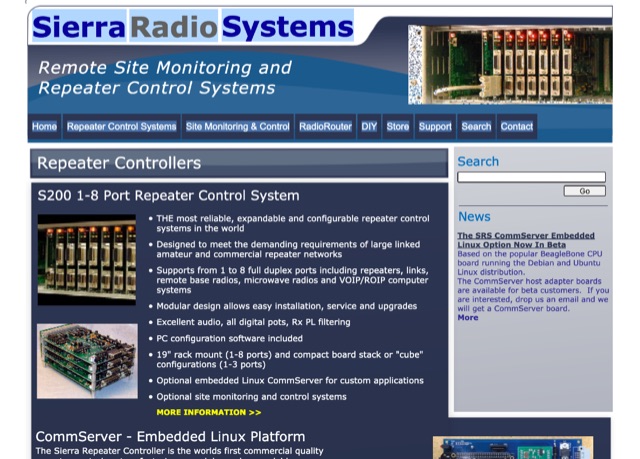 Sierra Radio Systems site controllers are used to monitor and control remote radio and equipment sites, often implemented to monitor repeater systems, broadcast equipment, solar power infrastructure, tracking rf power, temperature, voltage, current and switch closure
 -
 This innovative antenna tuning unit (ATU) enables QRP operators to match their antennas without transmitting RF signals. Using a noise bridge technique instead of traditional transmit-and-tune methods, it achieves truly silent operation. The design incorporates an L-match network with switched inductors and variable capacitor, handling impedance matching from 3-30MHz. Operating from a 9V battery, it includes a built-in RF power meter and dummy load for QRP transmitter testing. The compact unit is particularly suitable for portable operations where minimal RF emissions during tuning are desired.
 -
 A home made Beverage system for portable use. The goal was to switch between 4 single Beverage antennas without interfering on the other receiving stations.
 -
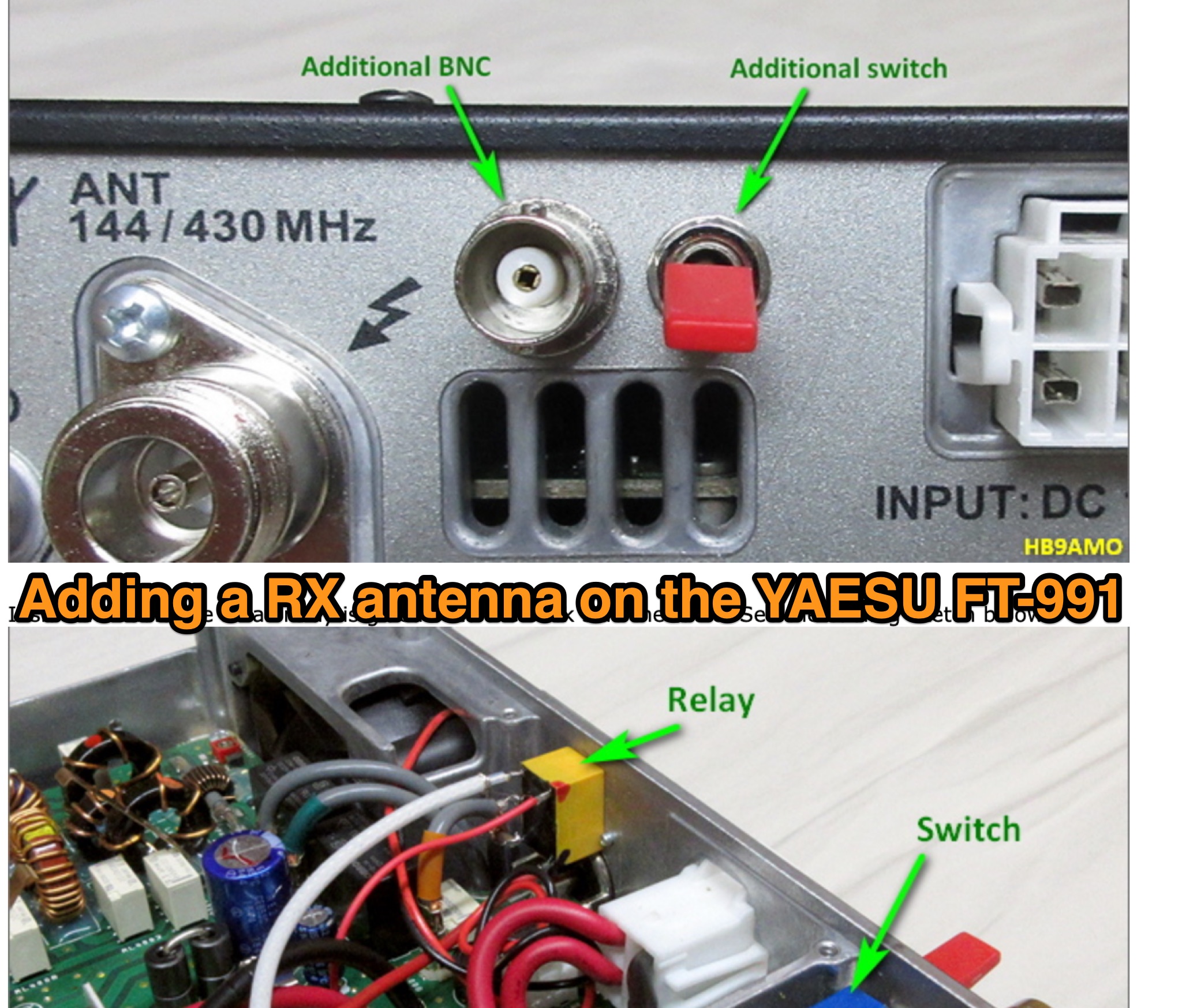 The FT-991 is a nice small size and lightweight radio, it is perfect for portable operations. It can be carried along with a laptop computer as hand luggage in airplane. The weak point of this radio, is it does not have a separate RX antenna capability. Therefore i decided to add this feature. On the back side of the radio a BNC connector is added to connect the RX antenna and a switch is fitted to select between RX antenna or main antenna.
 -
 Showcasing German engineering, ANjo Antennen develops and manufactures a diverse portfolio of amateur radio and commercial antenna products. Their offerings span a wide frequency range from 1.8 MHz to 3000 MHz, emphasizing electrical and mechanical precision for longevity. The company actively participates in events like FUNK.TAG Kassel, providing opportunities for direct engagement and order pickup. ANjo's product line includes high-performance **Yagi antennas** optimized for Tropo and EME, along with multi-stacked Quad antennas designed for contest operations, featuring wide horizontal and narrow vertical beamwidths. They also produce circularly polarized satellite antennas, some with switchable LHCP/RHCP, leveraging their commercial satellite antenna expertise. Beyond amateur applications, ANjo provides flexible, custom antenna solutions for commercial sectors such as BOS, EMC measurements, and telemetry. Their commitment to quality is evident in the Premium-Line antennas, which utilize **1.4301 (V2A) stainless steel** for mast clamps and connectors, ensuring durability and corrosion resistance. They also offer end-fed HF multiband wire antennas, known for their compact footprint and discreet installation.
 -
 This article details the author's process of designing and building a trap dipole antenna for the 17, 12, and 6-meter amateur radio bands using a Yaesu FT-450 transceiver. The antenna incorporates parallel-tuned circuit traps to enable operation across multiple bands without switching aerials. Key construction details, including coil and capacitor specifications, are discussed, along with the testing results, which include successful long-distance communications on the 50 MHz band. The article highlights the flexibility of home-built antennas and provides insights for amateur radio enthusiasts looking to optimize multi-band performance.
 -
 This article details the design and construction of a compact 20-meter QRP SSB transceiver by Pete Juliano, N6QW, measuring just 2 x 4 x 2 inches—small enough for a shirt pocket. Inspired by a 1963 QST design and refined from a prior version, it employs bilateral circuits, a 4.9152 MHz homebrew crystal filter, switched-crystal VXO for 60 kHz coverage (14.160-14.220 MHz), and standard components like ADE-1L mixers and IRF510 PA for 1W output. Key innovations include a double-sided PCB skeletal frame for shielding and isolation, Vectorboard sub-assemblies, and ultra-miniature relays. The bilateral receiver/transmitter shares stages, omitting AGC for simplicity, while a W3NQN LPF and optional 10W external amp enable DX contacts. Tune-up focuses on crystal matching and bias for linearity. Videos on YouTube demonstrate performance, confirming excellent stability and audio. Total cost nears $100, prioritizing portability over features like CW.
 -
 The POCKET TUNER V1.1 is a highly compact HF T-Match antenna tuner designed for QRPp and QRP portable operations. With a credit card-sized form factor, it is tailored for low-power setups, supporting HF bands from 10m to 40m. The tuner features a unique design using rotary switches for precise capacitor adjustments, allowing tuning in small increments. Its inductance selection is optimized for various bands, ensuring efficient performance. Equipped with a resistive tuning indicator, it protects the transmitter by reducing SWR during adjustments. This versatile and portable tuner is ideal for field operations, enabling efficient antenna matching for low-power rigs.
 -
 Integrating a _Software Defined Radio_ (SDR) into an existing ham radio setup involves connecting it with a standard transceiver (TRX), power amplifier (PA), and antennas. The core component is a splitter box that facilitates the connection between the TRX and the SDR, allowing for simultaneous operation without modifying existing equipment. In receive mode, the splitter ties the antenna inputs of both the TRX and a direct conversion receiver (DC RX) together. During transmission, the DC RX input is grounded via a fast telecom relay controlled by the transceiver's -SEND signal, incorporating a 10ms delay for safety. The splitter box includes a 3.7 dB input attenuator for impedance matching and acts as a protective fuse for the DC RX input. Ground loops are mitigated using common mode balun transformers, while the DC RX input is insulated with a broadband transformer. An audio switch box complements the setup, enabling users to listen to either the main transceiver, the SDR output, or both simultaneously. This configuration ensures noise immunity and safety, with the splitter housed in a screened box made from PCB material. On-air tests, such as the CQ WW 160m CW DX Contest, demonstrate the system's effectiveness, showcasing the SDR's ability to handle crowded band conditions with superior selectivity and dynamic range. The SDR's narrow bandwidth filters and waterfall display provide significant advantages, allowing operators to detect weak signals amidst strong interference. The integration of SDR with conventional radios offers enhanced operational flexibility and performance in challenging environments.
 -
 The DIY Power Meter project utilizes the _INA226_ high-side power monitoring chip, paired with an ATtiny85 microcontroller, to measure voltage, current, and power, displaying the results on a 128x32 OLED screen. The INA226 communicates via an I2C interface and is programmed with a calibration factor based on the shunt resistance and current register LSB. The project is designed to handle a maximum current of 500mA using a 0.16ohm shunt resistor, which can be adjusted to a 0.2ohm resistor, reducing the full-scale current range to 409mA with a resolution of **12.5uA**. The shunt resistor dissipates only 33mW at maximum current, making 1/4 watt resistors suitable for the setup. The PowerMeter.ino sketch configures the shunt resistance and maximum design current, automatically calculating the calibration factor. The project can be prototyped on a breadboard using an Arduino Uno, employing the Wire library for INA226 and OLED communication, and the u8g2lib library for the OLED display. For the ATtiny85 version, the Adafruit-TinyWireM and Tiny4kOLED libraries are used. The power meter is independently powered by a 3V CR2032 cell, with power switching options including manual switches or DC switched jacks. The low-side n-channel MOSFET switch configuration is tested but introduces voltage drop issues, making manual switching a more reliable option until a suitable DC switched jack is found. DXZone Technical Profile: INA226 | ATtiny85 | OLED Display | Power Meter
 -
 The Acom 1500 HF+6M Linear Amplifier is a high-quality and user-friendly amplifier that provides excellent performance and reliability. G6NHU, who previously owned an Acom 1000, upgraded to the Acom 1500 after nine years and has been using it for about eighteen months. Key features highlighted include the ability to connect three antennas internally, straightforward tuning process, robust construction that can handle high SWR, quiet operation, fast and quiet switching for efficient CW operation, and clean output signal even when driven hard. G6NHU highly recommends the Acom 1500 and states they would not hesitate to purchase another one in the future.
 -
 The Aziloop DF-72 antenna system provides 72 K9AY headings and 36 loop axes, allowing for rapid switching in 60 ms. It integrates a switchable 18 dB preamp, a 4-step attenuator (0-18 dB), and four 7-pole preselection filters to optimize receiver performance. The K9AY load is adjustable from 250 Ohm to 950 Ohm in 50 Ohm increments, offering flexibility for various receiving conditions. Control is managed via an intuitive Windows UI, supporting Local, Client, or Server modes, with headless remote operation possible through the built-in Ethernet Server. _Omni-Rig_ support facilitates auto-filter selection, PTT muting, and Rig-Sync functionality, enhancing integration with existing station setups. Designed by _GW4GTE_, the system utilizes a low visual impact, small-footprint antenna with orthogonal loops and an earth connection. It is suitable for general monitoring, co-channel station resolution, basic direction finding, and interference reduction across the VLF to HF spectrum.
 -
 This article from the July 1976 issue of Radio REF discusses the trend of large antennas for ham radio operators on the low bands. It specifically focuses on a Yagi 2 element antenna for the 80m band, detailing its construction and functionality. The author explains how the antenna can be switched between directing signals towards the West or East using a switch at the station. The article also provides technical details on the lengths of the director and reflector elements, and how they impact the antenna's performance. A useful resource for hams looking to build or understand Yagi antennas for the 80m band.
 -
 This article discusses the design and implementation of a 2-element wire beam antenna for the 20 meter band, suitable for field day operations with 4 Switchable Directions. The antenna is configured with sloped wires in an inverted V shape, with a specific design to achieve directional properties. The author tested the antenna design using MMANA and NEC2 software, based on a solution published in QST. Detailed diagrams and instructions are provided for constructing the antenna on top of a 12 meter mast, with specific wire lengths and positioning to ensure optimal performance. This resource is valuable for hams looking to build a directional antenna for the 20m band and improve their field day setup.
 -
 This paper presents an 80 meter wire 3-element beam antenna in an inverted-V configuration, designed for limited-height towers. Using EZNEC modeling, the antenna features a central parasitic reflector and two switchable driven elements at each end, enabling NE/SW coverage without moving parts or networks. Element lengths are optimized for SSB (3.8 MHz) and CW (3.5 MHz) operation, with a 50 Ω feed and rope-supported boom. The design delivers high gain, effective takeoff angles, and excellent reception, confirmed in real-world DX contest operation. Its simplicity, reliability, and ease of construction make it ideal for operators seeking performance without complex matching systems.
 -
 This resource presents a non-rigorous evaluation of the front-to-back (F/B) ratio of short Beverage antennas, specifically designed for low-band operation on frequencies such as 160, 80, 40, and 30 meters. The author, VE1ZAC, details the methodology used to measure the F/B ratio, which involves using a Millen Grid Dip Oscillator as a portable signal source. Measurements were taken by switching the antenna direction and recording S Meter and preamp readings to derive gain numbers. The document discusses the challenges faced in achieving accurate measurements and the assumptions made during the process, such as the calibration of S Meter units at 6 dB. This evaluation is particularly relevant for amateur radio operators interested in antenna performance on low bands.
 -
 After years of reliable performance, a 26-year-old Icom 706MK2G exhibited an unusual deviation during FM transmission, with the actual frequency being 10kHz off from the displayed frequency. Additionally, the power meter showed a sharp dip during transmission. Upon investigation, it was discovered that the FM VCO voltage adjust variable had become dirty and sluggish over time. By adjusting the variable capacitor and cleaning it with switch cleaner, the issue was resolved, restoring stable power output and accurate frequency transmission.
 -
 The project details the construction of a GM3OXX OXO transmitter, designed to accommodate **FT-243 crystals** using 3D-printed FX-243 holders from John KC9ON. It presents specific frequency adjustments, noting a 7030 KHz HC-49/s crystal could be tuned from 7029.8 KHz to 7031.7 KHz with an internal 45pF trimmer capacitor. The build incorporates a modified keying circuit to prevent oscillator run-on key-up and includes a TX/RX switch for sidetone via a connected receiver, with the transmitter output routed to a dummy load on receive. Practical construction aspects are thoroughly covered, including the process of cutting a rectangular opening in a diecast enclosure for the FT-243 socket and the selection of a **low-pass filter** (LPF) based on the QRP Labs kit, derived from the W3NQN design. The author achieved approximately 800mW output power from a 14.75V supply, measured with an NM0S QRPoMeter, using a 16.5-ohm emitter resistor in the 2N3866 final stage. The article also touches upon the potential for frequency agility across the 40M band using multiple FX-243 units with various crystals. The narrative includes a brief diversion into Bob W3BBO's recent homebrew projects, such as his Ugly Weekender MK II transceiver, highlighting the enduring appeal of classic QRP designs. The author reflects on the personal satisfaction derived from building RF-generating equipment, irrespective of DX achievements, and shares experiences of making local contacts with the 800mW OXO transmitter on 40 meters.
 -
 An Arduino-based interface provides a remote tuner call command for Icom **IC7700** and **IC7800** transceivers, addressing the lack of a built-in function for external tuners such as the MFJ 998RT. This setup initiates a low-power transmit signal, typically 15 watts, allowing the remote autotuner to perform its matching sequence. The article details the required CI-V line communication and modifications to existing Arduino code, specifically referencing contributions from Jean-Jacques ON7EQ for improved Icom interrogation routines. The system involves a sequence of steps: storing the transceiver's current mode and power, disabling the internal autotuner, activating a control relay to interrupt the amplifier line, switching to RTTY mode at low power, and initiating transmit. The transmit duration is manually controlled by the operator, observing the SWR meter until a low SWR is achieved, then a second button press stops the transmission. A built-in 4-second transmit limit provides a safety measure. After tuning, the routine restores the original mode and power settings, re-enables the internal autotuner, and performs a brief 2-second RTTY transmission for internal tuner adjustment. The circuit diagram includes a Panasonic form 2 relay for amp control and emphasizes critical delays in the Arduino code for stable operation at 9600 baud CI-V communication. Compatibility with logging software like DXLab, N1MM, and N3FJP is noted, with specific interrogation time settings required to avoid conflicts.
 -
 This online project documentation details the construction of a hands-free microphone interface unit designed for _mobile_ amateur radio operation. The curriculum covers the integration of electret microphone elements with amateur radio transceivers, specifically addressing **VHF** band communication. It outlines the circuitry for a switch box that provides an interface between various radio models and microphone types. The guide specifies the inclusion of a **1750 Hz** tone-burst generator for accessing amateur radio repeaters, an operational protocol for many VHF systems. Design considerations include the reduction of ambient vehicle noise through an adjustable audio input level control. The project provides schematics and wiring diagrams for connecting the interface unit to specific amateur radio transceivers, including the Yaesu FT-817. It addresses the selection and adaptation of readily available electret microphone and earpiece assemblies, initially sourced from mobile phone accessories, and later from dedicated headset units. The design incorporates a control mechanism for radio functions, enabling hands-free operation during _mobile_ excursions. Circuit details cover power supply considerations for the electret microphone and signal routing for both transmit audio and received audio monitoring. The documentation specifies component selection for the switch box, ensuring compatibility with common amateur radio microphone input impedances and output levels. This includes considerations for PTT line switching and audio path isolation. DXZone Focus: Online Project Documentation | Hands-Free Mobile Microphone Interface | Electret Microphone Integration | 1750 Hz Tone-Burst Generation
 -
 This resource details **cooling modifications** for Ameritron AL82, AL1200, and AL1500 HF amplifiers, specifically addressing heat issues encountered during high-duty-cycle digital mode operation. The author, WD4NGB, observed excessive heat in the tank area and band switch on an AL82, attributing it to insufficient exhaust over the 3-500 tubes and a complete lack of exhaust over the tank area. The modifications aim to prevent common failures such as damaged band switches and deformed insulating materials by increasing airflow and exhaust area. The page describes adding five holes to the chassis for enhanced cooling to the band switch and tank area, alongside enlarging the exhaust area over the inner 3-500 tube and the tank area on the amplifier cover, utilizing expanded metal for safety and RF shielding. The original cover featured 26.25 square inches of exhaust; the modified version significantly increases this to 48.5 square inches over the tubes and introduces an additional 15 square inches over the band switch. These changes are intended to resolve heating problems encountered during heavy, 100% duty cycle use in modes like RTTY or long SSB contests, which typically generate substantial heat. The article also discusses upgrading to a higher output fan, such as the G2E085-AA05-21, and modifying tube sockets for improved airflow and reduced back pressure, citing Tom Rauch (W8JI) of CTR Engineering as a source for parts.
 -
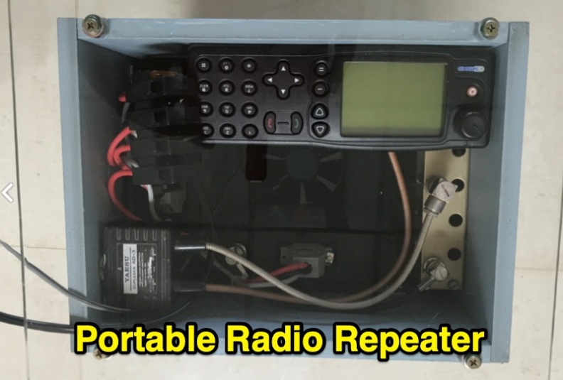 Demonstrates the construction of a portable 2-meter repeater system utilizing a **Yaesu DR-1X** transceiver, configured for both analog FM and C4FM digital voice operation. The design emphasizes portability, robustness, and effective thermal management, incorporating a "wind tunnel" airflow system with a fan to maintain transmit module temperatures at 38 degrees Celsius during continuous operation. The system integrates a diplexer, control head, and is housed in a compact, lightweight case weighing under 8kg, designed for single-person deployment. Covers practical considerations for field deployment, including power sources, antenna types, and the overall system architecture for public service events and emergency preparedness. The resource details the modular "wrap around" construction, showing how components like thermal switches for fan control and Anderson Powerpole connectors are integrated. It highlights the system's ability to provide reliable communications support for club activities and emergency communications.
 -
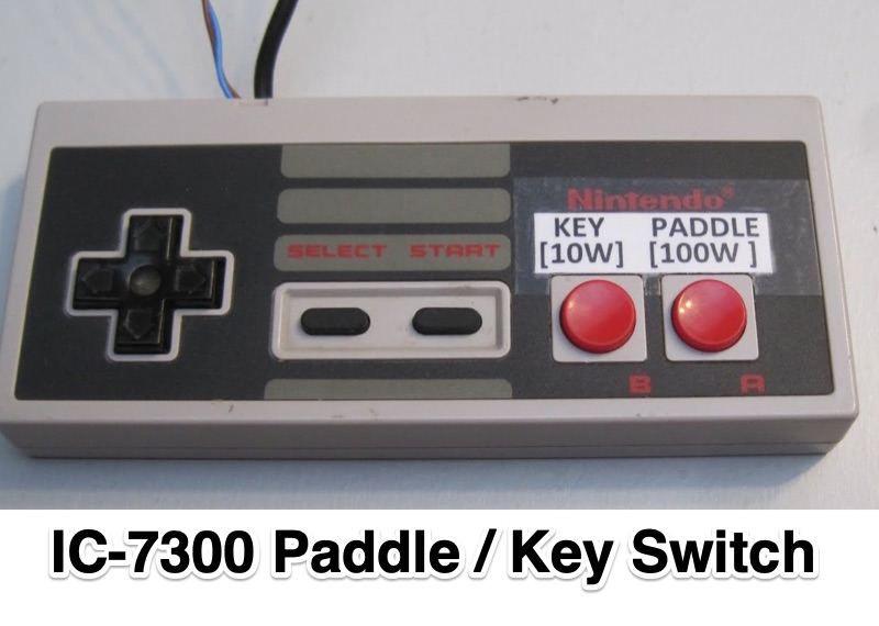 Demonstrates an **Arduino-based** solution for the Icom IC-7300 transceiver, specifically addressing the operational inconvenience of switching between a CW paddle and a straight key. The project leverages the IC-7300's **CI-V bus** (Computer Interface 5) to provide instant keyer type selection and two preset power levels, bypassing the rig's menu system which otherwise requires eight button presses. This implementation utilizes the 3.5mm CI-V connector, leaving the USB port free for CAT control and the internal soundcard, a critical design choice for integrated station setups. The system's utility is particularly evident for CW operators who frequently alternate between keying methods during contesting or general operating. The article details the hardware setup, including an Arduino Nano, a 3.5mm jack for CI-V, and pushbuttons for control. An update in 2023 expanded the project to incorporate an 8-button Nintendo controller, enhancing user interface flexibility and demonstrating the adaptability of the initial design for further customization and feature integration.
 -
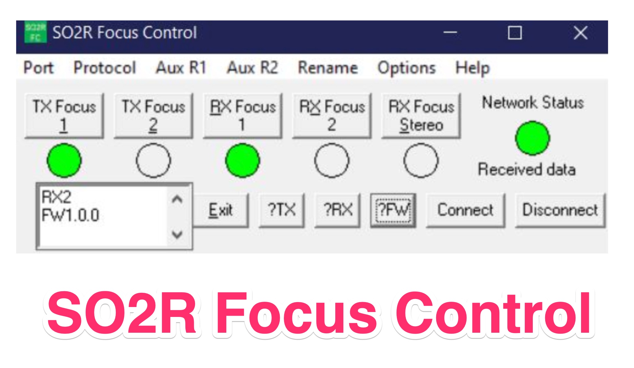 SO2R Focus Control and SO2R FC Server are freeware VB6-based tools enabling remote or local control of modern SO2R controllers (supporting OTRSP and MK2R protocols) outside contest logging sessions. The client (SO2R Focus Control) manages serial-connected controllers and can interface remotely via LAN or internet using the optional SO2R FC Server, which supports up to two concurrent clients. Key features include AUX port control with customizable labels, interlock options, AES-256 encrypted network communication, and compatibility from Windows XP through Windows 11. Designed for operators needing flexible station control—especially for remote antenna switching—both programs install cleanly via NSIS and uninstall completely.
 -
 Demonstrates a LoRa APRS Tracker project featuring a comprehensive menu system for message management, weather requests, and monitoring nearby trackers. The device supports adjustable display eco mode and screen brightness, optimizing power consumption by dynamically changing processor speed from 240MHz to 80MHz. GPS beacons are encoded for efficient RF transmission, and an OLED screen displays altitude, speed, course, _BME280_ weather data, or new message counts, along with recently heard stations. Bluetooth connectivity enables operation as a TNC with Android (APRSdroid) or iPhone (APRS.fi app), providing LED and sound notifications for transmissions and received messages. The integrated BME280 module facilitates weather data display and transmission, with Winlink mail support via _APRSLink_. The tracker can switch between **three major LoRa APRS frequencies** worldwide, offering versatile global operation.