Search results
Query: schema
Links: 260 | Categories: 72
Categories
- Antique Radios > Schematics
- Antennas > Baluns > 1 to 1 Balun
- Antennas > 20M > 20 meter Vertical Antennas
- Antennas > Baluns > 4 to 1 balun
- Operating Modes > Amateur Television
- Technical Reference > Amplifiers
- Technical Reference > Antenna Rotator
- Technical Reference > Antenna Switch
- Technical Reference > APRS
- Technical Reference > Attenuators
- Technical Reference > ATV
- Technical Reference > Audio
- Technical Reference > Beacon keyers
- Radio Equipment > HF Vertical Antenna > Butternut HF2V
- Antennas > Capacitive
- Technical Reference > Components
- Technical Reference > Receivers > Crystal radio
- Technical Reference > Digital ATV projects
- Radio Equipment > Receivers > Drake R-4B
- Technical Reference > DTMF
- Technical Reference > Dummy Loads
- Technical Reference > Duplexers
- Antennas > EH
- Antennas > End-Fed > End Fed Half Wave Antenna
- Technical Reference > Frequency Counter
- Antennas > HB9CV
- Technical Reference > Headsets and Speakers
- Technical Reference > HF Radios
- Technical Reference > Homebrew
- Antennas > Horn
-

-
-
 An android app to remotely control your Yaesu FT 857 817 897 using a common Bluetooth CAT interface. Schematic provided.
 -
-
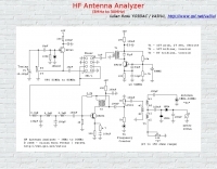 3 to 30 Mhz antenna analyzer schematic by YO3DAC / VA3IUL
 -
 Sams Photofact downloads - Schematics and Service Manuals for Radios, Amplifiers, More
 -
 Advanced QRP Low Cost Mosfets HF Linear Amplifier with schematics, IMD, gain data and more. Six articles about amateur radio.
 -
 This Magnetic Longwire Balun (MLB) makes it possible to efficiently use a coaxial lead-in cable with all forms of longwires, T-forms or other types of wire antennas, without the need for an antenna tuner.
 -
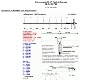 ON6MU Optimized 10 and 6 and 4 element UHF Yagi Antenna
 -
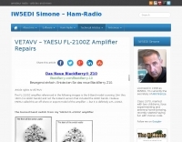 The FL-2100Z amplifier referenced in the following images is the 6-Band model covering 10m thru 160m (no WARC bands) and not the 9-Band version that included the WARC bands. Modifications, schematics and manual
 -
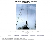 A Versatile Innovative Portable Multi-band Tunable Antenna can work HF VHF and UHF ideal as portable or balcony antenna
 -
 RF Choke to prevent hf currents on the feedline. This Magnetic Longwire Balun (MLB) makes it possible to efficiently use a coaxial lead-in cable with all forms of longwires, T-forms or other types of wire antennas, without the need for an antenna tuner.
 -
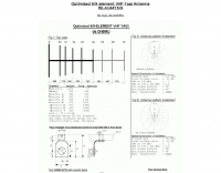 ON6MU optimized 6/9 element vhf yagui antenna with antenna schematic plan and pictures of homebrewed samples.
 -
-
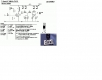 An RF power amplifier, providing 7 Watts output in HF bands, schematic by ON6MU
 -
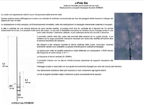 Homebrewed jpole antenna for 50 mhz by IW0BZD, include pictures and schematics, in italian.
 -
 RF Choke to prevent hf currents on the feedline or...1:1 Choke Balun, sometimes called the "UGLY BALUN"
 -
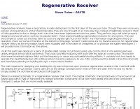 Project and schematic of a regenrative receiver by AA5TB
 -
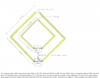
 A portable dualband dipole robust and compact antenna usable for horizontal and vertical polarisation by ON6MU
 -
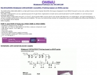 Wideband VHF/UHF/SHF monolithic PreAmp based on MARx-series by ON6MU
 -
 20/22 Ampere or 30/32 Ampere 13.8 volts power supply RE-PSF14A20 or PSF14A30 by ON6MU
 -
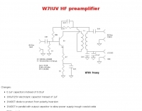 Schematic and pictures of a W7IUV preamplifier
 -
 1/2wave vertical antenna for the 6-meterband and a 5/8 ground plane antenna for 50 Mhz
 -
 G8ODE schema to reduce a half-size G5RV to 70 ft.
 -
 This Magnetic Longwire Balun (MLB) makes it possible to efficiently use a coaxial lead-in cable with all forms of longwires, T-forms or other types of wire antennas, without the need for an antenna tuner.
 -
 Schematics and purchasing information for the Yaesu FT - 8x7 DIY Bluetooth CAT micro miniature interface done by YO3GGX
 -
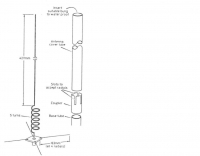
 Presents the design and construction of the OK2FJ Bigatas, a portable, automatically tuned vertical antenna covering 80 through 10 meters. It details two distinct control systems: one utilizing BCD band data from Yaesu FT-857/897 transceivers, and another employing voltage level sensing for the Yaesu FT-817. The resource provides specific instructions for building the antenna's radiating element, loading coil with switchable taps, and the control circuitry, emphasizing the use of readily available components. The article outlines the physical construction of the antenna, including the use of duralumin tubes for the radiator and a PVC tube for the coil form. It specifies coil winding details, tap points, and the integration of radial wires for ground plane operation. The control electronics section provides schematics and component lists for both the BCD decoder (using a 74LS42 IC) and the voltage comparator (using an _LM3914_ bargraph driver), enabling rapid, automatic band switching without the minute-long tuning delays common in other systems. Crucially, the antenna achieves rapid band changes, with typical SWR values centered on common operating segments, such as **3.7 MHz** for 80m SSB. It also discusses modifications for CW operation on 80m and the trade-offs between antenna efficiency and full-range automatic tuning on higher HF bands, where manual adjustment of radiator length is suggested for optimal performance on 15m, 12m, and 10m. The resource includes construction photos and a discussion of cable requirements for reliable operation.
 -
 These pages are entirely devoted to the Kenwood TS570 series Transceivers. Specifications & Brochure, Pictures, Schematics, Reviews, Manual and Modifications.
 -
 VHF Optimized Yagi Antenna for the 6-meter band (50 Mhz) by ON6MU
 -
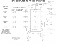 N6RK computer to FT-1000 interface
 -
 Schematic for Data CAT Power and Key cable interface for the Yaesu FT-450
 -
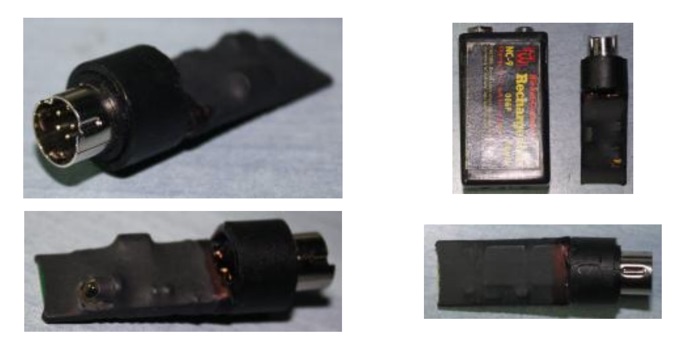
 The Kenwood TH-F6A handheld transceiver can achieve an extended transmit frequency range of 137-174 MHz, 216-235 MHz, and 410-470 MHz by removing a specific diode and chip resistor from the main PCB. This modification also expands the receive range on the A-band to 142-152 MHz, 216-235 MHz, and 420-450 MHz. For the TH-F7E, the transmit range extends to 137-174 MHz and 410-470 MHz, with a corresponding receive range on the A-band. Performing these hardware changes will reset and initialize the radio's memory contents, necessitating prior backup of important channel frequencies. Instructions are provided for constructing a homemade PC programming cable compatible with the Kenwood TH-G71A, TH-F6A, and TH-F7E. The interface utilizes an RS-232-to-logic (0-3.3V) level-shifter and a full-duplex serial connection, adapting the Kenwood PG-4S cable schematic for the TH-G71's 2.5mm and 3.5mm phono plugs. Specific schematic tweaks include changing R1 from 150 ohms to 1K ohm to optimize power from the serial port and adding a 150K ohm resistor between the Radio TXD and ground to manage the 3.3V I/O pin. Detailed plug pinouts for the 2.5mm and 3.5mm connectors are presented, with the interface's TXD connecting to the ring of the 2.5mm plug and RxD to the shield of the 3.5mm plug. Ground connects to the shield of the 2.5mm plug, while the tips of both plugs are no-connects. Debugging procedures cover verifying positive and negative power rails from the serial port, checking component polarities, and testing level-shifting and inversion functions of the interface. Software setup involves enabling "TC ON" (Menu 15 for TH-G71, Menu 9 for TH-F6) and using Kenwood's MCP programming software.
 -

-
 A schematic design of the W3DZZ antenna in portugues with description of trap building
 -
 This resource details the construction of a versatile CW/QRSS beacon, designed around a Microchip _PIC16F84_ microcontroller. The project provides a flexible platform for transmitting either standard CW or very slow QRSS signals, making it suitable for LF, VHF, UHF, and SHF applications. It supports two distinct messages, each configurable for speed (from 0 to **127** WPM for CW, or up to **127** seconds per dot for QRSS) and repetition within a six-phase sequence. The core functionality relies on the PIC's EEPROM, which stores all operational parameters, including message content, transmission speeds, phase configurations, and relay control settings. This design allows for parameter modification directly via programming software like _ICProg_ without altering the main program code. The project includes a detailed schematic, a component list, and an explanation of the EEPROM memory mapping for messages, speeds, phase settings, and inter-phase delays. General-purpose outputs (OUT1, OUT2, OUT3) provide dry relay contacts for external control, enabling functions such as power switching, antenna selection, or frequency changes. A 'TRIGGER' input facilitates controlled starts or continuous free-run operation. Sample EEPROM configurations illustrate how to program specific beacon sequences, including message content and relay states.
 -
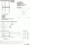
 Schematic Manual of the 3 element Yagi antenna by ECO antenne
 -
 Presents the detailed construction of the _FLA25HV_ antenna, a specialized array optimized for Earth-Moon-Earth (EME) communications on the 2-meter band. This resource provides schematics and practical insights into building a high-gain antenna system capable of reflecting signals off the lunar surface, a challenging but rewarding aspect of amateur radio. It covers the mechanical and electrical considerations essential for achieving the precise pointing and signal strength required for successful moonbounce contacts, often yielding **20 dB** or more gain. Amateur radio operators pursuing EME operations require robust antenna systems and precise tracking capabilities. The FLA25HV design addresses these needs by focusing on element spacing, impedance matching, and structural integrity to withstand environmental factors while maintaining critical alignment for lunar reflections. Such systems are crucial for making contacts over distances exceeding **768,000 km**. This personal page serves as a practical guide for hams interested in constructing their own EME arrays, offering a glimpse into the technical dedication involved in pushing the boundaries of VHF/UHF propagation.
 -
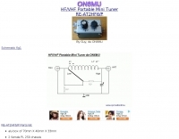 A small portable antenna tuner for HF and VHF bands by ON6MU
 -
 Demonstrates the construction of two distinct wideband RF preamplifiers, detailing their component requirements and performance characteristics. The first design leverages monolithic microwave integrated circuits (MMICs) such as the MAR-6, MAR-8, or PGA103, offering a broad frequency response from DC to 2 GHz with a gain of 22.5 dB at 100 MHz and a noise figure typically below 3 dB. This MMIC-based amplifier incorporates protection against power supply transients and features a 50 Ohm input/output impedance, operating from an 8-20 volt supply with low current drain. The second preamplifier design utilizes a BSX-20 transistor, providing amplification across the 14 MHz to 550 MHz range. This simpler, more economical build achieves an average gain of 12 dB at 145 MHz and a noise figure of approximately 1.1 dB. It operates from a 7-15 volt battery supply with a current draw of 6 mA. Both projects emphasize critical construction techniques, such as maintaining short RF connections, ensuring 50 Ohm impedance paths, and mounting the circuit within a shielded enclosure to optimize performance and minimize noise. The resource also discusses phantom power options for antenna-mounted preamplifiers and precautions for use with transceivers, including output protection diodes and static bleeders.
 -
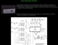 This page displays a 404 error, indicating the original content describing a simple _RS232 interface_ circuit is unavailable. The circuit was reportedly designed for older Kenwood transceivers and featured in chapter 22 of the _ARRL Handbook_. It likely involved basic electronic components for level shifting and signal conditioning between a computer's serial port and the radio's control interface. The intended project would have detailed the construction of a hardware interface, enabling CAT control for specific Kenwood models. Such interfaces typically convert TTL or CMOS logic levels from the radio to the +/-12V levels required by RS232, often utilizing ICs like the MAX232 or discrete transistor circuits. While the specific schematics and bill of materials are absent due to the page error, the context suggests a DIY electronics project for enhancing legacy amateur radio station functionality through computer control.
 -
 Specializes in antique radio schematics and capacitors. carries antique radio schematic diagrams and electronic circuit service information for american, canadian and european antique radios.
 -
 An RF power supply for 144 MHz schematics and instructions
 -
-
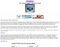
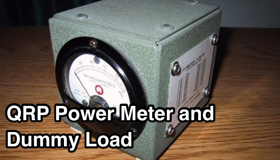 In this article the schematic is of AA5TB QRP power meter and dummy (50 Ohm) load combination
 -
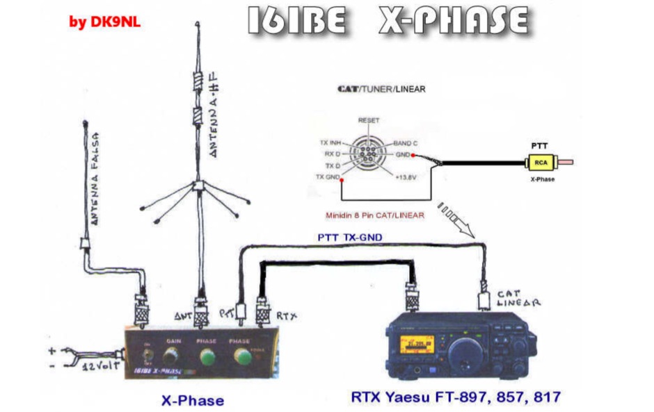 A project with several releases, of the Qkiller or QRM eliminator original project by DK9NL, in italian with schematics, picturs and movies
 -
 Schematic for Data, power, CAT, Key and Mic connection interface cable
 -
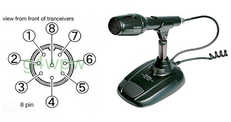 Yaesu MD-100 microphone schematic wire diagram with pin out
 -
 A pdf file with schematics of an ssb and cw filter AF amplifier
 -
 This is a compact three transistor regenerative general coverage receiver with fixed feedback
 -
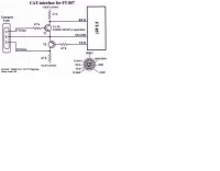 Schematic for Yaesu FT-857 CAT interface