Search results
Query: schematic
Links: 198 | Categories: 72
Categories
- Antique Radios > Schematics
- Antennas > Baluns > 1 to 1 Balun
- Antennas > 20M > 20 meter Vertical Antennas
- Antennas > Baluns > 4 to 1 balun
- Operating Modes > Amateur Television
- Technical Reference > Amplifiers
- Technical Reference > Antenna Rotator
- Technical Reference > Antenna Switch
- Technical Reference > APRS
- Technical Reference > Attenuators
- Technical Reference > ATV
- Technical Reference > Audio
- Technical Reference > Beacon keyers
- Radio Equipment > HF Vertical Antenna > Butternut HF2V
- Antennas > Capacitive
- Technical Reference > Components
- Technical Reference > Receivers > Crystal radio
- Technical Reference > Digital ATV projects
- Radio Equipment > Receivers > Drake R-4B
- Technical Reference > DTMF
- Technical Reference > Dummy Loads
- Technical Reference > Duplexers
- Antennas > EH
- Antennas > End-Fed > End Fed Half Wave Antenna
- Technical Reference > Frequency Counter
- Antennas > HB9CV
- Technical Reference > Headsets and Speakers
- Technical Reference > HF Radios
- Technical Reference > Homebrew
- Antennas > Horn
-
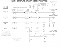 N6RK computer to FT-1000 interface
 -
 Schematic for Data CAT Power and Key cable interface for the Yaesu FT-450
 -
 The Kenwood TH-F6A handheld transceiver can achieve an extended transmit frequency range of 137-174 MHz, 216-235 MHz, and 410-470 MHz by removing a specific diode and chip resistor from the main PCB. This modification also expands the receive range on the A-band to 142-152 MHz, 216-235 MHz, and 420-450 MHz. For the TH-F7E, the transmit range extends to 137-174 MHz and 410-470 MHz, with a corresponding receive range on the A-band. Performing these hardware changes will reset and initialize the radio's memory contents, necessitating prior backup of important channel frequencies. Instructions are provided for constructing a homemade PC programming cable compatible with the Kenwood TH-G71A, TH-F6A, and TH-F7E. The interface utilizes an RS-232-to-logic (0-3.3V) level-shifter and a full-duplex serial connection, adapting the Kenwood PG-4S cable schematic for the TH-G71's 2.5mm and 3.5mm phono plugs. Specific schematic tweaks include changing R1 from 150 ohms to 1K ohm to optimize power from the serial port and adding a 150K ohm resistor between the Radio TXD and ground to manage the 3.3V I/O pin. Detailed plug pinouts for the 2.5mm and 3.5mm connectors are presented, with the interface's TXD connecting to the ring of the 2.5mm plug and RxD to the shield of the 3.5mm plug. Ground connects to the shield of the 2.5mm plug, while the tips of both plugs are no-connects. Debugging procedures cover verifying positive and negative power rails from the serial port, checking component polarities, and testing level-shifting and inversion functions of the interface. Software setup involves enabling "TC ON" (Menu 15 for TH-G71, Menu 9 for TH-F6) and using Kenwood's MCP programming software.
 -
 A schematic design of the W3DZZ antenna in portugues with description of trap building
 -
 This resource details the construction of a versatile CW/QRSS beacon, designed around a Microchip _PIC16F84_ microcontroller. The project provides a flexible platform for transmitting either standard CW or very slow QRSS signals, making it suitable for LF, VHF, UHF, and SHF applications. It supports two distinct messages, each configurable for speed (from 0 to **127** WPM for CW, or up to **127** seconds per dot for QRSS) and repetition within a six-phase sequence. The core functionality relies on the PIC's EEPROM, which stores all operational parameters, including message content, transmission speeds, phase configurations, and relay control settings. This design allows for parameter modification directly via programming software like _ICProg_ without altering the main program code. The project includes a detailed schematic, a component list, and an explanation of the EEPROM memory mapping for messages, speeds, phase settings, and inter-phase delays. General-purpose outputs (OUT1, OUT2, OUT3) provide dry relay contacts for external control, enabling functions such as power switching, antenna selection, or frequency changes. A 'TRIGGER' input facilitates controlled starts or continuous free-run operation. Sample EEPROM configurations illustrate how to program specific beacon sequences, including message content and relay states.
 -
 Schematic Manual of the 3 element Yagi antenna by ECO antenne
 -
 Presents the detailed construction of the _FLA25HV_ antenna, a specialized array optimized for Earth-Moon-Earth (EME) communications on the 2-meter band. This resource provides schematics and practical insights into building a high-gain antenna system capable of reflecting signals off the lunar surface, a challenging but rewarding aspect of amateur radio. It covers the mechanical and electrical considerations essential for achieving the precise pointing and signal strength required for successful moonbounce contacts, often yielding **20 dB** or more gain. Amateur radio operators pursuing EME operations require robust antenna systems and precise tracking capabilities. The FLA25HV design addresses these needs by focusing on element spacing, impedance matching, and structural integrity to withstand environmental factors while maintaining critical alignment for lunar reflections. Such systems are crucial for making contacts over distances exceeding **768,000 km**. This personal page serves as a practical guide for hams interested in constructing their own EME arrays, offering a glimpse into the technical dedication involved in pushing the boundaries of VHF/UHF propagation.
 -
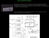 This page displays a 404 error, indicating the original content describing a simple _RS232 interface_ circuit is unavailable. The circuit was reportedly designed for older Kenwood transceivers and featured in chapter 22 of the _ARRL Handbook_. It likely involved basic electronic components for level shifting and signal conditioning between a computer's serial port and the radio's control interface. The intended project would have detailed the construction of a hardware interface, enabling CAT control for specific Kenwood models. Such interfaces typically convert TTL or CMOS logic levels from the radio to the +/-12V levels required by RS232, often utilizing ICs like the MAX232 or discrete transistor circuits. While the specific schematics and bill of materials are absent due to the page error, the context suggests a DIY electronics project for enhancing legacy amateur radio station functionality through computer control.
 -
 Specializes in antique radio schematics and capacitors. carries antique radio schematic diagrams and electronic circuit service information for american, canadian and european antique radios.
 -
 An RF power supply for 144 MHz schematics and instructions
 -
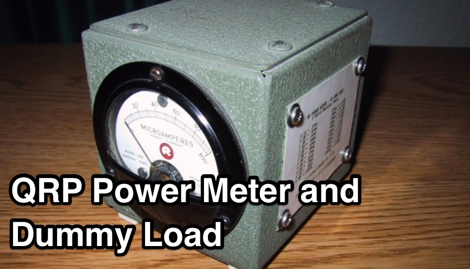 In this article the schematic is of AA5TB QRP power meter and dummy (50 Ohm) load combination
 -
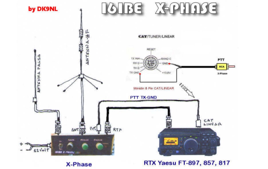 A project with several releases, of the Qkiller or QRM eliminator original project by DK9NL, in italian with schematics, picturs and movies
 -
 Schematic for Data, power, CAT, Key and Mic connection interface cable
 -
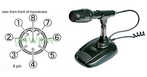 Yaesu MD-100 microphone schematic wire diagram with pin out
 -
 A pdf file with schematics of an ssb and cw filter AF amplifier
 -
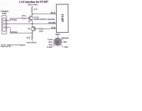 Schematic for Yaesu FT-857 CAT interface
 -

-
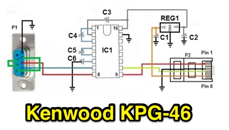 Schematic diagram for the Kenwood KPG 46 programming cable interface for Kenwood TM 271E TK 71 TK 81 TK 7302 NX 700 NX 800 series
 -
 This resource, "Transistor Audio Preamplifier Circuits," offers comprehensive design guidelines for constructing **bipolar transistor** audio preamplifiers. It delves into critical aspects such as quiescent current setting, voltage gain calculation, and the impact of various component choices on circuit performance. The content provides several _schematic diagrams_ illustrating different preamplifier configurations, including single-stage common emitter and two-stage designs, alongside explanations of their operational characteristics and practical implementation considerations. The analysis extends to frequency response, noise performance, and distortion, providing insights into optimizing these parameters for specific audio applications. The resource presents calculated gain figures for various stages, demonstrating how to achieve desired amplification levels. It also discusses the importance of proper power supply decoupling and input/output impedance matching, crucial for integrating these preamplifiers into larger audio systems or ham radio transceivers. The practical application of these designs is evident in their suitability for microphone preamplifiers or general-purpose audio amplification.
 -
-
 WV7U's YC156 and 3CPX800 amplifier projects. Everything you wanted to know about using the YC156 or 3CPX800 in a ham radio linear amplifier. See pictures, schematics, test data, links, and more!
 -
 A schematic antenna for a 40-80 Morgain dipole antenna with diagram and pictures, article partially in german
 -
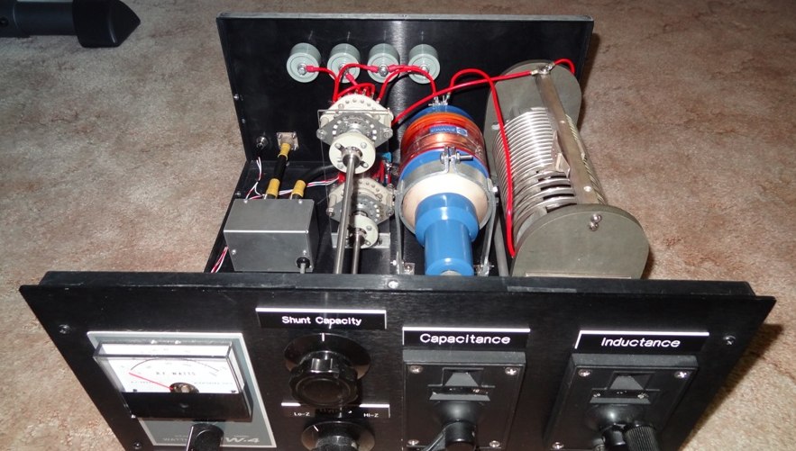 An interesting home made project of an L Network Antenna Tuner Project with pictures and schematics by K7SFN
 -
 A microphone preamplifier schematic for hand-helds by ON6MU
 -
 Antique Radio Schematics and Service Manuals for Tube Radios
 -
-
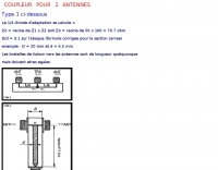
 About different baluns types. Samples and schematics for several ratios baluns in french
 -
-
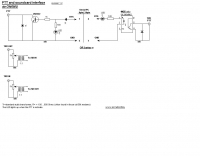 PTT and soundcard interface schematic by ON6MU
 -
 Make your own interface, two schematics for building an interface using the RTS line by N3UR
 -
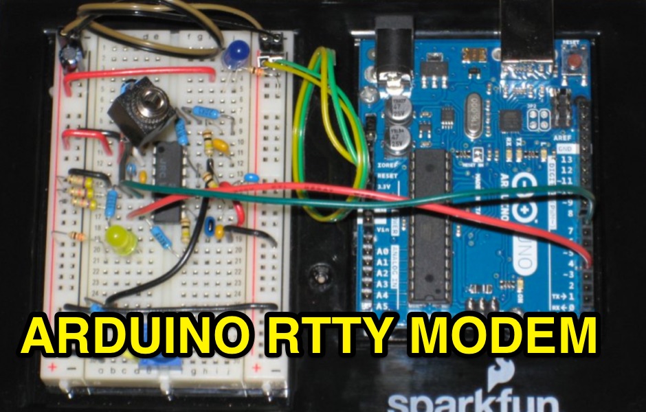 A project for a simple RTTY decoder based on Arduino UNO R3. Includes the RTTY modem source code available for download along to schematics pictures and references.
 -
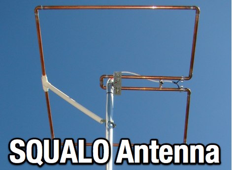 A SQ Loop antenna for 50 MHz, project include pictures and schematic diagram
 -
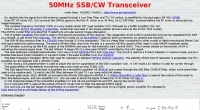 A SSB CW transceiver for six meters band with schematic and block diagram
 -
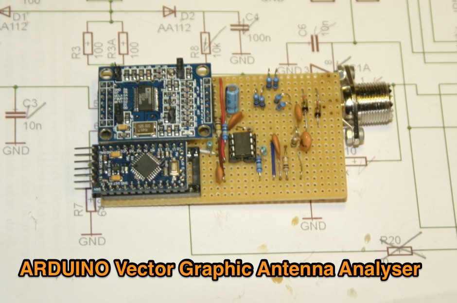 A vector graphic antenna analyzer project page by DC2WK demonstrating a project realized by DG7EAO includes, part list, schematics, and videos.
 -
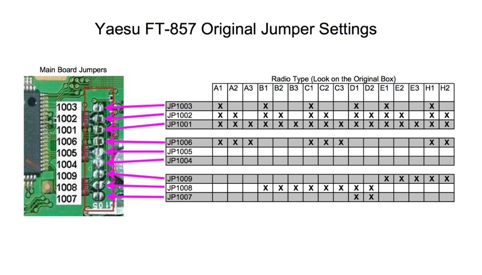 Schematic of Yaesu FT-857 main board original jumpers based on different radio type
 -
 Schematic anc PCB for a fox hunting receiver for 80 meters band
 -
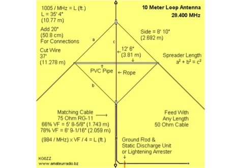 A nice loop antenna project for 28 MHz with schematic diagram, construction details and a complete video instruction
 -
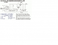
 A 4 AMP / 18V regulated power supply schematic, designed by _ON6MU_, provides a detailed circuit diagram for constructing a robust power source. The design focuses on delivering a stable 18-volt output at up to 4 amperes, crucial for powering various amateur radio equipment. This resource presents a clear visual representation of component interconnections, including rectifiers, filter capacitors, and voltage regulation stages, essential for DIY enthusiasts building their shack infrastructure. The schematic's clarity facilitates understanding the power flow and component roles within the circuit. This circuit design offers a practical solution for hams needing a reliable 18V supply, potentially useful for driving specific transceivers, amplifiers, or accessory circuits. While specific performance measurements or comparisons to other designs are not detailed, the schematic itself serves as a foundational blueprint. Builders can adapt or modify the _power supply_ to suit their particular needs, such as integrating overcurrent protection or fine-tuning the output voltage with adjustable regulators. The straightforward presentation makes it accessible for those with basic electronics knowledge to assemble and troubleshoot.
 -
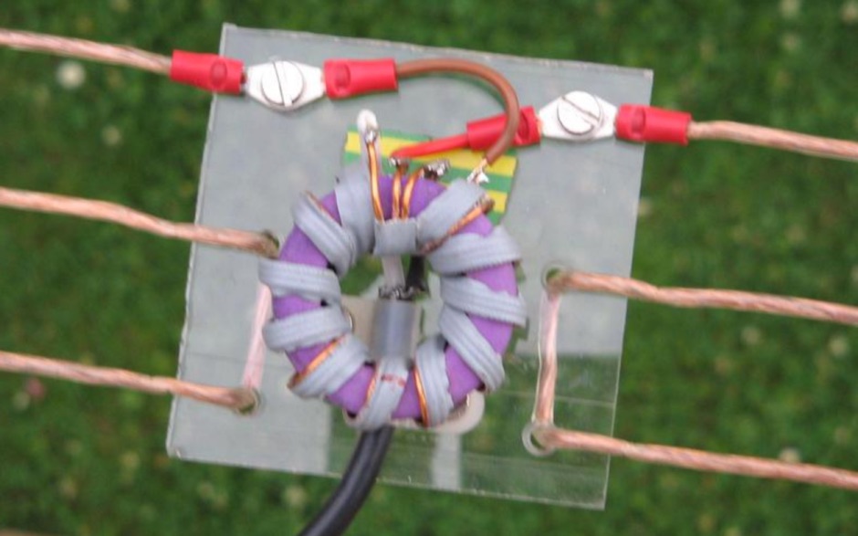
 One point eight MHz to 30 MHz is the operational bandwidth for this 4:1 Ruthroff voltage balun, designed to interface an unbalanced T-Match network with a balanced antenna system. The project details the construction using a _T200-2_ powdered iron toroid core, tightly wrapped in PVC electrical tape for insulation, and wound with 17 double bifilar turns of 1.25mm enamelled copper wire. This outboard balun offers flexibility, allowing hams to trial various baluns based on antenna system and impedance characteristics, rather than integrating it directly into the tuner. The resource includes a schematic of the balun, a wiring diagram showing winding connections, and a table suggesting alternative toroid cores like the T80-2 or T400-2 with corresponding winding counts. Component sourcing is straightforward, listing items such as the _Amidon_ T-200-2 core, SO-239 connector, and a sealed polycarbonate enclosure from Jaycar. Performance evaluation was conducted using an _AIM 4170C_ antenna analyser, demonstrating efficient 1:4 voltage transformation across the specified HF spectrum. Further efficiency tests involved measuring RF power loss at various frequencies, revealing minimal loss—less than 0.7 dB from 3.6 MHz to 30 MHz, and only 2.0 dB at 1.8 MHz. These measurements, performed under ideal 50-ohm conditions, confirm the balun's effectiveness as a low-loss interface for multi-band antenna systems. The page also links to several other balun and unun projects, including 1:1 current and voltage baluns, and 9:1 voltage ununs, providing a broader context for impedance matching solutions.
 -
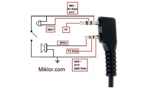 Speaker Microphone Pin Out, Dual PTT Switching,Programming Cables, SMA Antenna Connection, Extended Antenna Threads for Baofeng UV 3, UV 5 Series handheld transceivers
 -
 The resource presents a detailed schematic for constructing a dual-band vertical antenna, specifically designed for operation on the 2-meter and 70-centimeter amateur radio bands. It illustrates the physical layout, critical dimensions, and component placement necessary for successful replication. Key elements such as the radiating elements, phasing sections, and feed point are clearly depicted, providing a visual guide for radio amateurs undertaking a homebrew antenna project. The diagram specifies the lengths for the VHF and UHF sections, indicating how these elements are integrated to achieve dual-band functionality from a single coaxial feedline. It also implies the use of common materials readily available to most experimenters, focusing on simplicity and effectiveness in its design. The visual format of a GIF image ensures direct access to the construction details without requiring extensive textual interpretation. This schematic serves as a practical reference for hams interested in building a compact, efficient vertical antenna for local and regional FM communications, offering a proven design for immediate implementation.
 -

-
 Presents a QRP AM/CW transmitter project specifically designed for the 10-meter band, utilizing a crystal oscillator and a collector-modulated AM oscillator. The design employs a 2N2219(A) transistor in a Colpitts configuration, generating 100 to 350 mW of RF output power depending on the 9-18 Volt supply voltage and modulation depth. Frequency stability is maintained by a 28 MHz crystal, with fine-tuning possible via a Ct1 trimmer capacitor for approximately 1 kHz adjustment. The resource details the RF oscillator stage, implemented with a 2N2219 NPN transistor, emphasizing frequency stability and low power dissipation. It also covers the amplitude modulation stage, managed by a 2N2905 PNP transistor, which impresses audio information onto the carrier. Selective components (C3, C4, C7, C5) enhance voice frequencies within a +/- 5 kHz bandwidth, and modulation depth is controlled by R2 and R3. The project includes a 3-element L-type narrow bandpass filter (Ct3, L3, C10) to suppress harmonics and ensure a clean output signal. The project provides a complete schematic diagram, a comprehensive parts list including specific capacitor, resistor, and inductor values, and construction notes for the coils (L1, L2, L3). It also offers practical advice on enclosure requirements, suggesting an all-metal case or a PVC box with graphite paint for RF shielding. Operational parameters such as current draw (27mA@9V to 45mA@16V) and input impedance (50 Ohms) are specified, alongside guidance on antenna matching and the importance of a valid amateur radio license for 10-meter band operation.
 -
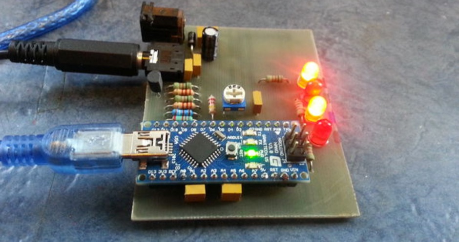 An Arduino TNC modem project based on KI4MCW source code with pictures and schematics
 -
 Hammarlund HQ-129X Receiver, Heathkit C-3 Condenser Checker, Heathkit QF-1 Q-multiplier and more
 -
 This is a "techie" site, dedicated to presenting service manuals, parts lists, schematic diagrams and other information of value to restorers and technicians who try to keep these radios working
 -
 Operating on the 2200m band (135.7-137.8 kHz) often presents challenges for amateur radio transceivers, which typically exhibit poor receiver performance at these very low frequencies. This project addresses the issue by providing a design for a dedicated 137 kHz antenna preamplifier, specifically tailored to improve signal reception for radios such as the _Yaesu FT-817_. The preamplifier circuit utilizes a low-noise FET input stage, crucial for minimizing self-generated noise and maximizing the signal-to-noise ratio from weak LF signals. The design includes a detailed schematic, component values, and construction notes, enabling homebrewers to build a functional unit. The goal is to achieve significant gain, making the faint signals on 2200m more discernible and improving overall band usability. Key design considerations include impedance matching to typical antenna systems and ensuring stable operation across the narrow LF segment. The circuit aims for a **low noise figure** and sufficient amplification to overcome the inherent limitations of general-purpose HF transceivers when operating below **200 kHz**.
 -
 Color photos, schematic and diagrams for an article written by N2APB for Fall 2000 QRPp. Also the subject of a presentation made at the Pacificon QRP Forum in October 2000.An Integrated and Portable PSK Station for 80 & 20 without using a PC!
 -
 For radio amateurs and electronics enthusiasts maintaining vintage tube gear, having accurate documentation for tube testers is crucial. Michael Marx, WB0SND, through SND Tube Sales, provides high-quality reproductions of these essential manuals. These aren't mere photocopies; each manual is digitally scanned, cleaned of imperfections, and professionally printed on a _Laserjet 5000_ with heavy card stock covers and plastic comb binding, often making them difficult to distinguish from originals. The catalog includes instruction manuals, schematics, and roll chart supplements for a wide array of classic tube testers. Operators can find documentation for popular models such as the _Hickok 539B/C_, _AVO CT-160_, and _B&K 700_, along with military-grade testers like the _TV-7_ and _USM-118_. Many listings also offer specialized supplements for obsolete or foreign tubes, ensuring comprehensive coverage for diverse tube collections. WB0SND's offerings extend to calibration instructions and data for specific adapters like the _Hickok CA-4_ and _CA-5_, providing critical support for precise tube testing.
 -
 This is the schematic of asolid-state 7 MHz QRP CW transmitter by VU2NAN