Search results
Query: tech
Links: 452 | Categories: 115
This query is too generic. Please try adding an additional term to focus your research.
Categories
- Ham Radio > Clubs > Technical Specialty
- Antennas > Homebrewing Techniques
- Technical Reference
- Antennas > 6M > 6 meter Yagi Antennas
- Operating Modes > 70 MHz
- Antennas > 70cm
- Radio Equipment > HF Amplifiers > Acom 1010
- Technical Reference > AI Ham Radio
- Ham Radio > Clubs > North America > USA > Alabama
- Radio Equipment > HF Amplifiers > Alpha 8410
- Radio Equipment > HF Amplifiers > Alpha 9500
- Operating Modes > AM
- Radio Equipment > HF Amplifiers > Ameritron AL-80B
- Operating Modes > Satellites > Analog Satellites
- Technical Reference > Arduino
- Radio Equipment > Antenna Analyzers > Array Solutions AIM 4170D
- Ham Radio > Blogs > Asia
- Radio Equipment > VHF-UHF Handhelds > Baofeng UV-3R
- Technical Reference > Software Defined Radio > Beginner's Guides to SDR
- Technical Reference > Radio Frequency Interference > BPL
- Operating Modes > Chip64
- Technical Reference > Coax Cables and Connectors
- Ham Radio > Clubs > North America > USA > Colorado
- Technical Reference > Components > Component Database
- Technical Reference > Components
- Radio Equipment > HF Vertical Antenna > Cushcraft R7
- Radio Equipment > HF YAGI Antennas > Cushcraft X7
- Operating Modes > D-STAR
- Technical Reference > Components > Datasheets
- Operating Modes > Digital ATV
-
-
-
 Offer PC based virtual instrument for electronics enthusiasts, students and professionals, including full-fledged sound card real time Oscilloscope, Spectrum Analyzer and Signal Generator.
 -

-
-
 HF amplifiers manufacturer maker of HF-2000 RF power amplifier
 -
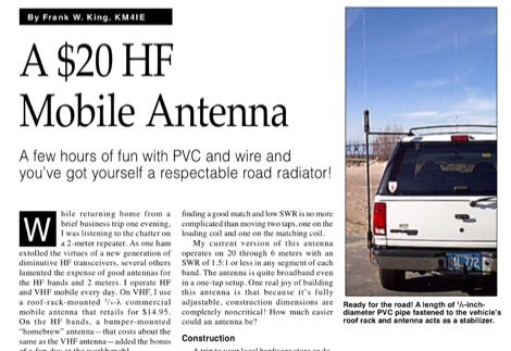 A few hours of fun with PVC and wire and you have got yourself a respectable road radiator. The antenna consists of little more than some PVC pipe topped by a RadioShack replacement whip antenna and a couple of coils made from a small roll of #14 house wire.
 -
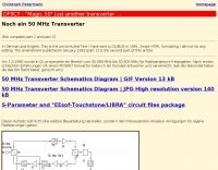 Complete 144/50 MHz transverter with GaAs Fet LNA and 400 mW out. No printed circuit board. Schematics and images by Christoph Petermann DF9CY
 -
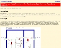 432 MHz EME low noise amplifier. Circuit, components and image by Christoph Petermann DF9CY
 -
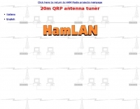
 Presents a catalog of **QRP** transceivers, antenna tuners, and related accessories for amateur radio operators. The product line includes the ZM-2 antenna tuner, designed for efficient impedance matching across HF bands, and the NW-series QRP transceivers, offering low-power CW operation. Additionally, the site details various ladder line insulators and specialized connectors, emphasizing robust construction for field deployment and home station use. Each product listing provides specifications, operational parameters, and pricing information. Compares the features of different **QRP transceiver** models, such as the NW-40 and NW-20, highlighting their respective band coverage and power output capabilities. The ZM-2 tuner's performance is detailed with typical SWR reduction figures for various antenna types, demonstrating its utility for portable and fixed stations. Customer testimonials and product images illustrate the practical application and build quality of EMTECH's offerings, providing insights into their durability and ease of integration into existing amateur radio setups.
 -
 This PDF document provided by AT technologies explains how to build the K9AY loop receiving antenna.
 -
 A bazooka antenna project for the 7 Mhz, includes dimension for to homebrew your own bazooka for HF bands
 -
 The latest and best yagi beams for 432MHz tested and optimized with NEC
 -
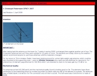
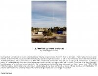 The J pole vertical for 14MHz is built from a fifty-foot TV push up mast by Mike Higgins, K6AER
 -
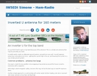
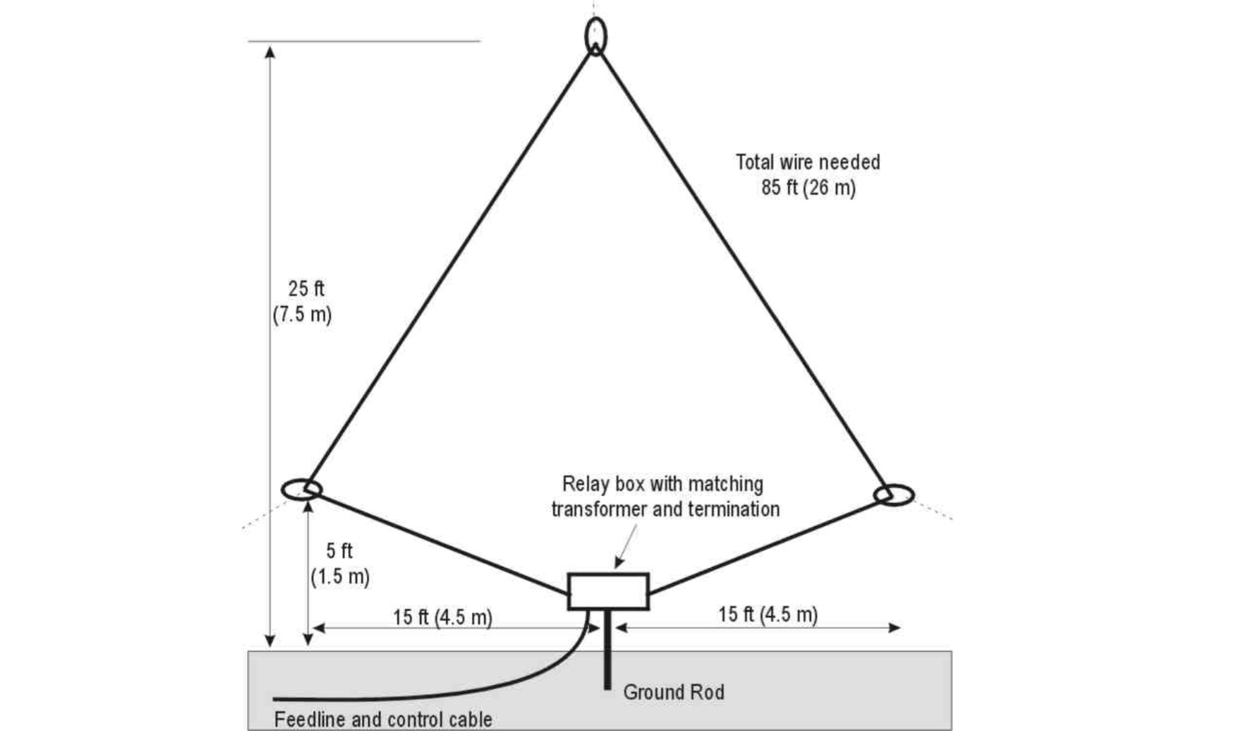
 This type of antenna has same performance as a dipole, but requires only one single mounting point
 -
 Explanation of antenna basics concepts like antenna gain at marc's technical pages
 -
 Some thoughts on a "hardware-store special" 2-meter quad, and a modified quad for 2 or 10 meters by K3MT
 -
 A modern version of the classic regenrative receiver designed and built by Charles Kitchin ARRL Article
 -
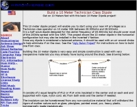 Build a 10 Meter Technician Class Dipole antenna. Get on 10 Meters fast with this basic 10 Meter Dipole project by hamuniverse
 -
 A very interesting and informative introduction to the 50 MHz band, also known as 6 meters or better the Magic Band, by Dave Finley N1IRZ, covering different propagation modes, operating experiences, and the excitement of the band. The content provides insight into the unique characteristics of six meters and its unpredictability in signal propagation.
 -
 A 10-meter J-Pole antenna, detailed in QST February 1950, offers a straightforward solution for hams operating with restricted space. This design, originally presented by W1BLR, is a **half-wave radiator** fed by a quarter-wave matching stub, providing a low-angle radiation pattern beneficial for DX. The article describes building the antenna from readily available materials like copper pipe, emphasizing its simplicity and effectiveness for **single-band operation**. The J-Pole's inherent design provides a good impedance match to 50-ohm coaxial cable without the need for an external tuner, a significant advantage for portable or minimalist stations. Its nondirectional pattern ensures coverage in all directions, making it a versatile choice for general operating on the 28 MHz band. The construction plans are clear, allowing even those with basic workshop skills to assemble a functional antenna.
 -
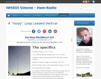 A loopy loop loaded vertical antenna operating range 7.0 to 7.3 MHz by S. C. Chuck Smith, WA7RAI
 -
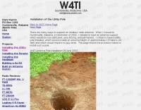 There are many ways to support an amateur radio antenna. Installatio of a utility pole will provide an antenna height of approximately 13 meters (40 feet) and will require no guy wires.
 -
 The document is a PDF detailing the construction of the DBJ-1 VHF-UHF Dual Band J-Pole antenna for amateur radio use. It provides instructions on how to build a high-performance dual band base antenna for VHF and UHF bands using a single feed line for less than $10.
 -
 AEA Technology Inc. is a pioneer and leading manufacturer of RF and cable test equipment for the wireless, Telco, CATV, NMR & MRI, RFID, telemetry, aviation, commercial, military, and two-way radio industries. Produces SWR Meters, Pre Amplifiers, filters, power meters and antenna testing products
 -

-
 A 20 meter quarter wave vertical antenna by jerry sevick W2FMI QST Article
 -
 This page explains how to construct high-Q inductor coils.
 -
 Building guide for a two element quad antenna planned for 28 and 21 Megahertz
 -
 Service Manuals & Schematics, supplied for most types of equipment, Audio, TV, Video, Test and Ham Radio
 -
-

-
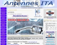 French manufacturer (F5MSU) of antennas and accessories since 1999 : Yagi, Delta-loop, dipoles, T2FD, verticales, EFHW, baluns, ununs, etc.
 -
 Technical reference about Accessories, Amplifiers, Antennas, Cable and Connectors, Filters, Geography, Grounding, Gunk, Matching Networks, Projects, Propagation Info Radios, RFI/EMI, Rotors, Station Setup, Towers.
 -
 Constructing a **2-meter** J-pole antenna from readily available copper plumbing components offers a robust and cost-effective solution for VHF operation. This design, dubbed the "Plumber's Delight," functions essentially as a half-wave dipole fed by 50-ohm coax via a **gamma match**. It incorporates a quarter-wave copper tubing support, which, when affixed to a metal mast or tower, enhances forward power in the direction of the radiating elements. The original configuration utilized a small ceramic trimmer capacitor for the gamma match, suitable for up to 10 watts. A subsequent modification replaced this with a 50 pF variable capacitor housed in a plastic enclosure, accommodating higher RF power and improving weather resistance. The antenna elements are secured using a copper "T" fitting, and an SO-239 connector mounts directly to this fitting. Performance includes gain away from the support mast, and tuning is straightforward by adjusting the gamma match capacitor for a 1:1 SWR. The total cost for materials, excluding the capacitor and coax, can be under $10.
 -
 A 2-meter Turnstile antenna, detailed for amateur satellite communication, offers a straightforward build for those looking to engage with orbiting transponders. The author, WB8ERJ, shares his personal design and construction methods, emphasizing the antenna's simplicity and effectiveness for LEO (Low Earth Orbit) satellite work. This design provides a circularly polarized signal, crucial for mitigating _Faraday rotation_ and signal fading often encountered with linearly polarized antennas when tracking satellites. Construction involves readily available materials like PVC pipe and copper wire, making it an accessible project for many hams. The article includes practical advice on element spacing and feed point considerations, drawing from the author's hands-on experience in the shack and field. It highlights the antenna's utility for receiving signals from various amateur satellites, including the popular AO-91 and AO-92. The Turnstile's inherent omnidirectional pattern in the horizontal plane, combined with its circular polarization, yields consistent signal reception, often resulting in **stronger decodes** and **more reliable contacts** compared to basic dipoles or verticals.
 -
 The BV6 50 MHz Yagis resource details the construction of two distinct Yagi antenna designs for the 6-meter band, specifically a 1-wavelength (1wl) model and a 2.1-wavelength (2.1wl) model. The 1wl Yagi, with a boom length of 5.850m, achieves a gain of **9.4 dBd**, while the 2.1wl Yagi, spanning 12.90m, boasts a gain of **11.9 dBd**. These designs adhere to a proven methodology for optimizing current slope and maintaining constant phase delay across parasitic elements, ensuring high gain per boom length and an _excellent pattern_. Both designs target a 50-ohm input impedance, facilitating straightforward feeding with a robust folded dipole. Final verification using NEC-II software confirmed the antennas' exceptional stacking capabilities, yielding stacking gains exceeding **5.8 dB** for a 2x2 array with minimal mutual detuning. The resource provides common mechanical data, including boom and element diameters, and specifies element lengths corrected for boom diameter. While the original _DUBUS Technik V_ publication contained incorrect element lengths, this resource provides the accurate dimensions for proper construction, emphasizing the use of readily available materials for cost-effective amateur radio deployment.
 -
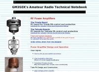
 Source of common model manuals and amateur help on amplifier problems for the amateur bands, Discussion of vacuum tube amplifiers. Technical information and discussion of obselete tube replacement.
 -
 Simple gain antennas for the beginner, a 2 element HF yagi antenna
 -
 Information regarding CB radio and the problems you may encounter during installation and use of your system.
 -
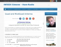
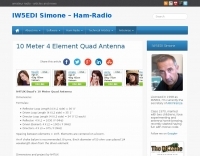 Dimension and formula for a 4 element QUAD antenna for the 10 meters band
 -
 A lot of good informations concerning antennas, filters, moonbounce, and circuitry data.
 -

-
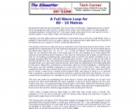 VE3HCR article of a home made loop antenna for 80 meters band
 -
 Do your multiple-transmitter field day or contest efforts suffer from intrastation interference ?
 -
 Demonstrates the construction of a **homebrew spectrum analyzer** designed by Wes Hayward, W7ZOI, and Terry White, K7TAU, enabling radio amateurs to build a capable test instrument without significant expense. The resource details a _double-conversion superheterodyne_ circuit, employing intermediate frequencies of 110 MHz and 10 MHz, and covers essential blocks such as the time base, logarithmic amplifier, resolution filters, and local oscillators. It highlights the use of hybrid and monolithic ICs, including mixers, amplifiers, and VCOs, to simplify construction while maintaining performance. The design supports useful measurements in the 50 kHz to 70 MHz range, with methods outlined for extending capabilities into VHF and UHF. The authors emphasize that this analyzer, while simple to build, is intended for serious measurements, requiring careful control of signal levels to avoid spurious responses. It uses an oscilloscope for display, with specific instructions for calibration and adjustment of various stages, including the log amplifier and IF gain. The guide provides detailed schematics and component lists for each section, such as the 110 MHz triple-tuned band-pass filter, which achieved **90 dB** image rejection, a significant improvement over double-tuned circuits. Practical advice on alignment and troubleshooting is included, drawing on the authors' extensive experience in RF circuit design.
 -
 RFI/EMI RadioFrequency interference/electromagnetic interference by ARRL Technical Information Service page
 -
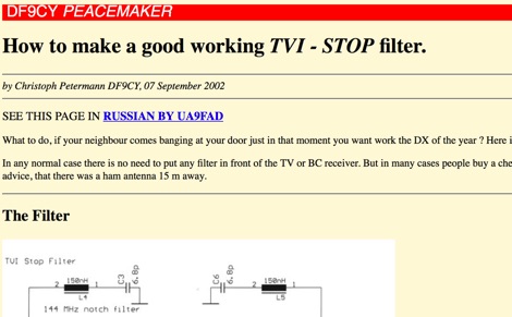 TVI and BCI bandpass and bandstop filters in SMD technique. Schematics and images.
 -
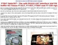 The safe RS232 CAT interface and PA buffer for Yaesu FT-817, FT-857, FT897 and FT-100 rigs
 -
 Well documented Amateur Radio HF/VHF antenna projects, high power Russian GS35B RF amplifiers, mobile RFI solutions, related accessories, vintage radios, Six meter equipment, and useful techniques by K8CU are inside.