Search results
Query: vertical antenna constru
Links: 85 | Categories: 7
-
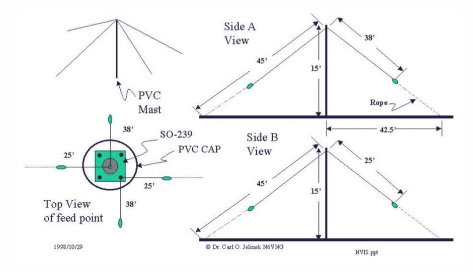 Introduction to NVIS antenna and NVIS propagation. A simple NVIS antenna can be constructed as shown in this article
 -
 This DIY vertical multi-band Windom antenna offers a practical and effective solution for amateur radio enthusiasts seeking a versatile and compact antenna for HF communications. Its simplicity of construction, multi-band capability, and favorable performance make it a valuable addition to any radio shack. The article provides detailed instructions on constructing the antenna and balun, along with diagrams and component specifications. Field tests demonstrated successful contacts with stations across Europe and North America on 14, 18, and 28 MHz. The antenna exhibited comparable performance to a W3DZZ dipole and outperformed a Cobweb antenna on 18 MHz. Low noise levels were observed, effectively suppressing background noise.
 -
 The Tri-pole antenna, a clever modification of a standard dipole, allows for dual-band operation by integrating a third element. This design effectively shortens the overall dipole length by 10 to 20 percent, simplifying antenna rotation and offering a compact footprint. KK4OBI's article delves into the operational principles, using a 6 and 10-meter Tri-pole as a primary example, and provides comprehensive instructions for constructing any Tri-pole antenna within the 6 to 15-meter range. Key to the Tri-pole's performance is its off-center feed, necessitating a common mode choke at the feed point for optimal tuning and reduced noise. The author outlines a methodical approach to determining element dimensions, starting with a vertical element frequency calculated as 0.47 times the sum of the desired upper and lower band frequencies. This calculation, along with K-values derived from trend lines, guides the initial lengths for the horizontal arms, demonstrating how a 10m-6m Tri-pole can achieve a total horizontal length 78% shorter than a conventional 10-meter dipole. Tuning and balancing are critical, with the article detailing adjustments to arm lengths and the vertical element to achieve balanced SWR values, as validated through 4NEC2 simulations. Radiation patterns are analyzed at various elevations, showing gains around 5.7 dBi and favorable take-off angles for DX contacts. Construction details specify aluminum tubing dimensions, U-bolts, and an SO-239 connector, emphasizing the importance of a ferrite-based choke for wideband operation.
 -
 This article presents a comprehensive guide to constructing a multiband vertical wire antenna. The design features parallel wires for various bands, all connected to a single balun, ensuring ease of assembly and adjustment. Materials required include a fishing rod, PVC tubing, and inexpensive wire. The antenna is lightweight, cost-effective, and suitable for field use or as an additional home setup. Detailed instructions and diagrams are provided to facilitate successful construction and optimal performance across multiple frequencies.
 -
 The PAC-12 Antenna, a multi-band portable vertical, is meticulously detailed in this construction article by James Bennett, _KA5DVS_. The design emphasizes ease of homebrewing using readily available components from local hardware stores, including replaceable loading coils. It outlines the preparation of the 72-inch telescoping whip (originally from Radio Shack, with an alternate source now provided by _Pacific Antenna_), the construction of the loading coils from PVC risers, and the fabrication of the aluminum rod base sections. Specific instructions cover threading aluminum rod with a _1/4-20 threading die_ and assembling the feedpoint insulator with a BNC connector, along with recommendations for radial deployment. KA5DVS, an avid traveler and QRP enthusiast, developed the PAC-12 to address the bulkiness of random wire setups and the limitations of commercial portable antennas like the Outbacker or SuperAntennas MP1. His goal was a lightweight, packable antenna that disassembles into 12-inch sections, achieving an assembled length of approximately 8 feet. The design strategically places the loading coil away from the base for improved efficiency. The PAC-12 notably placed first in efficiency compared to a quarter-wavelength wire vertical at the HFPack antenna shootout during the Pacificon conference in October 2001, demonstrating its practical performance for field operations. Appendix C showcases various _NJQRP Club_ members' PAC-12 constructions, including a 20m beam made with multiple PAC-12 elements.
 -
 Building an 80-160 meter antenna in a small garden (9m x 14m) involves creative solutions due to space constraints. This project outlines the construction of a trapped 80-160 meter vertical dipole, utilizing a crank-up tower and an 11-meter fiberglass pole. The design prioritizes minimal visibility, ease of construction, and cost-effectiveness, achieving effective operation despite limited space.
 -
 This article shares the author's experience with building antennas. After putting a large magnetic loop project on hold, they decided to try a base-loaded vertical antenna. The author explains how they chose to design a new antenna from scratch, aiming for a frequency of 7 MHz. They describe the calculations needed to find the right coil inductance and how they used 3D-printed parts for the construction. The article wraps up with results from their initial tests, showing good communication on different bands and highlighting the success of their design.
 -
 This article explores the evolution of antenna choices for DXpeditions, focusing on the shift from mono-band VDAs to a multi-band solution. It details the design and construction of a lightweight, versatile 20-17-15m VDA, utilizing readily available materials like fishing rods and IKEA breadboards. The author discusses challenges, adjustments, and offers guidance for replication.
 -
 Constructed in May 2008, this innovative 4m tall electrically full-size halfwave vertical dipole, tunable to multiple bands, offers HF coverage despite its space-saving design. Inspired by cost-effective DIY alternatives, the antenna design departs from conventional center-fed approaches, utilizing asymmetrical dimensions. Despite resonance challenges, the antenna's performance remains viable, boasting broad bandwidth and adaptability, as demonstrated through SWR measurements and EZNEC predictions.
 -
 A coaxial cable trap is a fundamental component in multiband antenna design, enabling a single radiator to resonate efficiently on multiple frequencies by electrically shortening or lengthening the antenna element. This project focuses on constructing such a trap for a vertical antenna operating on the 10 MHz (30m) and 14 MHz (20m) amateur bands, providing practical insights into its fabrication and integration. The article outlines the specific dimensions and winding techniques for the coaxial trap, emphasizing the use of readily available materials. It details the physical construction of the vertical element, including the mast and radiating sections, to achieve optimal performance across both target bands. The author shares personal experiences with similar trap designs, noting their effectiveness in previous horizontal dipole configurations. Key construction steps are illustrated with _original photos_, showing the assembly of the trap and its incorporation into the overall antenna structure. The design aims for a compact footprint, making it suitable for limited space installations while still delivering effective DX capabilities on the **30-meter** and **20-meter** bands.
 -
 Learn how to easily build a 10-meter vertical antenna, perfect for DX contacts on the amateur radio bands. This flowerpot or T2LT design is portable, efficient, and ideal for ham radio operators looking to improve their DX performance. With just a few basic tools and materials, you can construct this antenna for portable operations or as a home station setup. Discover how to set up the antenna, improve its performance by raising it higher, and start making contacts with stations around the world. Watch a step-by-step guide on YouTube for building and testing this DIY ham radio antenna.
 -
 This article describes the construction of a three-band vertical antenna for the WARC bands (10, 18, and 24.9 MHz). Unlike a previous design using thin wire requiring a complex matching device, this version uses a telescopic set of pipes, reducing reactances and simplifying the matching device to two coils and two capacitors. The article provides details on the antenna model, the matching device circuit, and tuning methods, including the use of frameless coils and variable capacitors. With proper tuning, the antenna achieves a VSWR not exceeding 1.3 across all bands, demonstrating a practical and efficient design for amateur radio enthusiasts.
 -
 This blog chronicles the development of an 80-meter vertical antenna for amateur radio operation. The author constructs a top-loaded vertical using fiberglass poles, achieving significant performance improvements over their previous end-fed wire antenna. Comparative testing using the Reverse Beacon Network and on-air contacts demonstrates 8-10 dB gain on the east coast. The project evolved to include 40-meter capability through a modified design featuring a four-wire vertical cage, loading coil, and strategic guying system. Despite challenges with signal wobble during windy conditions, the vertical consistently outperforms the end-fed wire, particularly for reaching distant stations during nighttime propagation.
 -
 WB8LZR details the construction and initial field results of a multi-band vertical wire antenna, designed to complement his existing horizontal loop for improved DX on 80 meters. The antenna utilizes a 67-foot vertical wire, configured as a quarter-wave radiator on 80m, and employs a 1:1 current balun for RF isolation on 80m, 30m, and 17m. For bands like 40m, 20m, and 10m, where the wire acts as a half-wave or full-wave radiator, an additional impedance transforming _unun_ is integrated to manage the significantly higher feedpoint impedance and voltage. The author notes the vertical's performance as a receiving antenna, observing reduced noise compared to his main horizontal loop, particularly on 80m, and even hearing some long-path signals the loop missed. Initial QRP contacts, including a **1-watt** QSO with a _VP2 station_ on 30m, demonstrate its transmit capability. While the radial system is currently rudimentary, the project outlines practical considerations for multi-band vertical deployment and impedance matching.
 -
 This article presents the C-Pole antenna project, a compact, ground-independent vertical antenna designed for amateur radio operators. It features a folded half-wave dipole configuration that eliminates the need for radials, making it suitable for various locations, especially in deed-restricted areas. The C-Pole offers efficient performance with a 2:1 SWR bandwidth of approximately 3%, and it can be easily constructed using common materials. Additionally, the article discusses practical aspects such as feed-point impedance transformation and balun design to optimize functionality and minimize losses.
 -
 This article describes the construction of a simple dual-band VHF/UHF end-fed vertical dipole antenna designed for local repeater access using an Icom IC-705 radio. Built from a single piece of RG58U coaxial cable, the antenna consists of a 460mm exposed inner conductor, 450mm of intact coax, and a 9-turn choke balun wound on a 27mm former. Mounted on a 10m Spiderpole, the antenna achieves excellent SWR readings (<1.2:1 on 2m, <1.5:1 on 70cm) and provides effective coverage of local repeaters with unexpected reach into distant locations.
 -
 This document provides a detailed guide on constructing and mounting a folded dipol for the 146 MHz frequency in a vertical configuration to be used in Yagi antennas. The step-by-step instructions and diagrams included make it easy for hams to build and set up this type of antenna. Understanding and implementing this design can enhance the performance of radio communication for Amateurs operating in the 2-meter band. Whether you are looking to improve your signal strength or experiment with antenna designs, this resource offers valuable insights and practical information.
 -
 This project documents the construction and enhancement of a 30m Vertical Dipole Array (VDA) antenna inspired by Remco 7QNL article. Initial design utilized an 18m Spiderbeam pole and a 4m boom. Improvements included a lighter boom structure using fishing rods and a revised coaxial arrangement for enhanced mechanical stability.
 -
 This project details the construction of a compact, circularly polarized Quadrifilar Helix Antenna (QHA) designed for 146 MHz operation. The antenna features a 1/2λ1/2λ helical design with a 2.6:1 aspect ratio, providing 4.5 dB gain and a spheroid radiation pattern. It is ground plane independent and compatible with both vertical and horizontal polarizations, making it ideal for terrestrial and space communications. The design includes step-by-step instructions for building the antenna using readily available materials like aluminum rods, PVC pipes, and RG-58 coaxial cable. The antenna's performance has been validated through comparisons with commercial omnidirectional antennas, showing superior results.
 -
 The article describes the construction of a Lindenblad antenna, which is well-suited for receiving signals from low-orbiting weather satellites. The key points are: The Lindenblad antenna has an omnidirectional horizontal radiation pattern and is optimized for low to medium elevation angles, making it ideal for tracking passing satellites near the horizon. It is designed to receive circular polarization, which is common for weather satellite signals. The antenna is constructed using 4 folded dipole elements arranged on a cross-shaped frame. The necessary materials include a plastic junction box, PVC tubing, and aluminum rods to form the dipole elements. The article provides detailed instructions for preparing the components, assembling the dipoles, and connecting the feed lines to create the complete antenna. The completed antenna can be mounted on a vertical support, with the dipole elements angled at 30 degrees from horizontal, to optimize reception of the passing satellites. The author notes that the design was originally published in a now-defunct magazine, Meteo Satellite Inf", in 1993
 -
 The article details the C-Pole antenna project, emphasizing its portability and ease of setup for amateur radio operators. Key features include its compact design as a vertical half-wave dipole that requires no radials, making it functional at various locations. The antenna employs capacitive loading to reduce physical length while maintaining efficiency. It includes practical advice on resonance tuning, impedance matching, and construction materials, along with a calculator for determining dimensions based on desired frequencies. Overall, it presents a user-friendly solution for portable ham radio communication.
 -
 This project outlines the construction of a simple TEFV (Tilted End-Fed Vertical) antenna suitable for backyard or park installations. The design requires basic materials such as 100 feet of coated stranded copper wire, wood stakes, metal ground rods, a non-conductive fiberglass pole, and essential tools like wire cutters and a soldering iron. The antenna is supported by a 20-33 feet tall pole and includes a 9:1 unun for impedance matching and a resistor for tuning. Step-by-step instructions guide the assembly, from preparing the wire and pole to connecting the unun and resistor, ensuring a functional and durable setup for outdoor use.
 -
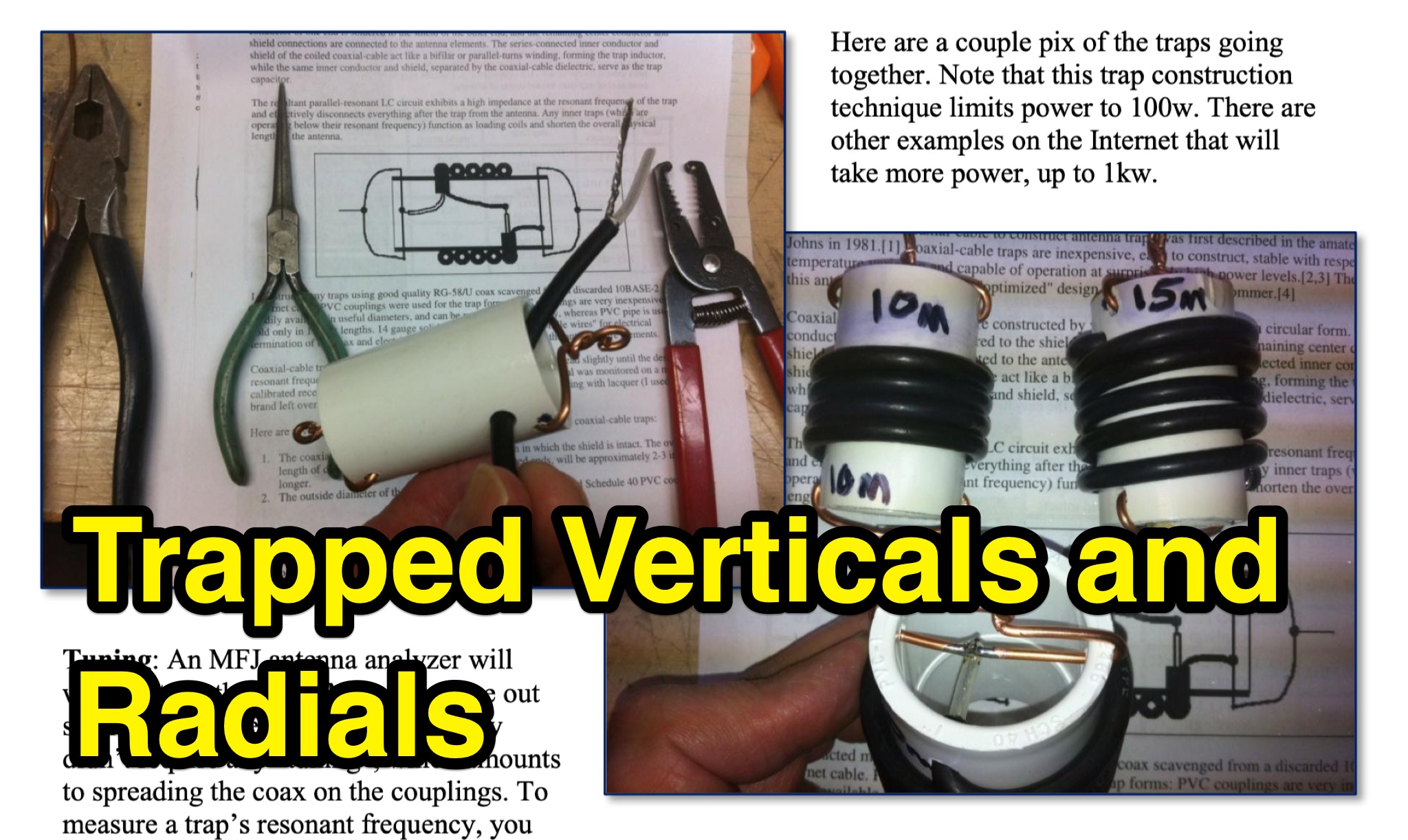 This PDF document provides detailed information on the design, construction, and tuning of trapped vertical antennas with radials for ham radio operators. It covers the theory behind trapped antennas, practical considerations for installation, and tips for optimizing performance. Whether you are a beginner looking to build your first HF antenna or an experienced operator seeking to improve your station setup, this guide offers valuable insights and instructions. By understanding the principles outlined in this document, hams can enhance their operating experience and make the most of their radio communication capabilities.
 -
 Learn how to build your own QRPGuys DS-1 40-10m short vertical antenna for ham radio operators. This page provides detailed instructions on constructing this antenna, which covers the 40 to 10-meter bands. Whether you're a beginner looking to get started with antenna building or an experienced ham radio operator looking for a new project, this resource is useful for anyone interested in DIY antennas for portable or QRP operations.
 -
 Learn how to design a Hentenna antenna, a portable asymmetrical double-loop antenna ideal for amateur HF or VHF bands. This page provides details on constructing and optimizing the antenna for maximum performance in DX communications. Discover how altering the antenna's vertical feed section can adjust the VSWR resonant frequency and how changing the support pole's position can alter the beam direction. Originally developed by Japanese 6-meter operators, the 'Hentenna' offers a unique design that allows for horizontal polarization when vertically oriented. Explore radiation patterns, VSWR charts, and antenna currents diagrams to optimize your antenna's performance for long-distance contacts.
 -
 The 1/4 wavelength vertical antenna project, initially designed for 20 meters, has evolved into a versatile portable solution covering 10 through 60 meters. K0BXB details its construction, emphasizing a bottom-loaded design with a tapped loading coil and four 10-foot counterpoise wires. The author shares personal experiences and field results, including **18 QSOs** during a park activation on 17m and 30m with 10 watts, and a **2,435-mile** contact with a contest station in Bonaire on 20m using 5 watts. Comparisons are drawn to commercial offerings like the _Wolf River Coils TIA_ and _QRPGuys Triband Vertical_, highlighting the DIY antenna's small footprint, light weight, and ease of tuning for POTA activations. The resource includes insights into using test equipment such as the _NanoVNA_ for SWR optimization and discusses various radiator lengths, from 17-foot wire to a 102-inch whip, demonstrating adaptability for different portable setups. Construction tips cover coil winding, tap placement, and connecting feedlines and radials using common components.
 -
 This article presents a novel Top Loaded End-Fed Half-Wave (TLEFHW) antenna design for 20-meter ham radio operation. The antenna features a compact 14-foot vertical radiator with a capacitance hat configuration, eliminating the need for radials or ground systems. Using EZNEC modeling and field testing, the design achieves a 1.5:1 SWR across the 20m band with a 4.11 dBi gain. Key features include quick deployment, lightweight construction, and directional radiation pattern with 110-degree beamwidth. The design, while requiring a 45-foot footprint due to the top hat, offers an effective portable solution for amateur radio operators seeking a no-ground, no-tuner 20m antenna option.
 -
 Fully functional weathervane conceals an efficient 2- meter base-station antenna. Your Neighbors and HOA won’t know it’s there and they will love the rooster-vane. The Rooster-Tenna is a covert 2-meter ham radio antenna disguised as a functional weathervane, ensuring seamless integration into residential environments. This improved version features a wide-spaced parallel-fed folded dipole in a compact skeleton slot design. Constructed from aluminum tubing and acrylic supports, it offers omnidirectional, vertically polarized performance suitable for repeater and satellite use. Easy to mount and tune, it achieves a low SWR across the 2m band. With 3D-printable parts available, the Rooster-Tenna blends practicality with stealth, making it an ideal solution for HOA-restricted areas
 -
 W1JR-style common mode chokes are versatile tools for antenna experimentation. Three variants were constructed using RK4 ferrite cores and RG303 Teflon coax, differing only in output terminals: banana connectors for dipoles, N-connectors for antennas with existing terminals, and bolts with washers for vertical antennas. Materials included junction boxes, terminals, and small hardware. Assembly involves maximizing windings on the core, securing with ties, and gluing components. Improvements included switching to multi-stranded wire for durability. These chokes provide efficient, customizable solutions for various antenna setups.
 -
 Delta loop antennas, particularly the 30 meter variant, offer unique advantages in terms of vertical polarization and omni-directional coverage. The construction process detailed by VE3VN highlights common mechanical and electrical challenges faced by amateur radio operators. Key design considerations include minimizing interaction with existing contest band antennas, achieving low elevation angles for DX chasing, and ensuring the antenna remains off the ground for agricultural clearance. The article provides specific measurements, such as the loop's height and feed point impedance, which are critical for optimizing performance. The use of NEC modeling software illustrates the importance of accurate resonance calculations, revealing how proximity to the tower affects both pattern and impedance. This practical account serves as a resource for hams looking to build effective antennas while navigating typical construction hurdles.
 -
 The K5USS 6 Meter Hentenna Project page on Hamuniverse provides detailed instructions on how to build a 6 meter directional antenna with 3.5 dBd gain. The project is presented with permission from K5USS, Charlie of Richardson, Texas. This directional antenna is a full wave loop on 6 meters, horizontally polarized but mounted vertically, with a 50 ohm impedance, ideal for 6 meter SSB operations. The page is useful for hams looking to construct their own directional antenna for improved performance on the 6 meter band.
 -
 This article demonstrates how to convert an existing tower into a dual-band vertical antenna for 80- and 160-meter DX operation. Using EZNEC modeling and practical design principles, the authors achieved a low-profile, efficient setup with a single coax feed line, no moving parts, and optimal radiation patterns. The system integrates an 80-meter vertical wire and a 160-meter shunt-fed gamma match for simultaneous operation. Detailed construction insights, including feed system and capacitor configurations, offer a reliable, full-legal-power solution.
 -
 This article describes the design and construction of a 4-meter band vertical sleeved dipole antenna, built to complement a newly acquired Yaesu FTDX10 transceiver. The simple yet effective antenna consists of modified coaxial cable housed in weather-resistant plastic conduit, featuring an integrated 8-turn choke coil. Despite common misidentification as an EFHW antenna, this design is actually a sleeved dipole that provides an excellent 50-ohm match across the band, achieving SWR values between 1:1 and 1.1:1. The project demonstrates an economical approach to entering the relatively quiet 4-meter band.
 -
 Details the construction and performance of a phase-controlled receiving array, specifically a **MicroSWA** variant, optimized for QRP low band fox hunting on 40M and 80M. The resource documents the author's iterative design process, addressing significant regional noise challenges encountered during 0100-0230 UTC fox hunt periods. Initial experiments involved a director wire on a 40M vertical, yielding limited improvement, prompting a shift towards advanced null-steering techniques. The project leverages concepts from Victor Misek’s "The Beverage Antenna Handbook" and Dallas Lankford’s extensive work on phased receiving antennas for urban lots. A key modification involved integrating a new passive phase control box and a push-pull **Norton common base preamp** using 2N5109 transistors, designed for high third-order intercept performance to maintain weak signal integrity amidst strong adjacent signals. The system incorporates Faraday-shielded transformers with RG174 primaries on -75 ferrite cores, housed in ABS plastic pipe. Performance tests confirmed the MicroSWA's ability to produce deep, steerable nulls, achieving approximately 30 dB noise reduction on 160M, 80M, and 40M. This enabled detection of QRP signals undetectable on conventional transmit antennas. The final unit includes front panel controls, a 10-11 dB preamp, and a robust power conditioner, demonstrating effective noise mitigation for challenging low band QRP operations.
 -
 The W6PQL 23cm Beacon Project describes a **1296 MHz** beacon designed for microwave propagation studies and equipment testing, capable of 30 watts output. It utilizes a PIC 16F628A microcontroller to generate CW and FSK keying for a crystal oscillator, followed by a series of frequency doublers and triplers to reach the target frequency. The final power amplification stage employs a Mitsubishi M57762 module, providing a robust 10-watt RF output. The design emphasizes stability and reliability for continuous operation, with the microcontroller code, written in assembly, provided for customization of the beacon's callsign and message. Originally located in CM97am and aimed at 140 true, the beacon used four 4-foot Yagis stacked vertically for a total ERP of 3kW. The article includes schematics, parts lists, and construction notes to guide builders, along with antenna pattern measurements. Although the beacon itself is no longer in service as of August 2010, the detailed documentation remains a valuable reference for amateur radio operators interested in building similar **microwave** projects or understanding beacon operation.