Search results
Query: amp
Links: 933 | Categories: 43
Categories
- Manufacturers > Amplifiers
- Technical Reference > Amplifiers
- Technical Reference > Amplifiers > HF Amplifiers
- Radio Equipment > HF Amplifiers
- Operating Modes > Morse code > High Speed CW > HST Championships
- Ham Radio > Clubs > North America > USA > New Hampshire
- Technical Reference > Preamplifiers
- Technical Reference > Amplifiers > RF Amplifiers Theory
- Operating Modes > Mobile > RV & Camping
- Technical Reference > Amplifiers > UHF Amplifiers
- Technical Reference > Amplifiers > VHF Amplifiers
- Radio Equipment > VHF-UHF Amplifiers
- Radio Equipment > HF Amplifiers > Acom 1000
- Radio Equipment > HF Amplifiers > Acom 1010
- Radio Equipment > HF Amplifiers > Alpha 8410
- Radio Equipment > HF Amplifiers > Alpha 87A
- Radio Equipment > HF Amplifiers > Alpha 9500
- Operating Modes > AM
- Radio Equipment > HF Amplifiers > Ameritron AL-80B
- Radio Equipment > HF Amplifiers > Ameritron AL-811
- Radio Equipment > HF Amplifiers > Ameritron AL-811H
- Radio Equipment > HF Amplifiers > Ameritron ALS-600
- Technical Reference > Audio
- Manufacturers > Broadcasting Equipment
- Ham Radio > Clubs > Europe > UK > Central England
- Radio Equipment > HF Transceivers > Elecraft K4
- Radio Equipment > HF Amplifiers > Heathkit SB-200
- Radio Equipment > HF Amplifiers > Heathkit SB-220
- Radio Equipment > HF Amplifiers > Kenwood TL-922
- Operating Aids > Log Formats
-
 Technical reference about Accessories, Amplifiers, Antennas, Cable and Connectors, Filters, Geography, Grounding, Gunk, Matching Networks, Projects, Propagation Info Radios, RFI/EMI, Rotors, Station Setup, Towers.
 -
 You will find on these pages my experiences and results on antennas and local/non-local QRM/noise reduction. Using a broadband vertical active magnetic loop and a home made / designed broadband amplifier. Two vertical magnetic Alford loops are used in an array. Analog and Digital Signal Processing and a dual phase coherent Software Defined Radio (SDR) are used. By PA0SIM
 -
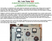
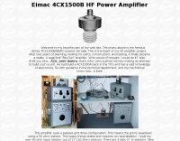 1500 Watt HF power amplifier
 -
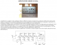 Italian page including pictures schematics diagrams of an home made linear amplifier using four EL509 in parallel. Output power is about 700W.
 -
 Presents Telstar Electronics as a manufacturer specializing in amateur radio accessories, detailing its history since 1995 and highlighting key product offerings. The resource specifically mentions the _VoiceMax Transceiver Speech Processor_, designed to enhance audio fidelity and punch for SSB transmissions, and the _SkyWaveDX350_, indicating a focus on signal processing and reception improvement for DX operations. The company's product categories span ham radio accessories, microphones, and RF amplifiers, catering to various aspects of a station setup. The site implies a direct-to-consumer model for these specialized components, providing technical solutions for Icom, Yaesu, and Kenwood transceivers, and supporting homebrew enthusiasts with components and technical references.
 -
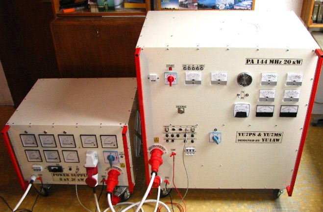 YU1AW project for a home made QRO PA 144 MHz 20 kW GU36B-1
 -
 Source of common model manuals and amateur help on amplifier problems for the amateur bands, Discussion of vacuum tube amplifiers. Technical information and discussion of obselete tube replacement.
 -
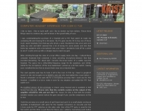
 Constructing a high-power solid-state amplifier for HF operations presents unique challenges, particularly when aiming for significant output like 600 watts. This project details an amplifier design employing **Motorola MRF150** FETs, a common choice for their robust performance in RF power applications. The design emphasizes achieving substantial power output, a critical factor for effective DXing and contesting, where every decibel can make a difference in signal propagation and readability. While specific circuit diagrams or construction details are not directly presented on the current page, the mention of MRF150 FETs points towards a design that would typically involve push-pull configurations, impedance matching networks, and robust power supply considerations to handle the high current demands. Such amplifiers are often built with an eye towards linearity and efficiency across the HF bands. Amateurs pursuing similar high-power solid-state projects often share insights on thermal management, intermodulation distortion, and component sourcing, all vital for a stable and reliable amplifier capable of delivering 600 watts into a proper antenna system.
 -
 Professional tower supplies and specialty products for amateurs and industry.
 -
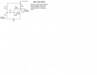
 HF QRP Linear Amplifier with 2x 2SC2166 + 2x 2SC1969 Push Pull Transistors (13.8V)
 -
 The Elecraft K3, a popular HF transceiver, is often benchmarked against new market entrants. This article critically compares the Kenwood TS-590S to the K3, focusing on key technical specifications and operational aspects relevant to serious amateur radio operators. The author proposes three distinct evaluation methods: a circuit diagram comparison, an independent review analysis (referencing Peter Hart, G3SJX, in RadCom), and a real-world "ear test" by experienced contest operators on 40 and 80 meters. The analysis delves into specific receiver components, including the first mixer design, RF and IF amplifier performance, and the presence of an image noise filter. It highlights the K3's switched mixer and the potential for the TS-590S to utilize similar or improved designs, such as a classic filter with enhanced selectivity. The article also scrutinizes the second mixer stage, noting the K3's SA612 chip and its associated IP3 limitations, suggesting Kenwood might achieve benefits with a different mixer architecture. Further points of comparison include DSP capabilities, where the K3's high-performing DSP with KK7P's involvement is noted against the TS-590S's potential reliance on newer IC technology but possibly less refined software. The discussion extends to DDS and PLL implementations for phase noise and spurious emissions, and the utility of a second receiver for DX chasing and contesting, acknowledging its importance for some operators while being less critical for others. The article concludes by emphasizing personal preference in equipment selection.
 -
 Demonstrates the construction of a **homebrew spectrum analyzer** designed by Wes Hayward, W7ZOI, and Terry White, K7TAU, enabling radio amateurs to build a capable test instrument without significant expense. The resource details a _double-conversion superheterodyne_ circuit, employing intermediate frequencies of 110 MHz and 10 MHz, and covers essential blocks such as the time base, logarithmic amplifier, resolution filters, and local oscillators. It highlights the use of hybrid and monolithic ICs, including mixers, amplifiers, and VCOs, to simplify construction while maintaining performance. The design supports useful measurements in the 50 kHz to 70 MHz range, with methods outlined for extending capabilities into VHF and UHF. The authors emphasize that this analyzer, while simple to build, is intended for serious measurements, requiring careful control of signal levels to avoid spurious responses. It uses an oscilloscope for display, with specific instructions for calibration and adjustment of various stages, including the log amplifier and IF gain. The guide provides detailed schematics and component lists for each section, such as the 110 MHz triple-tuned band-pass filter, which achieved **90 dB** image rejection, a significant improvement over double-tuned circuits. Practical advice on alignment and troubleshooting is included, drawing on the authors' extensive experience in RF circuit design.
 -
-
 Mirko Pelcl's extensive radio collection features numerous historical transceivers and receivers, with a significant focus on military communications gear. The collection includes notable examples such as the Wireless Set No. 19, various Cold War-era military radios, and even a rare WWII spy radio utilizing a Loewe 3NF tube. Visitors can explore detailed sections dedicated to sets manufactured before 1945, including those used for military exchange, and a separate category for post-1945 radios, particularly those from the former Yugoslavia. The site also delves into specific modifications, like a digital head conversion for the RU-20, and showcases a frequency counter built with a microcontroller. This personal archive provides a unique glimpse into the evolution of radio technology, from early vacuum tube designs to more modern solid-state military transceivers like the PRC-515. The content reflects Mirko's dedication to preserving and documenting these pieces of radio history.
 -
 Autotena, a Taiwanese manufacturer, offers a diverse product line focused on RF communication antennas and related accessories. The resource details various antenna types, including **4G/3G LTE wideband high-gain low-profile antennas**, land mobile wideband antennas, fiberglass omnidirectional designs, and GPS mobile and marine antennas. Specific amateur radio offerings include NMO VHF load coil gain antennas, VHF whip gain antennas with PL-259 connectors, and UHF NMO mount antennas with 3dB/5dB gain. The company also produces antennas for CB and 10-meter amateur bands, such as aluminum broadband 26-30MHz antennas and big copper coil broadband 26-30MHz antennas. Additionally, the site showcases **RF amplifiers** for CB, HF, VHF, and UHF bands, including professional-grade base station amplifiers with 100% EIA duty cycle. Handheld antennas, PL-259 type mobile antennas, magnet mount antennas, and external CB speakers are also presented, alongside various mounting kits and cable assemblies.
 -
 MC-50 microphone modification for high emphasis, connecto kenwood ts-50 to kenwood radios.
 -
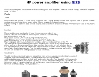 Gi7b is tube designed for microwaves but working good as HF amplifier. Idea is to build cheap, reliable HF amplifier covering 160 meters band.
 -
 Details a practical QRP wattmeter construction, leveraging a simplified SWR meter design by JA6HIC. The project focuses on a forward-only power measurement circuit, providing a functional instrument for RF power levels from milliwatts up to 5 watts. It maintains a 50-ohm input and output impedance, suitable for typical QRP transceivers and antenna systems. The resource includes the schematic for the "VSW" (Very Simple Wattmeter) and outlines a six-step alignment procedure. This calibration process involves using a known RF source up to 5W, setting full-scale deflection, and marking power increments. It also addresses minimizing frequency effects on readings with a 100pF trimmer capacitor, noting that measurement error is highest at the lower end of the scale. Construction notes mention using a piece of RG-213 coaxial cable for the inductance and coupler, with the wattmeter assembled in early 2003. The author provides an example measurement showing 0.8W into a dummy load and 1W into a 3-element beam.
 -
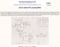 On 23cm the best way to obtain a good RX-sensitivity is to use a GaAs-FET in the front-end, since these devices show very low noise figures.
 -
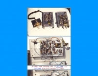
 Repeaters, transmitters, receivers, small power Amps and Controllers
 -
 PA3FWM's software defined radio (SDR) page documents his extensive hardware and software development efforts between 2004 and 2009. Initial experiments utilized a direct conversion receiver with 90-degree phase difference, feeding a PC soundcard at 48 kHz sample rate, covering 24 kHz of spectrum around a 7080.5 kHz local oscillator. This setup, similar to AC50G's QEX 2002 article, allowed for basic I/Q signal processing to distinguish signals above and below the LO frequency. Limitations included fixed crystal frequencies, 16-bit dynamic range, and narrow bandwidth. Subsequent hardware iterations aimed for enhanced performance, incorporating external 24-bit ADCs with 192 kHz sample rates, connected via 10 Mbit/s Ethernet. A **MC145170-based PLL** and programmable octave divider provided a 58 kHz to 30 MHz tuning range. The **Tayloe mixer** was employed, with differential outputs feeding a PCM1804 ADC. An ATmega32 microcontroller handled serial data conversion to Ethernet frames, though without CRC calculation due to processing constraints. Later designs integrated AD7760 2.5 Msamples/second ADCs and a Xilinx Spartan-3 FPGA, enabling direct reception of 0-1 MHz spectrum and eventually 2.5 MHz bandwidth across the shortwave spectrum. Software was refactored to use an initial 8192 non-windowed FFT for efficient high-bandwidth processing. The project culminated in a two-way QSO on 21 MHz using the developed hardware and software, demonstrating transmit capabilities with a D/A converter. The system exhibited a 2.5 MHz wide spectrum display and a zoomed 19 kHz display, capturing signals like ionospheric chirp sounders and RTTY contest activity. Challenges included noise leakage from digital circuitry and cooling for high-power dissipation components.
 -
 RSCW demonstrates a Linux/Unix command-line utility engineered for **Morse code** decoding via a computer's sound card. It specifically targets the extraction of weak CW signals from noise, operating on 8-bit, 8000 samples/second audio input, typically from `/dev/dsp`. The program outputs decoded characters to `stdout`, supporting user-specified speeds in words per minute (WPM) and carrier frequencies. While effective for machine-sent signals, it exhibits a 2-second decoding lag and requires manual speed input, making it less suitable for general-purpose, real-time contest operation. The resource details the program's components, including `rscw` (the main decoder), `rscwx` (an X11 graphical auxiliary for spectrum and internal signal visualization), `rs12tlmdec` (a specialized decoder for RS-12 amateur radio satellite telemetry), and `noisycw` (a utility for generating noisy Morse signals for testing). Installation instructions involve downloading a `.tgz` file, compiling with `Make`, and requiring the FFTW library (and GTK 2.0 for `rscwx`). Performance is illustrated with a .wav file example of a 12 WPM, 800 Hz CW signal at 12 dB Eb/N0, showcasing RSCW's near-error-free decoding of a test message. The site provides command-line examples utilizing `sox` for audio conversion and `noisycw` for signal generation, inviting comparisons with other decoding software and human operators, particularly for weak signal conditions.
 -
 Well documented Amateur Radio HF/VHF antenna projects, high power Russian GS35B RF amplifiers, mobile RFI solutions, related accessories, vintage radios, Six meter equipment, and useful techniques by K8CU are inside.
 -
 "Amateur radio equipement; Procom equipement Duplexeur, amplifier , Coax , connecteur microwave equipement"
 -
 The EF0604S is a compact 4 elements yagi antenna plan for six meters band featuring 8.77 dBi gain and a front back gain of 17.89 dB. Article includes elements dimensions and spacing, along to pictures of some homebrewed examples.
 -
 The Buddipole website showcases a range of portable amateur radio antenna systems, including the **Buddipole**, Mini-Buddipole, Buddistick PRO, and BuddiHEX, designed for rapid deployment and multi-band operation from 40 meters to 2 meters. Each product page details specifications, operational modes (dipole or vertical), and compatible accessories like tripods, masts, and baluns. The site also features portable DC power management systems such as the PowerMini 2 and PowerPlus, which include integrated battery chargers and solar controllers, catering to off-grid or field day setups. Instructional videos demonstrate antenna assembly, tuning, and deployment techniques for various configurations, including the VersaTee vertical and Mini-Buddipole. Customer testimonials and DXpedition highlights, such as operations from Montserrat (VP2M) and Dominica (J38), provide real-world examples of the equipment's performance in challenging environments. The company, established in 2001, emphasizes modularity, versatility, and efficiency in its product line, all manufactured in the USA. Shipping information, a 30-day return policy with no restocking fee, and contact details for their Heber City, Utah facility are clearly presented. The site serves as a direct sales portal, offering a comprehensive catalog of antennas, power solutions, and components for portable amateur radio enthusiasts.
 -
-
 KR1ST computer headset interface for Icom IC-718
 -

-
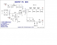 80m hexfet power amplifier by W7ZOI
 -
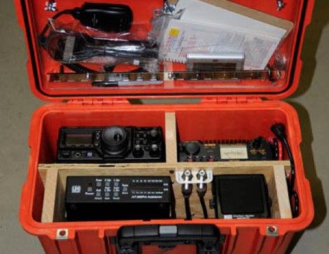 The best way to describe a go-box is a complete amateur radio station in a box. An example is described in this article. The project describes building a portable amateur (ham) radio station, known as a "go-box," housed in a durable orange Pelican case. The go-box contains all necessary radio equipment except for external power and antennae, which are carried separately. It includes items like a Yaesu transceiver, power supply, antenna tuner, speaker, and a clock. The case is designed for mobility and visibility, with a vertical layout to allow in-vehicle operation. Future upgrades might include cooling fans, an LED lamp, and built-in antennae for better functionality in various conditions.
 -
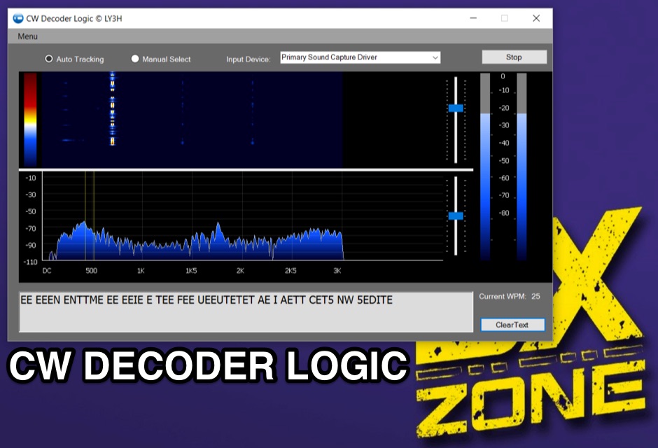 Demonstrates CW Decoder Logic, a freeware application for Windows Vista SP2, 7, 8, and 10, designed to decode Morse code signals. The software incorporates an optimized 80 Hz DSP filter, enabling reception of CW signals across a speed range of 5 to 60 WPM. Key features include automatic signal tracking within a 3 KHz range, real-time speed detection, and an auto squelch function, enhancing decoder sensitivity and accuracy. The application provides station selection directly on a waterfall display and includes a "Tips" feature for word annotations. It supports sending decoded text to external logging software via UDP protocol, with a logger source code example provided for developers. Configuration options allow users to set speed limitations and customize interface elements. Released initially on October 17, 2016, with subsequent updates, the program requires Microsoft .NET Framework 4.5 or higher. Changelogs detail improvements such as increased program stability, code optimizations for speed, and fixes for display issues across different Windows versions.
 -
 Amateur radio accessories, power supplies, tvi filters, speakers, microphones, swr meters, preamplifiers, switches, cable and connectors,
 -
 Sams Photofact downloads - Schematics and Service Manuals for Radios, Amplifiers, More
 -
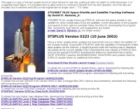 STSORBIT PLUS, usually known as STSPLUS, will track the space shuttle or any satellite for which orbital data (TLEs) are available. A brief description of the program and several screen capture examples follow the links for downloading the program files.
 -
 Publication for the video aspects of ham radio
 -
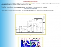
 Advanced QRP Low Cost Mosfets HF Linear Amplifier with schematics, IMD, gain data and more. Six articles about amateur radio.
 -
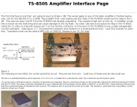 An interface for amplifier to TS-850S
 -
 I4FAF etrode Tube Linear Amplifier experience
 -
 Illustrates the global distribution of **DX-Cluster** nodes through an interactive map interface, enabling radio amateurs to visualize and access real-time DX spots. The resource provides direct TELNET and HYPER links for each node, facilitating immediate connection to various clusters for up-to-the-minute propagation information and station activity. This visual approach simplifies the process of locating and connecting to a suitable DX-Cluster, whether for local or international DXing. Amateurs can use this tool to quickly identify active clusters in different geographic regions, which is particularly useful for **DXpedition** planning or contest operations. The direct links streamline access, bypassing manual configuration for many cluster types. It serves as a practical aid for operators seeking to monitor band conditions, find rare DX, or participate in competitive operating events by leveraging aggregated spotting data.
 -
-
 Bill Orr W6SAI ham radio techniques. Improving ground connection, computer analysis of the antenna, modelling sample antennas pdf file
 -
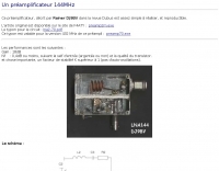 A preamplifier project based on Rainer DJ9BV project, in french
 -
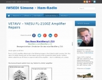 The FL-2100Z amplifier referenced in the following images is the 6-Band model covering 10m thru 160m (no WARC bands) and not the 9-Band version that included the WARC bands. Modifications, schematics and manual
 -
 ON6MU optimized 6/9 element vhf yagui antenna with antenna schematic plan and pictures of homebrewed samples.
 -
 Pictures and circuit diagramm to build this power amplifier for 2 meters
 -
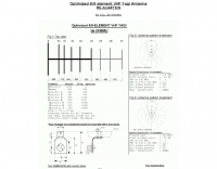
 The document details the optimization and construction of the _Maria Maluca_ antenna, a compact 6-band (20m-6m) directional beam. It presents a comparative analysis of shortwave antenna principles, highlighting the efficiency gains achieved by using an open feeder line and tuner as a resonant unit, contrasting this with the losses associated with traps or capacitive loads in multiband antennas. The resource specifically revisits an older South American 2-element design for 10, 15, and 20 meters, applying modern NEC-based software to develop a six-band version. Performance data is meticulously tabulated, showing impedance, free space gain, gain at 12m height, elevation angle, and front-to-back (F/B) ratio for each band from 20m through 6m. For instance, on 15m, the antenna achieves 5.1 dBd free space gain and 13.72 dB F/B ratio. The construction section provides practical guidance on element assembly using aluminum pipes and hose clamps, detailing the use of a heavy-duty glass fiber reinforced polyamide rod for electrical separation and bending strength. It also specifies the use of 450-ohm _Wireman_ line CQ 552 for the transmission line. The document includes diagrams for rod fixing, an air-wound balun, and a vertical elevation diagram for the 15m band, illustrating its DX qualification. It also discusses the antenna's suitability for portable and expedition operations, noting its compact transport dimensions (max 1.50m length, 12 lb weight) and quick assembly time (under 15 minutes). The author, Dipl.Ing. Helmut Oeller, DC6NY, is identified as a source for material kits.
 -
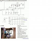
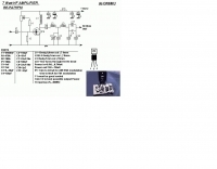 An RF power amplifier, providing 7 Watts output in HF bands, schematic by ON6MU
 -
 Electronic circuit and components layout fot this VHF Preamp