Search results
Query: foot
Links: 121 | Categories: 0
-
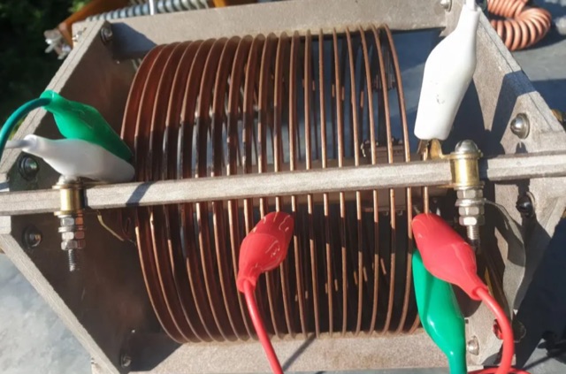 A transmitting antenna 2x15m, about 100 foot doublet antenna fed by a ladder line of about 600 Ohm. Article in Polish and English,
 -
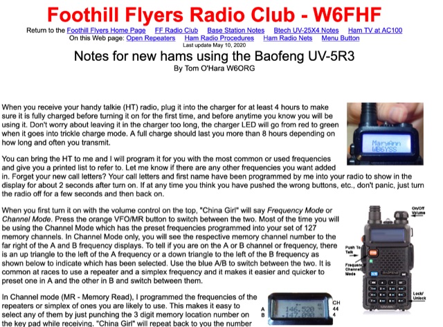 Notes for new hams using the Baofeng UV-5R3, Basic Ham Procedures, open repeaters, Local Ham Nets.
 -
 Showcasing German engineering, ANjo Antennen develops and manufactures a diverse portfolio of amateur radio and commercial antenna products. Their offerings span a wide frequency range from 1.8 MHz to 3000 MHz, emphasizing electrical and mechanical precision for longevity. The company actively participates in events like FUNK.TAG Kassel, providing opportunities for direct engagement and order pickup. ANjo's product line includes high-performance **Yagi antennas** optimized for Tropo and EME, along with multi-stacked Quad antennas designed for contest operations, featuring wide horizontal and narrow vertical beamwidths. They also produce circularly polarized satellite antennas, some with switchable LHCP/RHCP, leveraging their commercial satellite antenna expertise. Beyond amateur applications, ANjo provides flexible, custom antenna solutions for commercial sectors such as BOS, EMC measurements, and telemetry. Their commitment to quality is evident in the Premium-Line antennas, which utilize **1.4301 (V2A) stainless steel** for mast clamps and connectors, ensuring durability and corrosion resistance. They also offer end-fed HF multiband wire antennas, known for their compact footprint and discreet installation.
 -
 The article describes a high-gain, compact beam antenna design for the 2-meter band (144-146 MHz). The NSH 4x4 Boomer is a 4-element antenna that is mounted on a 4-foot boom with an 8.2 dB gain, 1.2:1 SWR, and a front-to-back ratio of 18 db. It is designed for mobile operations and little area, making it perfect for field usage such as disaster management. The design employs regularly spaced parts with a straightforward gamma match for tuning, and the construction materials include a square boom and polished aluminum tubes. In local and portable tests, the antenna worked regularly, achieving contact distances of up to 15 kilometers.
 -
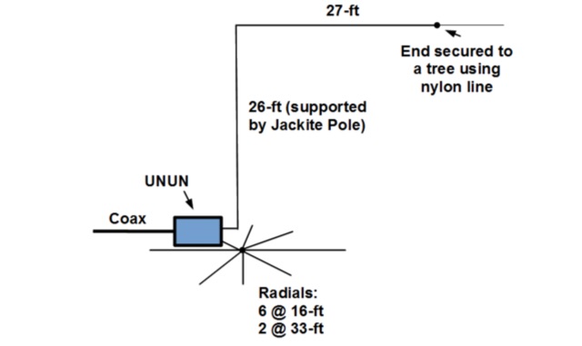 Inverted L antenna, even if not completely freestanding, it only requires one line to be lauched into a tree to support the end of the horizontal wire. This project is done with a 31-foot Jackite pole for a support and uses six 15-foot radials and one 33-foot radial.
 -
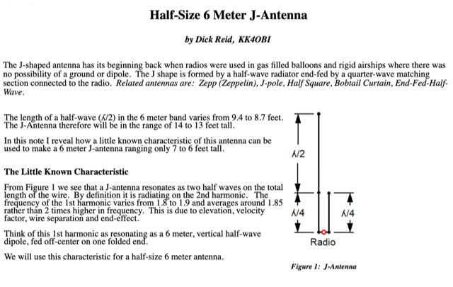 How to use a little known J-antenna characteristic to reduce a conventional 14 foot antenna to 7 feet. Perfect 50 Ohm match, same gain, no radials.
 -
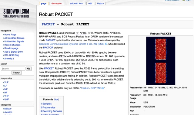 Robust PACKET, developed by Spezielle Communications Systeme GmbH & Co. KG (SCS), is an OFDM variant of the amateur PACKET mode specifically engineered for HF operation. This mode utilizes a 500 Hz bandwidth with 60 Hz carrier spacing, employing OFDM with 8 DBPSK or DQPSK carriers. It supports 200 bps using BPSK and 600 bps with DQPSK, with each subcarrier operating at a constant rate of 50 Bd. Robust PACKET leverages the AX-25 frame protocol for data transmission, similar to standard PACKET. Compared to traditional PACKET, Robust PACKET demonstrates enhanced resilience against multipath propagation and fading effects, critical for reliable HF communications. It also exhibits a more efficient spectral footprint, with sidebands extending only to 500 Hz, whereas 300 Bd FSK PACKET can produce sidebands up to 730 Hz. Operational frequencies for Robust PACKET include 3.61 MHz, 7.0473 MHz, 10.1473 MHz, and 14.1033 MHz, with specific regional frequencies also documented. Decoding software options for Robust PACKET include Wavecom W-Code and Wavecom W-Spectra. The mode is primarily supported by SCS's 'Tracker / DSP TNC' hardware.
 -
 This article details the development of an 80-meter antenna within the confines of a restrictive covenant community. Faced with limited space, the author explores various options before implementing a clever hybrid design: a short 30-foot vertical wire running discreetly down the building's exterior combined with a capacitive top hat installed in the attic. Computer modeling confirmed the superiority of capacitive loading over inductive loading, increasing radiation resistance from 6 to 14 ohms. The perimeter wire top hat, naturally supported by the attic structure, resonates effectively at 3.5 MHz. The system is completed with four buried 60-foot radials installed "after dark" to maintain compliance with community restrictions.
 -
 Medium power BMU (Base Matching Unit) intended for 42 foot to 48 foot vertical, sloper, or Inverted-L antennas.
 -
 The 1/4 wavelength vertical antenna project, initially designed for 20 meters, has evolved into a versatile portable solution covering 10 through 60 meters. K0BXB details its construction, emphasizing a bottom-loaded design with a tapped loading coil and four 10-foot counterpoise wires. The author shares personal experiences and field results, including **18 QSOs** during a park activation on 17m and 30m with 10 watts, and a **2,435-mile** contact with a contest station in Bonaire on 20m using 5 watts. Comparisons are drawn to commercial offerings like the _Wolf River Coils TIA_ and _QRPGuys Triband Vertical_, highlighting the DIY antenna's small footprint, light weight, and ease of tuning for POTA activations. The resource includes insights into using test equipment such as the _NanoVNA_ for SWR optimization and discusses various radiator lengths, from 17-foot wire to a 102-inch whip, demonstrating adaptability for different portable setups. Construction tips cover coil winding, tap placement, and connecting feedlines and radials using common components.
 -
 A 13-foot total radiating element length is achieved by combining a Buddipole Long Telescopic Whip with 4 feet of modified tripod tubes, forming a low-profile, multiband antenna for **POTA** operations. The resource details the transformation of an Amazon Basics Aluminum Light Photography Tripod Stand, focusing on electrically isolating the top two radiating sections from the bottom support. John, VA3KOT, outlines component sourcing, including the 9-foot 4-inch fully extended whip, and emphasizes using adhesive copper tape for reliable electrical contact and conductive grease to prevent oxidation at tube connections. The construction process, while not requiring specialized tools, highlights careful assembly to ensure proper electrical conductivity and mechanical stability. The author's experience with this setup suggests its effectiveness for portable activations, offering a discreet profile compared to larger antenna systems. The design prioritizes ease of deployment and transport, making it a practical solution for operators seeking a compact yet versatile antenna for field use.
 -
 The article by Guy Olinger, K2AV, published in the May/June 2012 National Contest Journal, introduces the Folded Counterpoise (FCP), a compact 516-foot single-wire counterpoise elevated at 8 feet, designed for 160-meter operations on small lots like 100x150-foot backyards. Originating from efforts to revive Top Band for W0UCE on a postage-stamp property, the FCP uses strategic folds to cancel ground fields within 33 feet of center, minimizing losses to 0.13-0.53 dB—outperforming sparse or on-ground radials by up to 15 dB in poor soil—while mimicking opposed radials for efficient feedpoint impedance. Paired with a critical 1:1 or 4:1 isolation transformer (e.g., trifilar on T300-2 toroid) to block common-mode currents on coax feeds, it delivers proven results: K2AV's #8 North America low-power contest score, 7+ dB gains at W4KAZ and K5AF, and over 10,000 global web hits for DIY instructions using bare 12 AWG wire and weatherproof enclosures. Ideal for acreage-challenged hams, the FCP also excels on 80 meters with scaled dimensions, offering a low-loss alternative where full radials are impractical
 -
 This article presents a novel Top Loaded End-Fed Half-Wave (TLEFHW) antenna design for 20-meter ham radio operation. The antenna features a compact 14-foot vertical radiator with a capacitance hat configuration, eliminating the need for radials or ground systems. Using EZNEC modeling and field testing, the design achieves a 1.5:1 SWR across the 20m band with a 4.11 dBi gain. Key features include quick deployment, lightweight construction, and directional radiation pattern with 110-degree beamwidth. The design, while requiring a 45-foot footprint due to the top hat, offers an effective portable solution for amateur radio operators seeking a no-ground, no-tuner 20m antenna option.
 -
 The LKJ Wednesday Night Special Antenna, designed by John Whiteman K5LKJ, is a compact 50-foot coil-loaded dipole for 80-meter operation, ideal for space-limited hams in residential areas. Using two 1-inch diameter PVC coils with 87 turns of #16 magnet wire each—placed 10 feet from the center—it tunes to 3.910 MHz for local nets like BVARC Rag Chew. Constructed with #14 wire, ceramic insulators, and Mini-8X feedline, it handles 1000W, performs well at low heights for NVIS, and requires a tuner for bandwidth. Collaborative tuning by club members ensured success.
 -
 The Aziloop DF-72 antenna system provides 72 K9AY headings and 36 loop axes, allowing for rapid switching in 60 ms. It integrates a switchable 18 dB preamp, a 4-step attenuator (0-18 dB), and four 7-pole preselection filters to optimize receiver performance. The K9AY load is adjustable from 250 Ohm to 950 Ohm in 50 Ohm increments, offering flexibility for various receiving conditions. Control is managed via an intuitive Windows UI, supporting Local, Client, or Server modes, with headless remote operation possible through the built-in Ethernet Server. _Omni-Rig_ support facilitates auto-filter selection, PTT muting, and Rig-Sync functionality, enhancing integration with existing station setups. Designed by _GW4GTE_, the system utilizes a low visual impact, small-footprint antenna with orthogonal loops and an earth connection. It is suitable for general monitoring, co-channel station resolution, basic direction finding, and interference reduction across the VLF to HF spectrum.
 -
 John Lemay’s (G4ZTR) review of the Yaesu FT-847 offers a practical look at this all-mode transceiver, spanning 160m to 70cm, including 4m. While it falls short in dynamic range and sensitivity, its "shack-in-a-box" design shines for VHF DXing and multi-band use. Lemay shares hands-on tweaks, like calibrating 70cm with beacons and integrating footswitches for SSB and CW. The TX Inhibit feature simplifies sequencing with external gear. Despite minor flaws, the FT-847’s versatility and mod-friendly nature make it a solid pick for amateur radio enthusiasts craving flexibility.
 -
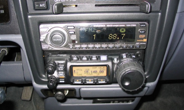 Detailing a Yaesu FT-857 and ATAS-120 installation in a 1997 Toyota Tacoma, the author used Polar Plot to map signal strength. Using a hand truck with a laptop, FT-817, and an Iron Horse antenna, they circled a chalk-outlined 100-foot diameter, revealing potential nulls towards the truck's rear and through the cab, offering insights into antenna performance.
 -
 VE1ZAC's analysis details the performance of **MFJ927** and **SGC239** autotuners with portable HF vertical antennas, specifically comparing 31 ft and 43 ft configurations. The resource originated from challenges encountered during a Maritime QSO Party roving operation, necessitating a lightweight and easily deployable antenna system. Target bands for the contest included 80, 40, 20, 15, and 10 meters, with a maximum power handling of 100 W CW. The author utilized a 30-foot carbon fiber push-up pole to support a vertical wire element, noting its 2 lb weight and reliability. EZNEC modeling was employed to predict performance, showing favorable results for a 30-foot vertical with elevated radials, particularly on 40 and 20 meters. Feedpoint impedance measurements, taken with an AIM4170C, are presented for various HF bands, both with and without a 41-foot RG6 stub designed to reduce reactance on 80 and 20 meters. The stub significantly improved matching on these bands, easing the tuner's workload. Operational tests revealed issues with the MFJ927's reliability during contest setup, leading to reliance on the K3's internal tuner. The SGC239, tested post-contest, performed flawlessly. A detailed side-by-side comparison covers mechanical aspects, connection options, power bias, impedance range, board quality, and documentation. Modifications to the MFJ927, including a new aluminum case, white paint for heat reduction, and upgraded impedance-measuring resistors, are also described.
 -
 Early 20th-century transatlantic wireless communication efforts involved distinct technical approaches by Reginald Fessenden and Guglielmo Marconi. Marconi's systems, operational until approximately 1912, primarily utilized _spark technology_ for wireless telegraphy, facilitating Morse code communication between ships and across oceans. His Poldhu station in December 1901 radiated signals in the MF band around 850 kHz, later evolving to 272 kHz in October 1902, and eventually 45 kHz by late 1907 with increasingly larger antenna structures like the pyramidal monopole and capacitive top-loaded arrays. Fessenden, conversely, focused on _continuous wave transmission_ for wireless telephony, recognizing its necessity for speech. His transatlantic experiments in 1906 employed synchronous rotary-spark-gap transmitters and 420-foot umbrella top-loaded antennas at Brant Rock, MA, and Machrihanish, Scotland, tuned to approximately 80 kHz. Fessenden later utilized the _Alexanderson HF alternator_ at 75 kHz by late 1906 for pure CW transmission, integrating a carbon microphone for amplitude modulation. Receiver technology also differed, with Marconi initially relying on untuned coherer-type detectors, later developing the magnetic detector in 1902, while Fessenden's CW approach necessitated more advanced detection methods.
 -
 The W6PQL 23cm Beacon Project describes a **1296 MHz** beacon designed for microwave propagation studies and equipment testing, capable of 30 watts output. It utilizes a PIC 16F628A microcontroller to generate CW and FSK keying for a crystal oscillator, followed by a series of frequency doublers and triplers to reach the target frequency. The final power amplification stage employs a Mitsubishi M57762 module, providing a robust 10-watt RF output. The design emphasizes stability and reliability for continuous operation, with the microcontroller code, written in assembly, provided for customization of the beacon's callsign and message. Originally located in CM97am and aimed at 140 true, the beacon used four 4-foot Yagis stacked vertically for a total ERP of 3kW. The article includes schematics, parts lists, and construction notes to guide builders, along with antenna pattern measurements. Although the beacon itself is no longer in service as of August 2010, the detailed documentation remains a valuable reference for amateur radio operators interested in building similar **microwave** projects or understanding beacon operation.
 -
 TX5EU 2026 DXpedition to Raivavae Island, **OC-114**, within the Austral Islands, providing a detailed account of the German/Dutch team's operations. The resource outlines the participation of operators such as DL2AWG Guenter, PA2KW Evert, and DK2AMM Ernoe, who engaged in CW, SSB, RTTY, and various digital modes. It documents the real-world challenges encountered, including significant equipment failures and antenna damage to 80/60m, 30m, and 10m verticals due to adverse storm conditions. The page offers timely news updates on the expedition's progress, noting repairs to a power amplifier's 10/12m bandpass filter, which enabled three stations to utilize amplification. Earlier reports highlighted power failures and the loss of multiple power amplifiers, necessitating one station to operate barefoot FT-8 with 100W. The team's persistent efforts to repair antennas as weather permits are also detailed, reflecting the dynamic nature of remote island operations.