Search results
Query: irc
Links: 495 | Categories: 21
Categories
- Operating Modes > Aircraft scatter
- Software > Aircraft scatter
- Software > Circuit Design
- Technical Reference > Mircrowave
- Software > ACARS
- Radio Scanning > Aeronautical
- Technical Reference > Batteries
- Technical Reference > Batteries > Battery Charger
- Technical Reference > Electronics
- Manufacturers > Test Equipment > Impedance Analyzers
- DX Resources > QSLing > International reply coupons
- Technical Reference > Morse Code Oscillator
- Technical Reference > Test Equipment > Multimeter
- Software > PCB Design
- Technical Reference > Receiver Front-End Protector
- Software > RF Design
- Technical Reference > Soldering and Desoldering
- Technical Reference > Transverters
- Technical Reference > Vacuum tube
- Software > Vector Network Analyzer
- Shopping and Services > Antennas > VHF Antenna
-
 Constructing a functional spectrum analyzer for the 0-100 MHz range presents a significant challenge for radio amateurs, often requiring specialized components and careful calibration. This project details a homebrew spectrum analyzer design utilizing common integrated circuits like the _SA605D_ FM receiver IC and _MAR-6_ MMIC amplifiers, aiming for a cost-effective solution. The design incorporates a low-pass filter, RF amplification, a voltage-controlled oscillator (VCO) for downconversion, and multiple IF stages at 150 MHz and 10.7 MHz, with a resolution bandwidth (RBW) of 15 kHz. Critical components such as the _SBL-1_ mixer and varicap diodes are specified, alongside instructions for winding inductors and tuning filters. The analyzer's performance is discussed in terms of input level limitations, specifically the 1dB-compression point and third-order intercept point, to ensure accurate measurements and prevent component damage. The _SA605D_'s logarithmic Received Signal Strength Indicator (RSSI) output serves as the detector, driving the Y-input of an oscilloscope, while a _TL084_ op-amp generates the sweep signal for the X-input. Potential enhancements include adding a step attenuator, improving front-end filtering, and implementing switchable IF filters for variable RBW, allowing for greater versatility in analyzing RF signals.
 -
 A circuit that connects an IBM compatible personal computer, running TR Log or CT (etc.) contest logging software, and Kenwood transceivers equipped with serial control ports. CW keying is also provided in this RFI filtered interface unit.
 -
 Helical antennas invented by John Kraus give a circular polarized wave. They are one of the easiest to design. Find a tube with a circumference equal to one wavelength, and wrap wire in a helix spaced a quarter wavelengt
 -
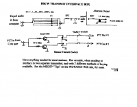
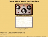 This circuit provides an interface between the Yaesu 920 transceiver and IBM computer sound card which allows data transfer and control of PSK31, RTTY, KEYBOARD CW, and SSTV modes for Amateur Radio
 -
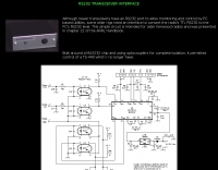 This page displays a 404 error, indicating the original content describing a simple _RS232 interface_ circuit is unavailable. The circuit was reportedly designed for older Kenwood transceivers and featured in chapter 22 of the _ARRL Handbook_. It likely involved basic electronic components for level shifting and signal conditioning between a computer's serial port and the radio's control interface. The intended project would have detailed the construction of a hardware interface, enabling CAT control for specific Kenwood models. Such interfaces typically convert TTL or CMOS logic levels from the radio to the +/-12V levels required by RS232, often utilizing ICs like the MAX232 or discrete transistor circuits. While the specific schematics and bill of materials are absent due to the page error, the context suggests a DIY electronics project for enhancing legacy amateur radio station functionality through computer control.
 -
 FAR Circuits is exclusively a manufacturer of Printed Circuit Boards for electronic projects that are used by the Amateur Radio and electronic hobby enthusiast.
 -
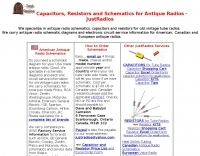 Specializes in antique radio schematics and capacitors. carries antique radio schematic diagrams and electronic circuit service information for american, canadian and european antique radios.
 -
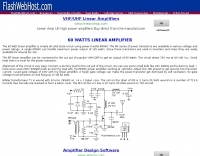 The 60 Watt linear amplifier is simple all solid state circuit using power mosfet IRF840.
 -
 Article on radiation patterns of small loops, equivalent circuits of loop antenna, small loops as receiving antennas, ferrite loops
 -
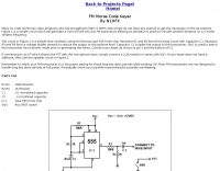 A simple circuit which will generate a 700 Hz tone into any FM transceiver allowing an amateur to practice CW with another amateur on a 2 meter simplex frequency.
 -
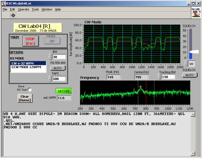 Deciphering weak or noisy **CW** (Continuous Wave) signals often presents a challenge for amateur radio operators, particularly in contest environments or during DXpeditions. CWLab04X addresses this by providing a software solution that leverages **DSP** (Digital Signal Processing) capabilities of a soundcard to decode Morse code. It functions as both a receiver and a sender, supporting traditional CW and a unique "CCW" mode designed to enhance copyability of signals struggling against high noise floors. The program offers two installation methods: a Windows-specific installer for straightforward setup or a zipped package compatible with Windows and Linux systems running Wine. Users must first download and review the accompanying PDF documentation, CWLab04.pdf and CWLab04_Hardware.pdf, which detail the software's operation and the necessary soundcard interface circuit. The hardware PDF outlines a direct connection from the receiver audio output to the soundcard input, with optional conversion of the soundcard output for hard-keying or microphone input. CWLab04X is intended as an operational aid rather than a replacement for skilled human copy, particularly highlighting the effectiveness of its CCW mode in adverse signal conditions. The software was last revised in April 2009, with installation requiring the LV Runtime 602.
 -
 Projects and design atv de ik1hgi Progetti, circuits, master, fotos in Italian
 -
 This article describes a loop usable from 7 - 21 mHz, using half inch copper tube 3 feet in circumference
 -
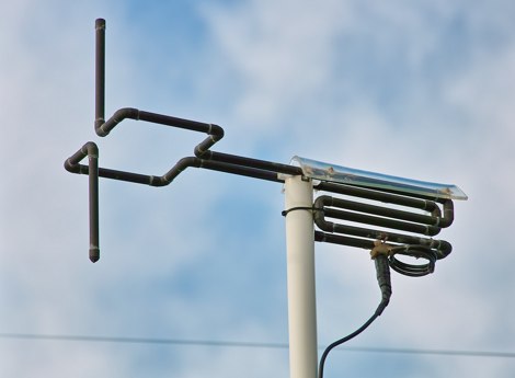
 The antenna is a vertical dipole, around which four parasitic elements are forming a circle.
 -
 For radio amateurs seeking compact and efficient antenna solutions, particularly for restricted spaces or noise reduction, HF loop antennas present a viable option. This resource compiles several articles from the ARRL, detailing the theory, design considerations, and practical construction of various loop configurations. Topics include small transmitting loops, receiving loops, and multi-band designs, often emphasizing their performance characteristics such as directivity, bandwidth, and impedance matching. The collected articles provide insights into the comparative performance of different loop geometries, such as circular versus square loops, and discuss the impact of conductor size and tuning methods on efficiency. Practical applications are explored, including their use in portable operations, stealth installations, and urban environments where noise mitigation is critical. The content often includes construction diagrams, parts lists, and performance data derived from modeling or field tests, enabling hams to replicate or adapt the designs for their specific operating conditions.
 -
 The IC-746PRO is a great rig. But it has a few reliability issues, especially with the earlier-production units. This article addresses four problem areas:. IC151 on the RF Unit. Driver circuit on the PA Unit. HRX-muting circuit on the CTRL Unit. Predriver on the PA Unit.
 -
 A 2 meter antenna made of copper tubes, offering circular polarization
 -
 Helical antennas have long been popular in applications from VHF to microwaves requiring circular polarization, since they have the unique property of naturally providing circularly polarized radiation. Paul Wade W1GHZ
 -
-
 Examines the historical landscape of "boat anchor" amateur radio equipment manufacturers, focusing on the technical innovations and market dynamics that shaped the industry from the pre-WWII era through the transition to SSB. It details the origins and key product lines of prominent U.S. companies like _Collins Radio Company_, _Central Electronics_, and _Barker & Williamson_, highlighting their contributions to receiver and transmitter design. The resource contrasts early AM technology with the advent of SSB, explaining the circuit changes required in receivers and the complete rethinking needed for transmitters. It discusses the impact of military contracts on company survival and the eventual shift towards smaller, self-contained transceivers. Specific examples, such as the _Collins R-390/URR_ receiver and the _Central Electronics 100V/200V_ broadband transmitters, illustrate the engineering prowess and design philosophies of the era, offering insights into their operational characteristics and enduring appeal among collectors.
 -
 Some beginners guide to monitoring aircraft communications
 -
 CTCSS Decoder and Encoder, DTMF Decoder projects
 -
 This resource, "Transistor Audio Preamplifier Circuits," offers comprehensive design guidelines for constructing **bipolar transistor** audio preamplifiers. It delves into critical aspects such as quiescent current setting, voltage gain calculation, and the impact of various component choices on circuit performance. The content provides several _schematic diagrams_ illustrating different preamplifier configurations, including single-stage common emitter and two-stage designs, alongside explanations of their operational characteristics and practical implementation considerations. The analysis extends to frequency response, noise performance, and distortion, providing insights into optimizing these parameters for specific audio applications. The resource presents calculated gain figures for various stages, demonstrating how to achieve desired amplification levels. It also discusses the importance of proper power supply decoupling and input/output impedance matching, crucial for integrating these preamplifiers into larger audio systems or ham radio transceivers. The practical application of these designs is evident in their suitability for microphone preamplifiers or general-purpose audio amplification.
 -
 This web based application will compute circuit values required for an L-C circuit to resonate at given frequency. Also it will compute the resonant frequency if given values for L and C.
 -
 Demonstrates the construction and measurement of a single-turn HF receiving loop antenna, built from common materials like electrical conduit and lamp cord. The resource details the physical dimensions, including a 4-meter circumference, and calculates the theoretical inductance at approximately _6.4 uH_. It outlines a method for determining resonant frequencies across the 4-17 MHz range using a _C Jig_ and a _VR-500 receiver_, coupling the loop with a ferrite ring. The article also discusses the impact of receiver coupling on the loop's Q factor, noting a degradation in sharpness due to the transformer's reflected impedance. Analyzes the observed resonant frequency patterns, highlighting an unexpected rise in the loop's effective inductance at higher frequencies, particularly above 13 MHz. While some increase is attributed to distributed capacitance, the rate of rise suggests further investigation. The experimental setup provides practical insights into the challenges of maintaining high Q in simple receiving loops and offers a comparative reference for other homebrew antenna projects, such as those by _VK2TPM_.
 -
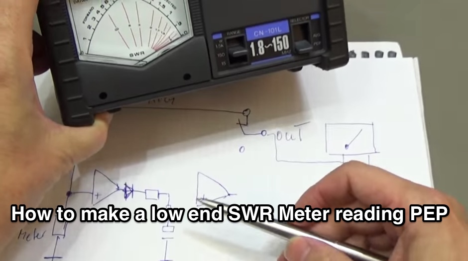 Building a PEP Power circuit for all analogue watt-meter
 -
 HAMIC, is a program designed to simplify a number of calculations commonly used by HAMs. It is designed for the HAM radio hobbyist, but may be useful to others as well. HAMIC has a simple to use, but powerful graphical interface that allows solving simple circuits such as resistors in series or parallel, or more complex circuits such as L networks or T networks. As well, other calculations such as SWR and reactance conversions are supported. Windows shareware.
 -
 Circuit diagrams drake tr7, Schaltbilder Drake Tr7, antenna tuners, baluns, and home brew power supplies, dual tone ssb test generator, zweiton ssb test generator, zweiton testgenerator, dual tone test generator by DK4DDS
 -
 It is a application which can be used for troubleshooting CB radio faults, by giving a graphical display of the normal operating frequencies generated by various parts of the CB radios circuits, it can help you identify if a frequency is incorrect or even missing. Another good use for this software is simulating possible frequency expansions, as it allows you to choose any frequency that the PLL is capable of generating, so you can see what the radio will allow you to get !
 -
 Analog circuit simulator for Windows (not a SPICE). A great tool for students, amateurs, as well as for experienced engineers. Free Demo.
 -
 The circuit is based on two AD8307 log amplifiers, which are connected to the forward and reflected ports on a directional coupler
 -
 FAR Circuits is exclusively a manufacturer of Printed Circuit Boards for electronic projects that are used by the Amateur Radio and electronic hobby enthusias
 -
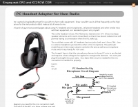 A PC headset to Rig adapter. Include a circuit diagram and a full part list for the project
 -
 Design guidelines for Op Amp audio preamplifier circuits by Mike Martell N1HFX
 -
 Details Guglielmo Marconi's foundational contributions to radio communication, highlighting his 1898 Patent **7777** which introduced tuning circuits for independent simultaneous communications. Chronicles the historic transatlantic reception of the Morse code letter 'S' on December 12, 1901, from Poldhu, Cornwall, to St. John's, Newfoundland, a distance of over _3,500 kilometers_. The exhibit showcases early Marconi 10-inch spark transmitters, identical to those used on the _Titanic_, alongside Canadian Marconi crystal detector models. It also features high-end commercial receivers like the IP501, weighing **87 pounds** and originally priced at $595.00, demonstrating the robust construction and technological advancements of the era.
 -
 SimSmith is a highly interactive, real time Smith chart graphing program. Circuits are constructed using drag-n-drop. Load files can be imported from the EZNEC and CocoaNEC antenna simulation software and from the AIM4170 and miniVNApro antenna analyzers. Circuits and load files can be of any size. Key Features: SimSmith is one of the few Smith chart packages which models transmission line losses. SimSmith also allows the description of circuit elements using algebraic equations. SimSmith has only one screen and allows the screen to be resized to increase workspace or readability.
 -
 The circuit described below will substantially reduce or completely eliminate interference from almost any local source whilst leaving the wanted signal relatively unaffected, even though it may be on the same frequencey by TREVOR, G3ZYY
 -
 The document is a technical guide on designing RF filters for radio frequency applications. It covers topics such as interference suppression, band-pass filters, and low pass filters, with a focus on filter design and circuit filters.
 -
 The Collins TRC-75 autotune linear amplifier, owned by JF2SVU, is presented with a focus on its internal modifications. This QRO amplifier utilizes three 4CX250 tubes in parallel for its final stage, delivering 1 KW output power. Notably, the amplifier achieves full power with only 100 mW of RF input, a characteristic often associated with Collins designs. The original 400 Hz power supply has been converted for easier shack integration, and the entire RF and power supply sections have been rehoused into a compact, clean enclosure. The control unit, positioned above the amplifier, features three meters for individual vacuum tube IP monitoring and a multi-meter on the right. A dedicated 7 MHz receiver, recently completed, is also part of this integrated system. The autotune functionality means the main amplifier unit only requires connections for power, control, and coaxial cables, simplifying its operation. Key components like the 4CX250 tubes and NF capacitors are visible, along with the gearing mechanism for the final tank circuit. A timer and relay system manages high-voltage delay and cooling fan off-delay, although the cooling fan's airflow is noted as somewhat insufficient. A central volume control, which experienced a contact issue, is also highlighted.
 -
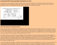
 Minimal interface circuits for receiver and transmitter audio, also for PSK31
 -
 Wikipedia page about regenerative circuits in designing receivers.
 -
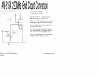 AM-6154 222MHz grid Conversion Information by N0UK
 -
 Frequency database for Germany. Emergency services, aircrafts, radio and paging system with over 2000 frequencies from all over Germany.
 -
 A circuit which had been used in many other application before. The configuration described here is optimized for IPHONE/radio operation.
 -
 The digital wattmeter project was created for the purpose of measuring power in the range of 300nw to 30w.
 -
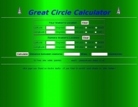 A javascript online calculator of bearing and distances by G4VWL
 -
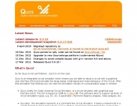 Qucs, briefly for Quite Universal Circuit Simulator, is an integrated circuit simulator which means you are able to setup a circuit with a graphical user interface (GUI) and simulate the large-signal, small-signal and noise behaviour of the circuit. After that simulation has finished you can view the simulation results on a presentation page or window. Run on Linux.
 -
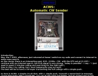 Simple circuit, with a simple push, transmit a memorized Cw messages
 -
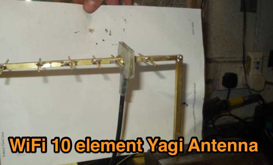 A DIY project of a WiFi 10 elements Yagi antenna
 -
 This circuit consists of microphone amplifier and a high pass filter. Suitable to improve signal readability.