Search results
Query: rf meter
Links: 395 | Categories: 5
-
 This resource details the computer-optimized design of the _ZS6BKW_ multiband dipole, an evolution of the classic _G5RV_ antenna. It begins by referencing the original 1958 RSGB Bulletin article by Louis Varney G5RV, explaining the operational principles of the G5RV's flat-top and open-wire feedline on 20m and 40m, noting its impedance transformation characteristics for valve amplifiers of that era. The article then transitions to the rationale for optimizing the design for contemporary solid-state transceivers requiring a 50 Ohm match. The core of the project involves using computer modeling to determine optimal lengths for the flat-top and matching section, aiming for a VSWR of less than 2:1 on multiple HF bands. It discusses the process of calculating feedpoint impedance based on antenna length and frequency, referencing professional literature from Professor R.W.P. King at Harvard University. The analysis also considers the characteristic impedance (Z(O)) of the open-wire line, identifying a broad peak of adequate values between 275 and 400 Ohms. Specific design parameters for the improved ZS6BKW are presented, including a shorter flat-top and a longer matching section compared to the original G5RV, with a velocity factor of 0.85 for the 300 Ohm tape. The article confirms acceptable matches on 7, 14, 18, 24, and 28 MHz bands when erected horizontally at 13m, and also discusses performance in an inverted-V configuration, noting frequency shifts. The author, Brian Austin ZS6BKW, emphasizes the antenna's suitability for modern 50 Ohm coaxial cable without a balun.
 -
 JJ0DRC's HF multi-band delta loop antenna project, initially conceived during the waning peak of Cycle 23, addresses the common challenge of achieving effective DX operation from a small residential lot in Japan. Dissatisfied with a ground plane antenna's performance in SSB pile-ups, the author sought a beam-like solution without a tower, drawing inspiration from a JJ1VKL article in CQ Ham Radio Sep. 2000. The antenna, constructed in October 2000, employs two 7.2-meter fishing rods (37% carbon fiber, reinforced with cyano-acrylate glue and aluminum tape) and 1mm enameled wire, fed by an Icom AH-4 external antenna tuner. While the exact beam pattern remains unmeasured, JJ0DRC observed a significantly higher callback rate compared to dipole antennas, particularly on higher bands. The system's circumference length of 15-20m is crucial for maintaining a good beam pattern across HF bands, though performance on lower bands like 80m, 40m, and 30m becomes less directional as the length deviates from a full wavelength. Ongoing maintenance addressed degradation issues, including aluminum tape cracking and wire breakage at connection points due to strong winds (often exceeding 10-15m/s in winter). The author reinforced rod connections with IRECTOR PIPE SYSTEM components and INSU-ROCK ties, and improved wire attachment methods using Cremona rope and epoxy bond to enhance durability.
 -
 Thermocouple ammeters are very rare these days, but the job they were perfect for - measuring antenna currents - is still a modern requirement especially in respect to groundplane currents. By David A. Reid PA3HBB G0BZF
 -
 A vertical half-moxon for the 7 Mhz by F6IRF
 -
 Presents a comprehensive guide for constructing a broadband Hex Beam antenna, a popular directional array for HF operation. This design offers a compact footprint and excellent gain characteristics, making it suitable for limited space installations while providing significant performance advantages over omnidirectional antennas. The resource details the specific dimensions for a five-band Hex Beam covering 20, 17, 15, 12, 10, and 6 meters, emphasizing the critical element spacing and wire lengths required for proper resonance and pattern. It outlines the construction of the center post, spreaders, and wire elements, along with the feed point assembly, ensuring proper impedance matching. The project aims for a forward gain of approximately **5.5 dBi** on most bands, with a front-to-back ratio often exceeding _20 dB_. Building this antenna requires careful measurement and assembly, but the resulting performance provides a substantial upgrade for DXing and contesting.
 -
 This project outlines the construction of a 3-element reversible quad antenna specifically designed for the 40-meter band. The materials required include pushup towers, pressure-treated posts, insulated wire, and various electrical components such as relays and a balun. The construction process is straightforward, beginning with the installation of the posts in a straight line, followed by the assembly of the antenna elements and their elevation to the desired height. The antenna's design allows for directional signal reception, making it ideal for operators looking to enhance their communication capabilities on the 40-meter band. The project includes detailed instructions on tuning the antenna for optimal performance, ensuring that operators can achieve the lowest SWR possible. Additionally, the design can be adapted for other bands by extrapolating dimensions, providing versatility for amateur radio enthusiasts. Overall, this reversible quad antenna project is suitable for both beginners and experienced operators, offering a practical solution for improving signal strength and directionality in 40-meter communications.
 -
 Illustrates the specific wiring and configuration steps required to interface an SGC-230 Smartuner with an Icom IC-706 HF/VHF/UHF transceiver. The document details the necessary connections for power, control, and RF signal paths between the two devices, ensuring proper impedance matching and automatic antenna tuning functionality. It specifies the pin assignments for the IC-706's ACC socket and the SGC-230's control port, crucial for successful integration. Outlines the operational considerations for the combined system, including initial setup procedures and potential troubleshooting tips for common connectivity issues. The resource presents a clear, diagrammatic representation of the interconnections, which aids in visual comprehension of the required cable fabrication or modification. Covers the specific settings within the IC-706 menu that need adjustment to enable external tuner control, such as the 'TUNER' function and other relevant parameters. This ensures the transceiver correctly communicates with the SGC-230 for efficient antenna tuning across various amateur bands.
 -
 This is a popular antenna design as the performance is very good across the HF bands and requires little or no tuning. It is a dipole fed off center with a 4:1 current balun at the offset feedpoint. The antenna shown covers 80, 40, 20 and 10 meters with 15 meters and WARC bands
 -
 The ZS6BKW wire antenna, a variant of the G5RV, utilizes a specific 13m (42.6 ft) length of 450-ohm window line as its matching section, feeding a 28.5m (93.5 ft) flat-top element. This design aims for lower SWR on 40m, 20m, 17m, 12m, and 10m compared to a standard G5RV, often achieving SWR values below 1.5:1 on these bands without an antenna tuner. The feedpoint impedance transformation provided by the window line allows for direct connection to 50-ohm coax on multiple bands. F4FHH's experience involved constructing the ZS6BKW and evaluating its performance against an _OCF dipole_ (Off-Center Fed) on various HF frequencies. The article includes observations on SWR readings and operational effectiveness, highlighting the ZS6BKW's suitability for multi-band operation. The antenna's overall length, including the flat-top and window line, is approximately **41.5 meters** (136 feet), making it a significant wire antenna for fixed station use. Comparative analysis with the OCF dipole provided practical insights into the ZS6BKW's advantages and limitations, particularly concerning bandwidth and tuner requirements.
 -
 Compiling an extensive collection of technical information, the Repeater Builder's website serves as a critical resource for those involved in amateur and commercial repeater systems. It covers a broad spectrum of topics essential for the design, construction, and ongoing maintenance of these vital communication hubs, drawing from years of practical experience in the field. The site provides detailed insights into various aspects of repeater technology, including specific information on VHF and UHF bands, such as 2-meter systems. Users can find data related to repeater logic, control systems, and interfacing with other radio infrastructure, all presented with a focus on practical application. Authored by Kevin Custer, W3KKC, the content reflects a deep understanding of repeater operations and engineering, offering guidance that extends beyond basic setup to advanced troubleshooting and optimization.
 -
 Presents the detailed construction of the _FLA25HV_ antenna, a specialized array optimized for Earth-Moon-Earth (EME) communications on the 2-meter band. This resource provides schematics and practical insights into building a high-gain antenna system capable of reflecting signals off the lunar surface, a challenging but rewarding aspect of amateur radio. It covers the mechanical and electrical considerations essential for achieving the precise pointing and signal strength required for successful moonbounce contacts, often yielding **20 dB** or more gain. Amateur radio operators pursuing EME operations require robust antenna systems and precise tracking capabilities. The FLA25HV design addresses these needs by focusing on element spacing, impedance matching, and structural integrity to withstand environmental factors while maintaining critical alignment for lunar reflections. Such systems are crucial for making contacts over distances exceeding **768,000 km**. This personal page serves as a practical guide for hams interested in constructing their own EME arrays, offering a glimpse into the technical dedication involved in pushing the boundaries of VHF/UHF propagation.
 -
 The Grid Yagi (or Grid Quad) is a high performance yagi antenna that can be built with readily obtainable inexpensive materials. Described here is a 6 element 2 meter version with a boom length of about 1 wavelength, shown
 -
 Demonstrates the essential steps for winding **toroidal cores**, a fundamental skill for amateur radio operators engaged in homebrewing and kit building. It addresses the critical aspects of selecting the correct core material and wire gauge, emphasizing the importance of precise turn counting and consistent winding tension to ensure optimal circuit performance. The resource details methods for preparing the wire, including techniques for safely removing enamel insulation from leads using flame, sandpaper, or a solder pot, and provides guidance on tinning the exposed wire. Explains the process of mounting the wound toroid onto a printed circuit board, highlighting the need for careful lead placement and secure soldering to prevent shorts and ensure mechanical stability. It also offers a practical formula for calculating the required wire length based on the desired number of turns and the specific **toroid** size, referencing common core types like T-50 and FT-240. The guide stresses the importance of verifying the inductance of the wound component, often using an inductance meter, to confirm it matches design specifications. Provides practical tips for handling multi-filar windings and managing short lead lengths, which can be particularly challenging. It underscores the necessity of meticulous attention to detail throughout the winding and installation process to achieve reliable and efficient RF circuits.
 -
 VQLog 3.1 - 782 is a shareware logbook program designed for Windows operating systems (95, 98, NT, 2000, ME, XP, Vista, 7, 10, or later), supporting resolutions of 800x600 or higher. It can also operate on macOS and Linux via virtualization software like Virtual PC for MAC, Oracle VirtualBox, or VMware. The software facilitates QSO access by date, callsign, prefix, square, DXCC, and other parameters, offering robust import capabilities for ADIF, Cabrillo, and ASCII files from various contest and logbook programs. Key features include comprehensive award tracking for DXCC, WAZ, WAC, WPX, WAS, IOTA, TPEA, DIE, VUCC, 100EACW, and up to 30 user-defined awards. It generates customizable summaries and graphical statistics for QSO activity, DX contests, Most Wanted Squares (MWS), propagation openings, and prefixes. VQLog supports DX-Spot reception and processing from DX-Cluster and PSK-Reporter with programmable warnings, integrates with callbook services like QRZ.COM and Buckmaster's CD, and offers online lookup. Electronic QSL and log upload support extends to LoTW, eQSL.cc, Clublog, and DXMAPS, with real-time updates for online logs. The program provides extended QSO information for VHF-DXers, including separate TX/RX frequencies, start/end times, propagation modes, and specific entry fields for MS, EME, and Tropo. CAT support for rig control and interfaces with ARSWIN and PstRotator for azimuth/elevation control are also included.
 -
 A half-sized Hentenna designed for unique performance in compact spaces. Initially built in 2003 for monitoring a local 146.97 MHz repeater from a basement shop, the antenna proved highly effective, operating at just 200mW. In 2005, it was adapted for use in a challenging river-bottom location, delivering reliable performance on a 2-meter band with 5W. Despite its compact size, the Forktenna demonstrated excellent results compared to a full-sized Hentenna, making it an intriguing option for many hams.
 -
 This note looks at the antenna and antenna model for the 40 meter Moxon Yagi designed by Dave Leeson, W6NL. The performance of the antenna, through the model, will be explored in several typical settings.
 -
 Operating a ZS6BKW antenna often involves understanding its lineage from the _G5RV_ design, with specific modifications by ZS6BKW to optimize performance on several bands. Through computational analysis and field measurements, the antenna's dimensions were refined to allow operation on 10, 12, 17, 20, and 40 meters without an antenna tuner. For 80, 30, and 15 meters, a tuner is necessary, though efficiency on 30 and 15 meters is noted as not particularly high. The physical configuration consists of two 13.755-meter radiating elements fed by a 12.20-meter section of 450-ohm ladder line. Tuning the antenna on the 20-meter band is critical, and any deviation in the ladder line's characteristic impedance necessitates recalculating the element lengths. The design is also referenced in the 12th edition of _Rothammel's Antennenbuch_, page 219. Proper common mode current suppression is crucial at the transition from ladder line to coaxial cable. This can be achieved with a common mode choke, such as several turns of coax wound into a coil or over a ferrite toroid like an Amidon T130. While a 1:1 balun is an option, it may introduce issues.
 -
 40 meter vertical antenna construction, a shortened easy-to-build vertical, with no-radials, made from surplus military camouflage poles
 -
 A home made vertical polarized moxon antenna for 144 MHz, includes dimensions, antenna pattern, SWR and antenna gain plots by WB5CXC
 -
-
 A copper pipe Hentenna for 144 MHz. The Hentenna, a compact, high-gain loop antenna developed in Japan in the 1970s, offers approximately 5.1 dBd gain, comparable to a three-element Yagi. Adapted for 2 meters, it is crafted from copper pipe for simplicity, affordability, and broadband performance. Requiring no feed-point tuning, its construction involves soldering standard copper fittings. Installation demands non-conductive materials to minimize signal disruption. Versatile for vertical or horizontal polarization, it is ideal for FM, repeater, SSB, or CW applications. This design emphasizes practicality and performance for amateur radio enthusiasts
 -
 That just about sums up many peoples attitude towards test equipment. Multimeter, SWR/Power Meter, Dip Oscillator, RF Signal Generator, Cathode Ray Oscilloscope
 -
 Power supplies, electrical testers, battery analyzers, cable tester, rf generators, spectrum analyzers, Digital/Analog Oscilloscopes, Multimeters , attenuators, frequency counter
 -
 Demonstrates the design and construction of a 9-element Yagi antenna for the **70 cm band** (432 MHz), based on the DK7ZB concept. The resource details EZNEC+ calculations for a single antenna, providing gain, sidelobe suppression, and front-to-back ratio figures. It also presents a comprehensive analysis of stacking two such antennas, including optimal stacking distance (1000 mm) and the resulting performance enhancements for the stacked array, such as an increased gain of 17.03 dBi. The article includes detailed drawings, wire file dimensions in millimeters, and azimuth/elevation plots for both single and stacked configurations. Practical construction steps are documented with original photographs, illustrating element mounting, the **28 Ohm matching system** using two quarter-wave 75 Ohm transmission lines, and the critical N-connector wiring. It also covers the iterative process of fine-tuning the driven element length to achieve a return loss of 20 dB, validating the EZNEC+ simulation results with actual measurements.
 -
 One specific challenge in the KazShack, operating Single Operator Two Radios (SO2R), involved sharing a K9AY receive antenna between two transceivers without direct RF connection or manual feedline swapping. The solution, detailed in this project, adapts the **W3LPL RX bandpass filter** design to split 160m and 80m signals, feeding them to separate radio inputs while maintaining isolation. This approach also addresses the issue of strong broadcast band interference from a nearby 50KW WPTF transmitter on 680kc. The construction utilizes T-50-3 toroids and NP0 ceramic capacitors, built in a "dead bug" style on copper clad board. Each band's filter coils are identical and resonated to the desired frequency using an MFJ-259 antenna analyzer. A single DPDT relay, controlled by a remote toggle switch mounted on an aluminum panel, facilitates quick band switching between radios, simplifying low-band operations. While some signal loss is noted, the expected lower noise levels from the receive antenna are anticipated to compensate, potentially reducing the need for constant volume adjustments during toggling between transmit and receive antennas.
 -
 Presents a construction project for a linear-loaded 40-meter rotatable dipole, detailing the design evolution from mid-element coils to 300-ohm twinlead loading. It covers material selection, including repurposed fishing poles and EMT conduit, and outlines the assembly process for the antenna elements and mounting plate. The resource provides specific measurements for element lengths and linear loading sections, along with SWR plots demonstrating the antenna's resonance at 7.035 MHz with a 1.1:1 SWR, and bandwidth up to 7.120 MHz below 2:1 SWR. The article documents the antenna's performance during various RTTY and CW contests, including the SARTG RTTY and SCC RTTY contests in August 2006, and the ARRL DX CW and CQWW WPX RTTY contests in February 2007. It reports successful operation at 500-1000W, noting improved performance after replacing a faulty coax cable. Specific DX contacts from British Columbia, including stations in Europe and South Africa, are listed, illustrating the antenna's capability despite its shortened length and relatively low height of 55 feet. The content highlights practical considerations such as weatherproofing the connections and supporting the fiberglass elements to prevent sagging. It also includes a brief comparison to an inverted-V at similar height and a ground-mounted vertical, noting the rotatable dipole's quieter reception. The author shares insights into the iterative design process and tuning adjustments made to achieve optimal resonance.
 -
 Home made RF power amplifier for six meter band
 -
 Constructing a portable, high-gain antenna for _AO-40_ satellite operations presents unique challenges, particularly regarding mechanical stability and parabolic accuracy. This resource details the build of a 1.2-meter "brolly dish" antenna, utilizing a non-conducting fiberglass umbrella frame as its foundation. The project outlines a method for achieving a parabolic shape using stressed aluminum fly screen mesh, guided by practical geometry and a temporary dowel template. Key steps include selecting an appropriate umbrella with a suitable f/D ratio (ideally >0.25), removing the original fabric, and precisely cutting and attaching eight segments of fly screen to the struts to form the reflective surface. The construction process, which took approximately five hours for the author, _G6LVB_, resulted in a dish with an f/D of 0.27 (depth=270mm, diameter=1160mm, f=310mm). The article also describes a modification to a _TransSystem AIDC_ feed, incorporating a PCB reflector behind the dipole for easier mounting. Performance tests at a squint angle of 15 deg and a range of 50,000km yielded a signal-to-noise ratio of 33dB on the S2 beacon and 23dB for SSB signals, indicating strong reception. The author notes that the modified umbrella may not close fully without risking surface disfigurement.
 -
 Presents the design and performance of a 4-element wire Yagi antenna for the 40-meter band, building upon VE3VN's earlier 3-element switchable wire Yagi. The resource details the antenna's evolution, highlighting the transition from a 3-element to a 4-element configuration and the resulting improvements in gain and front-to-back ratio. It provides specific insights into the antenna's construction and expected operational characteristics. VE3VN shares insights from field results, noting the antenna's performance on 40 meters. The discussion includes the antenna's pattern and matching characteristics, crucial for any DXer or contester looking to optimize their signal on this popular HF band. The author's experience with the previous 3-element design informs the enhancements made to this 4-element iteration. The article includes a visual representation of the antenna's current view, offering a practical perspective on its physical layout. It serves as a valuable reference for hams considering a directional wire antenna for 7 MHz operations, demonstrating a practical approach to achieving enhanced directivity and gain.
 -
 The ZS6BKW antenna, a popular multiband wire antenna, offers improved band matching compared to the traditional G5RV. This construction guide details the process, beginning with specific dimensions: 13.11 meters (43 feet) for the 450-ohm ladder line and initial dipole arm lengths of approximately 14.8 meters each. It emphasizes the critical role of an _antenna analyzer_ for accurate tuning, particularly for determining the velocity factor of the ladder line and achieving a 1:1 impedance match. The article outlines the materials required, including a 1:1 current balun, 450-ohm window line, wire for the dipole arms, and a 50-ohm non-inductive resistor for testing. It provides a step-by-step procedure for cutting the ladder line to its electrical half-wavelength, explaining how to calculate the velocity factor using measured and free-space frequencies. For instance, a measured 50-ohm impedance at 12.54 MHz with a calculated free-space half-wavelength frequency of 11.44 MHz yields a velocity factor of 0.91. Final adjustments involve hoisting the antenna to its operational height and fine-tuning the dipole arm lengths to achieve optimal SWR, specifically targeting 14.200 MHz. The _ZS6BKW_ design is noted for its performance on 80m, 40m, 20m, 10m, and 6m, though it is not optimized for 15m operation. The author, _VK4MDX_, shares practical tips for durable construction using stainless steel wire and cable clamps.
 -
 This resource, "Transistor Audio Preamplifier Circuits," offers comprehensive design guidelines for constructing **bipolar transistor** audio preamplifiers. It delves into critical aspects such as quiescent current setting, voltage gain calculation, and the impact of various component choices on circuit performance. The content provides several _schematic diagrams_ illustrating different preamplifier configurations, including single-stage common emitter and two-stage designs, alongside explanations of their operational characteristics and practical implementation considerations. The analysis extends to frequency response, noise performance, and distortion, providing insights into optimizing these parameters for specific audio applications. The resource presents calculated gain figures for various stages, demonstrating how to achieve desired amplification levels. It also discusses the importance of proper power supply decoupling and input/output impedance matching, crucial for integrating these preamplifiers into larger audio systems or ham radio transceivers. The practical application of these designs is evident in their suitability for microphone preamplifiers or general-purpose audio amplification.
 -
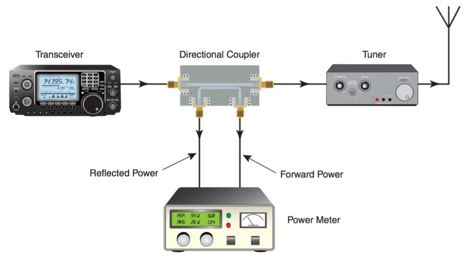
 Whether we are tuning up homebrew equipment, checking antenna VSWR, adjusting a linear amplifier, or just monitoring output power during a contest, almost all aspects of ham operation can use a power meter. Paul Wade W1GHZ
 -
 Based on original G2BCX design this J-Pole antenna for the six meter band is made with a homemade ribbon cable. The antenna shown in this article includes a coaxial cable choke feed to remove RF currents from flowing on the outer of the cable.
 -
 GW4ALG's _136 kHz Pages_ document the evolution of vertical antennas for the 2200m band, starting with a prototype mounted on a house wall. This initial design, despite achieving the first **395 km** GM-GW QSO, suffered from significant insulation breakdown, high RF losses due to proximity to the house, and difficult tuning adjustments. The author details the challenges of maintaining resonance and matching with a variometer in the loft, noting that adding three earth spikes offered no measurable improvement over a simple water tap connection. The subsequent experimental 12m vertical, relocated away from the house, significantly reduced dielectric losses and proved far more effective. This antenna enabled GW4ALG to set a world DX record on 136 kHz with a **1916 km** QSO to OH1TN, and an intra-UK record of **703 km** to GM3YXM/P. The resource further explores the use of helium-filled balloons to extend the vertical radiator, achieving heights up to 27m, typically 20m, for enhanced low-band performance. Practical advice on balloon types, inflation, and critical insulation between the wire and balloon is provided, emphasizing safety and avoiding arcing.
 -
 The Vee Beam antenna project presents a versatile solution for hams, enabling operation across all eight High Frequency bands (80m to 10m) with significant gain on 20m to 10m. This easy-to-construct antenna utilizes two long wires at an angle, enhancing directional performance and minimizing ground losses. With a low visual profile, it is discreet and effective for various applications. The design allows for optimal leg lengths and included angles, ensuring robust performance while maintaining simplicity in construction and operation. The V Beam antenna is an aerial that you can use on all eight High Frequency amateur bands (80, 40, 30, 20, 17, 15, 12 and 10m) with an antenna tuner, and which gives significant gain on the five bands from 20 to 10 meters band.
 -
 The document provides a detailed guide on modifying an inverted-L antenna to include the 160 meters band. This enhancement allows amateur radio operators to utilize the lower frequency effectively, which is crucial for long-distance communication, especially during the night. The inverted-L design is popular due to its compact size and ease of installation, making it suitable for various environments. By adding top band capabilities, operators can engage in DXing and contesting on 160m, expanding their operational range and opportunities. The guide includes practical tips and considerations for construction, ensuring that the antenna maintains its performance across the extended frequency range. It discusses the necessary adjustments and materials required for the modification, along with potential challenges and solutions. Whether you are a seasoned operator or a beginner, this project can enhance your station's capabilities, allowing for more versatile operations and improved signal quality on the 160m band.
 -
 A 500-watt mobile antenna project details the conversion of an old 10m hamstick into a highly efficient, multiband "bugstick" for HF operation. The core modification involves replacing the original coil with 25 turns of 6 turns-per-inch, 1.5-inch diameter coil stock, fabricated from #14 wire. This design, intended for a 3-magnet mount on a vehicle cab, achieves resonance on multiple bands by shorting out specific turns on the coil, similar to a **bugcatcher** antenna. Measurements taken with an MFJ-259 analyzer on a GMC pickup show 0 turns shorted for 20 meters (14.2 MHz), 10 turns for 17 meters, 16 turns for 15 meters, 19 turns for 12 meters, and 23 turns for 10 meters. The construction emphasizes using UV-resistant tie-wraps and #14 solid wire with crimp lugs for robust RF connections, bypassing the fiberglass rod for current flow. A bonus section details a 40-meter version, utilizing 48 turns of 8 TPI, 2-inch diameter coil stock.
 -
 Codec2, an open-source speech codec, targets low bit rate voice communication, specifically designed for digital radio applications operating within constrained bandwidths. The project focuses on achieving intelligible speech quality at data rates around 2400 bits per second, a critical parameter for efficient spectrum utilization in amateur radio. Its development addresses the need for robust voice transmission over channels where higher bit rate codecs would be impractical or inefficient. The resource details the technical specifications and implementation aspects of Codec2, including its underlying algorithms and performance characteristics. It provides insights into how the codec processes speech to achieve its low bit rate, outlining the various coding schemes and their impact on voice fidelity and error resilience. The information presented allows radio amateurs and developers to understand the codec's operational principles and its suitability for integration into custom digital communication systems. Applications for Codec2 extend to digital voice modes on HF and VHF bands, enabling more users to share limited spectrum resources. The project's open-source nature facilitates community contributions and widespread adoption, fostering innovation in digital amateur radio. It represents a significant effort to provide a freely available, high-performance speech coding solution for the amateur radio community.
 -
 Over 1,000 stations in approximately 60 countries were worked using this modified twin-lead folded dipole, demonstrating its effectiveness with just 4 watts on 20 meters. This design, adapted from an ARRL Handbook concept, eliminates the shorting strap found in traditional folded dipoles, simplifying construction while maintaining performance. It utilizes readily available 300-ohm TV antenna feeder ribbon, making it a cost-effective solution for radio amateurs. The antenna's robust construction allows it to handle up to 100 watts without issues, even without a **balun**. The inclusion of a variable trimmer capacitor at the stub provides flexibility for tuning across different frequencies within a band, a practical feature for operators using transceivers like the Icom 735. Formulas are provided to calculate the precise dimensions for any desired operating frequency, enabling customization for various **HF bands**.
 -
 A simple RF power amplifier initially designed for 40 meter band can work on 10 15 20 40 80 meters
 -
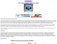
 Every ham needs an RF power meter. Here is a high performance unit to build at home.
 -
 The two linear amplifiers are ment for use with QRP SSB/CW/FM/AM transmitters on the amateur bands 15 and 17 meters can be powered from a 12 volt DC supply by ON6MU
 -
 This document details the design and construction of a Vinecom 6N4 dual-band Yagi antenna for the 50MHz (6-meter) and 70MHz (4-meter) amateur radio bands. The antenna features 9 total elements (4 elements for 50MHz, 5 elements for 70MHz) on a 4.236-meter aluminum boom. Computer simulations using MMANA software predict 7.21 dBd gain on both bands with front-to-back ratios of 16.01dB (6m) and 15.37dB (4m). The design uses 12.7mm diameter elements mounted on a 32mm square boom, weighing 5.7kg total. Practical measurements with an MFJ-269 analyzer confirmed good SWR performance across both bands after element length adjustments.
 -
 The circuit described below will substantially reduce or completely eliminate interference from almost any local source whilst leaving the wanted signal relatively unaffected, even though it may be on the same frequencey by TREVOR, G3ZYY
 -
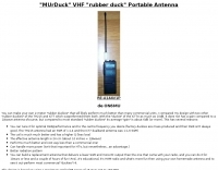 You can make your own 2-meter "rubber duckies" that will likely perform much better than many commercial units.
 -
 The Collins TRC-75 autotune linear amplifier, owned by JF2SVU, is presented with a focus on its internal modifications. This QRO amplifier utilizes three 4CX250 tubes in parallel for its final stage, delivering 1 KW output power. Notably, the amplifier achieves full power with only 100 mW of RF input, a characteristic often associated with Collins designs. The original 400 Hz power supply has been converted for easier shack integration, and the entire RF and power supply sections have been rehoused into a compact, clean enclosure. The control unit, positioned above the amplifier, features three meters for individual vacuum tube IP monitoring and a multi-meter on the right. A dedicated 7 MHz receiver, recently completed, is also part of this integrated system. The autotune functionality means the main amplifier unit only requires connections for power, control, and coaxial cables, simplifying its operation. Key components like the 4CX250 tubes and NF capacitors are visible, along with the gearing mechanism for the final tank circuit. A timer and relay system manages high-voltage delay and cooling fan off-delay, although the cooling fan's airflow is noted as somewhat insufficient. A central volume control, which experienced a contact issue, is also highlighted.
 -
 The G5RV multiband HF antenna, designed by Louis Varney (G5RV) in 1946, is a popular compromise antenna offering good overall performance on most HF bands when paired with an external antenna tuner. The basic full-size G5RV measures 102 feet across the top for 80 through 10 meter operation and is fed at the center via a 34-foot low-loss feed-stub. This interaction between the radiating section and the feed-stub facilitates matching across 80-10 meters with a standard tuner, often eliminating the need for ladder line directly to the shack. The antenna's design center frequency is 14.150 MHz, configured as a 3/2-wave dipole on 20 meters, with its 102-foot length derived from long-wire antenna formulas. Construction details emphasize the matching section, which can be open wire, ladder line (window-type), or TV twin lead. Each type has a specific velocity factor (VF) affecting its physical length for an electrical half-wave on 14 MHz; for instance, open wire requires 33.7 feet (VF 0.97), ladder line 31.3 feet (VF 0.90), and TV twin lead 28.5 feet (VF 0.82). The article provides formulas for calculating these lengths and discusses the antenna's behavior on individual bands, from 3.5 MHz where it acts as a shortened dipole, to 28 MHz where it functions as two three-half-wave long-wire antennas fed in-phase. Practical construction notes include recommendations for vertical descent of the matching section, sealing the coax junction, providing strain relief, and winding a coaxial choke coil to mitigate common mode current. The resource also presents dimensions for double-size (204 ft) and half-size (51 ft) G5RV versions, along with their corresponding matching section lengths for various line types, making it a versatile reference for hams considering this classic wire antenna.
 -
 Accurately determining an antenna's feedpoint impedance is crucial for optimal performance, especially when experimenting with new designs or making adjustments. While SWR meters provide basic information, a full complex impedance measurement reveals the resistive and reactive components, which are essential for proper matching. Modern antenna analyzers, like the _Palstar ZM30_ or MFJ259B, simplify this task, but measurements taken through a transmission line require careful interpretation due to impedance transformation. This resource details a calibration method to precisely account for the effects of the feedline. It explains how a transmission line can significantly alter the measured impedance, illustrating this phenomenon with a Smith Chart example where an 80m antenna's [22 + j6] Ohms feedpoint impedance transforms to [82 + j45] Ohms after a 10m line. The guide demonstrates using a transmission line calculator applet, such as the one by W9CF, to reverse this transformation. It outlines the process of calibrating a specific length of RG174 coax, showing how an initial 26ft estimate was refined to **25.85ft** to accurately predict a known 22 Ohm load, significantly improving accuracy over uncalibrated results.
 -
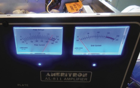 A solutiom for the Ameritron AL-811(H) RF power amplifier, burnt panel meter lights. A common failure with the Ameritron AL-811 and similar amplifiers is that the panel meter lights burn out prematurely. These bulbs are usually integrated into the actual panel meter. The solution for this is to provide the meter backlighting with LEDs.
 -
 RF Power Meter using for reading a standard Digital Voltmeter by Iulian Rosu, YO3DAC / VA3IUL