Search results
Query: 20 m vertical
Links: 162 | Categories: 3
-
 Presents DJ5IL's personal amateur radio station, detailing his journey as a licensed operator since 1973. The resource covers his **shack setup**, including an Elecraft K4D, Icom IC-7610, and various vintage transceivers like the Drake 2-B, along with a SPE Expert 1K-FA amplifier. Antenna systems include a PRO.SIS.TEL RD1524T rotary dipole for 40/20/15/10m at 15m height, an 18m vertical dipole with an SGC SG-230 tuner for 3.5-30 MHz, and an inverted-V dipole for 80m. The site features a **QSL gallery** showcasing his custom card designs and outlines his QSL policy, emphasizing the exchange of unique, personalized cards over generic confirmations. It also includes a detailed operator's biography, tracing his early fascination with radio, obtaining his license at 16, and memorable QSOs, such as a contact with his blood-relative W3NZ. The resource also delves into the historical significance of amateur radio's role in pioneering shortwave communication following the 1912 International Radiotelegraph Convention, which initially relegated amateurs to wavelengths of 200 meters and shorter. DJ5IL's philosophy on "ham spirit" is discussed, stressing the unpolitical nature of amateur radio as a global fraternity.
 -
 The 2m 7 element Yagi antenna is a perfect beam antenna with 11dB gain and a front-to-back ratio of 20-25 dB. It has seven elements and requires a matching network built of 3/8" aluminum tubing and RG-8 cable. The gamma tube is adjusted to provide the best fit, and the gamma-driven element feeding clamp is tightened. If the beam is vertical, a non-conducting mast is utilized to prevent detuning and skewing of the radiation pattern. For optimal VHF operating, the antenna is installed at a height of 30 feet or higher.
 -
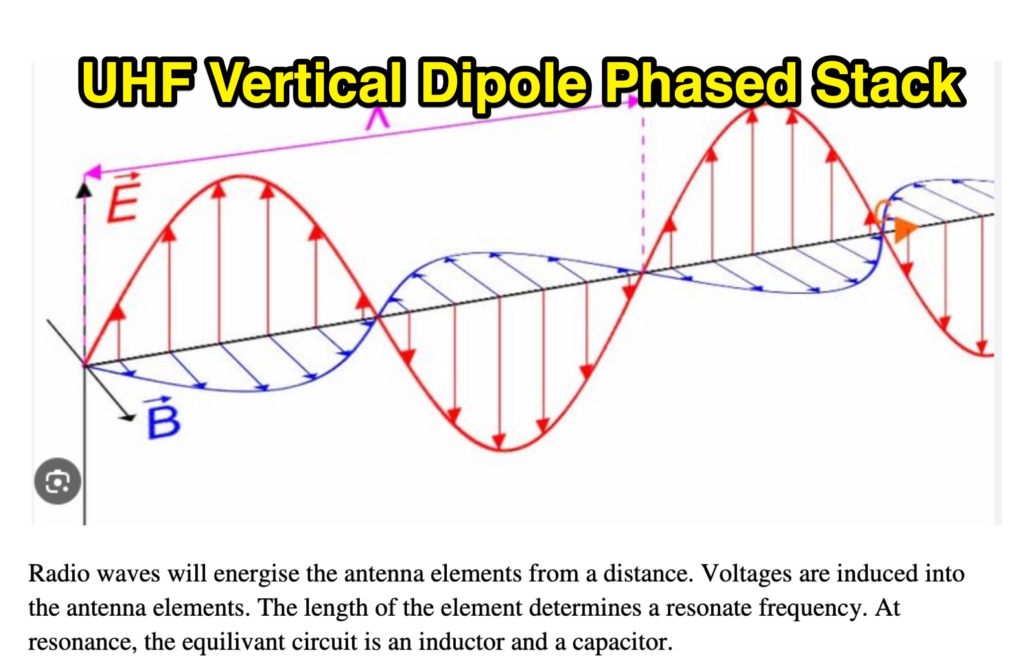 This PDF document discusses the setup and operation of UHF vertical dipole phased stack antennas for hams. It covers the advantages, principles, and practical aspects of using this type of antenna configuration. The document is a useful resource for amateur radio operators looking to improve their UHF station setup with phased array antennas.
 -
 VE1ZAC's analysis details the performance of **MFJ927** and **SGC239** autotuners with portable HF vertical antennas, specifically comparing 31 ft and 43 ft configurations. The resource originated from challenges encountered during a Maritime QSO Party roving operation, necessitating a lightweight and easily deployable antenna system. Target bands for the contest included 80, 40, 20, 15, and 10 meters, with a maximum power handling of 100 W CW. The author utilized a 30-foot carbon fiber push-up pole to support a vertical wire element, noting its 2 lb weight and reliability. EZNEC modeling was employed to predict performance, showing favorable results for a 30-foot vertical with elevated radials, particularly on 40 and 20 meters. Feedpoint impedance measurements, taken with an AIM4170C, are presented for various HF bands, both with and without a 41-foot RG6 stub designed to reduce reactance on 80 and 20 meters. The stub significantly improved matching on these bands, easing the tuner's workload. Operational tests revealed issues with the MFJ927's reliability during contest setup, leading to reliance on the K3's internal tuner. The SGC239, tested post-contest, performed flawlessly. A detailed side-by-side comparison covers mechanical aspects, connection options, power bias, impedance range, board quality, and documentation. Modifications to the MFJ927, including a new aluminum case, white paint for heat reduction, and upgraded impedance-measuring resistors, are also described.
 -
 The TY0RU DXpedition to Benin in 2022 achieved over **100,000 QSOs** from Cotonou, IOTA AF-051, operating across 160m through 6m bands using CW, SSB, and FT8 modes. The operation involved a team of 12 operators, including _F5RAV_, _F4WBN_, and _F1TCV_, utilizing multiple stations with transceivers like the Icom IC-7300 and IC-7610, paired with amplifiers and various antennas such as verticals, dipoles, and a 4-square array for 40m. The expedition's log is available on Club Log, supporting OQRS for both direct and bureau QSLs, with F5RAV serving as the QSL manager. The site details the team's travel, setup, and operational challenges, including local conditions and equipment deployment, offering insights into the logistical complexities of activating a rare DXCC entity. Donors are acknowledged, and a photo gallery documents the activity.
 -
 This project describes a high-performance EME antenna array consisting of two home-designed 9-element Yagis, each about 2.5 wavelengths long, combined into a 25-ohm system and matched to 100 ohms using 9/4λ sections of 50-ohm coax. The array supports rotatable polarity from 0° to 180°, allowing both horizontal and vertical polarization to optimize moonbounce performance under varying conditions. Despite operating for years without a balun—something another designer called “disastrousâ€â€”the system has delivered strong results, including copying very weak DX such as VK3KH at about -25 dB with only 120 W (around 2 kW ERP). The builder continues to refine the mechanics, having installed new gear motors and an upgraded follow-up control system in 2011.
 -
 Details the construction and performance of a phase-controlled receiving array, specifically a **MicroSWA** variant, optimized for QRP low band fox hunting on 40M and 80M. The resource documents the author's iterative design process, addressing significant regional noise challenges encountered during 0100-0230 UTC fox hunt periods. Initial experiments involved a director wire on a 40M vertical, yielding limited improvement, prompting a shift towards advanced null-steering techniques. The project leverages concepts from Victor Misek’s "The Beverage Antenna Handbook" and Dallas Lankford’s extensive work on phased receiving antennas for urban lots. A key modification involved integrating a new passive phase control box and a push-pull **Norton common base preamp** using 2N5109 transistors, designed for high third-order intercept performance to maintain weak signal integrity amidst strong adjacent signals. The system incorporates Faraday-shielded transformers with RG174 primaries on -75 ferrite cores, housed in ABS plastic pipe. Performance tests confirmed the MicroSWA's ability to produce deep, steerable nulls, achieving approximately 30 dB noise reduction on 160M, 80M, and 40M. This enabled detection of QRP signals undetectable on conventional transmit antennas. The final unit includes front panel controls, a 10-11 dB preamp, and a robust power conditioner, demonstrating effective noise mitigation for challenging low band QRP operations.
 -
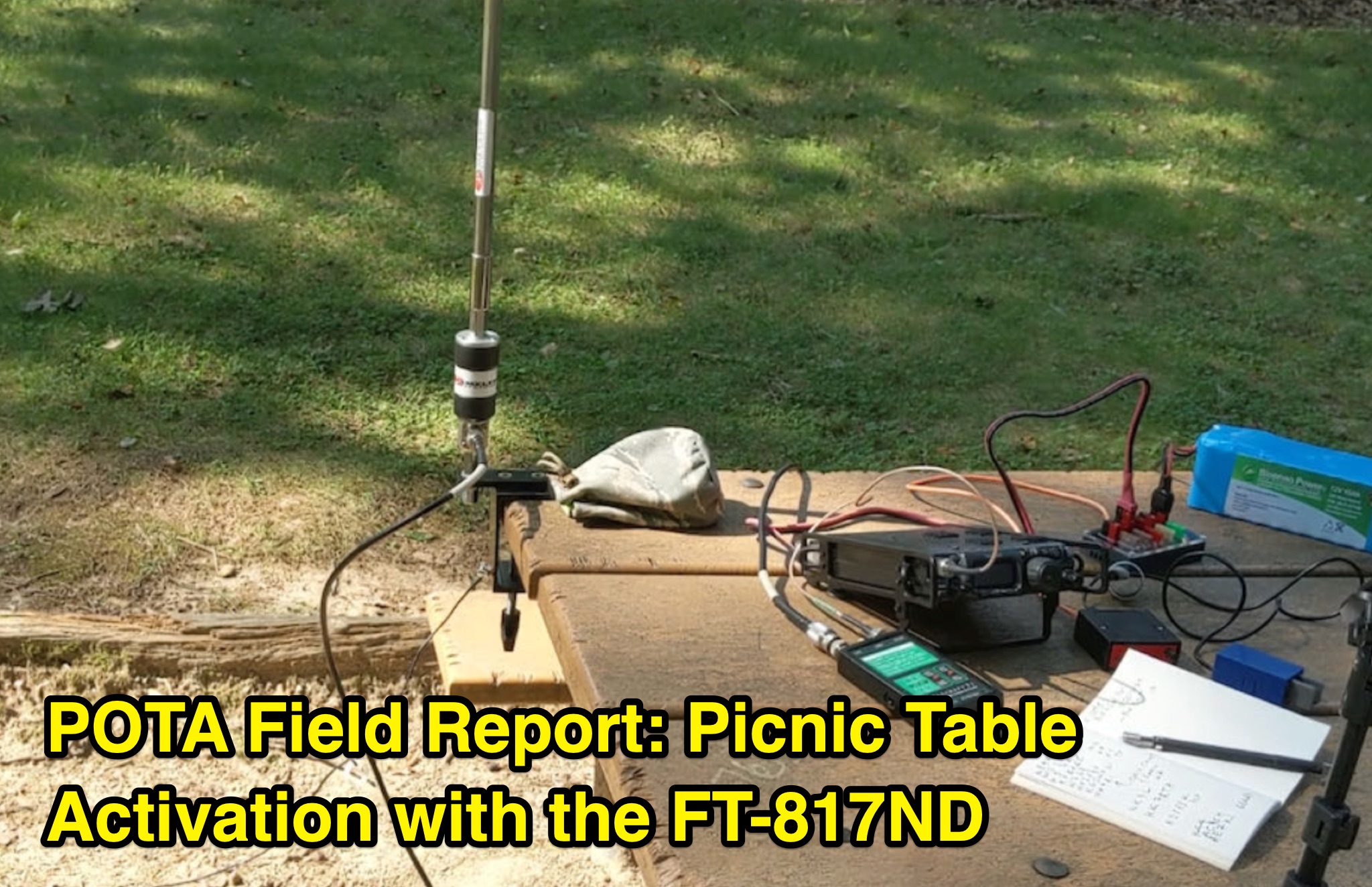 Read about a ham radio operator's experience activating a POTA site at the Folk Art Center using the Chameleon MPAS Lite vertical antenna and the Chameleon Universal Clamp Mount (CHA UCM). Discover how the author carefully deploys antennas to avoid interference with other park visitors and learn about the features of the CHA UCM, a simple antenna clamp mount. Follow along as the author shares their setup and operating spot choices to maximize their portable radio experience while enjoying the peaceful surroundings of the Blue Ridge Parkway.
 -
 The W6PQL 23cm Beacon Project describes a **1296 MHz** beacon designed for microwave propagation studies and equipment testing, capable of 30 watts output. It utilizes a PIC 16F628A microcontroller to generate CW and FSK keying for a crystal oscillator, followed by a series of frequency doublers and triplers to reach the target frequency. The final power amplification stage employs a Mitsubishi M57762 module, providing a robust 10-watt RF output. The design emphasizes stability and reliability for continuous operation, with the microcontroller code, written in assembly, provided for customization of the beacon's callsign and message. Originally located in CM97am and aimed at 140 true, the beacon used four 4-foot Yagis stacked vertically for a total ERP of 3kW. The article includes schematics, parts lists, and construction notes to guide builders, along with antenna pattern measurements. Although the beacon itself is no longer in service as of August 2010, the detailed documentation remains a valuable reference for amateur radio operators interested in building similar **microwave** projects or understanding beacon operation.
 -
 The XW4DX DXpedition website documents the amateur radio operation from Laos, a country ranked #98 on Clublog's Most Wanted list. This resource provides insights into the planning and execution of a significant DXpedition, including antenna choices like _Hexbeams_ at 14m, a 4-square for 40m, and a top-loaded vertical for 160m. The team, comprising operators such as _F4BKV Vincent_ and _F2DX Patrick_, focused on challenging paths, particularly towards the North American East Coast, where Laos is #41 most wanted. Operational constraints included prohibitions on 6m, 30m, 60m, and 80m bands within Laos, necessitating a focus on other HF frequencies, especially 160m and 40m. The expedition utilized up to five stations simultaneously, with equipment transportation being a major logistical challenge, partially mitigated by direct shipments from _Spiderbeam_ and donor support. The expedition ran from November 16th to 27th, 2023, with the complete XW4DX log uploaded to LoTW by December 23rd, 2023. This site serves as a historical record of their efforts to put Laos on the air for DXers worldwide.
 -
 TX5EU 2026 DXpedition to Raivavae Island, **OC-114**, within the Austral Islands, providing a detailed account of the German/Dutch team's operations. The resource outlines the participation of operators such as DL2AWG Guenter, PA2KW Evert, and DK2AMM Ernoe, who engaged in CW, SSB, RTTY, and various digital modes. It documents the real-world challenges encountered, including significant equipment failures and antenna damage to 80/60m, 30m, and 10m verticals due to adverse storm conditions. The page offers timely news updates on the expedition's progress, noting repairs to a power amplifier's 10/12m bandpass filter, which enabled three stations to utilize amplification. Earlier reports highlighted power failures and the loss of multiple power amplifiers, necessitating one station to operate barefoot FT-8 with 100W. The team's persistent efforts to repair antennas as weather permits are also detailed, reflecting the dynamic nature of remote island operations.
 -
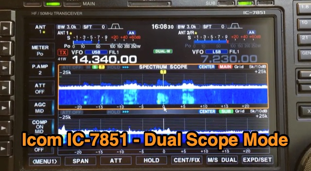 The Icom IC-7851 features the capability to display two scopes simultaneously, providing frequency, mode, and antenna information for each receiver. Users can choose between vertical or horizontal display orientations, and the dual scopes are also viewable on a high-resolution monitor connected to the radio. Additionally, the IC-7851 allows for mouse connectivity, enabling users to click on signals displayed on either scope for quick tuning. A demonstration video is available showcasing this dual scope functionality.