Search results
Query: ft meter
Links: 260 | Categories: 4
-
 Documents the construction of a **VHF/UHF** antenna addition for the Buddipole HF antenna system, leveraging the existing Versa-Tee component. The project details the fabrication of a custom antenna mount from angle aluminum, including specific drilling and tapping for 3/16"-24 bolts, and the creation of radials from Simpson Strong Tie Insulation Supports. It specifies radial lengths for 70 centimeters (6 inches from the center stud) and 2 meters (19 1/4 inches), noting the use of wire nuts for safety. The resource outlines the construction of a mast from 1/2" ID PVC conduit, connected with 3/8"-24 connecting nuts and bolts, mirroring the Buddipole's modular design. It describes the integration of a mobile dual-band antenna with a 3/8"-24 mounting stud and the custom coax setup with BNC and **PL-259** connectors. Field testing with an FT-817ND and a separate dual-band SWR meter confirmed good SWR on both 2 meters and the 440-450 MHz section of 70 centimeters, with positive reception reports during Field Day activities. Further, the article describes the creation of a custom carrying solution, including a 22-inch tripod bag and a fabric roll-up, to emulate the portability of the original Buddipole system.
 -
 Operating the UoSAT-2 (OSCAR-11) satellite, launched in 1984, presents unique challenges due to its age and current eclipse schedule. This resource provides a historical archive of news, telemetry data, and specialized software for decoding its 145.826 MHz FM beacon. It includes tools like _CTERM_ for terminal emulation and capture, and U2TM for processing ASCII telemetry, enabling hams to analyze the satellite's health and performance. The site also offers audio samples of the beacon and S-band signals, along with details on hardware and software decoders. Reception reports are actively solicited for the satellite's intermittent transmissions, which occur for less than an orbit every 21 days during its eclipse period. The site details how to process raw telemetry data, including instructions for skipping initial frames to improve decoding accuracy with U2TM. It also provides software like SATILL for predicting solar eclipses and tools for determining the satellite's spin period from magnetometer or solar array telemetry, offering insights into its operational status despite its advanced age.
 -
 The Kenwood TS-870S HF transceiver features two state-of-the-art 24-bit 20 MIPS DSP chips, providing over 100dB out-of-passband attenuation and CW bandwidth adjustable to 50 Hz. It operates across 160-10 meters with 100 watts output, incorporating digital filtering, a beat canceller, and 100 memory channels. The radio also includes a transmit equalizer, RX antenna input, and a K1 Logic Keyer, enhancing signal processing and operational flexibility for amateur radio operators. Advanced capabilities include IF stage DSP, dual noise reduction, and an auto notch filter, all contributing to superior signal reception and clarity. The TS-870S offers a variable AGC, voice equalizer, and an RS-232C port for computer control, with Windows™ software supplied. Its built-in automatic antenna tuner functions on all bands for both transmit and receive modes, streamlining station setup and operation. Available accessories such as the DRU-3A digital recording unit, SO-2 high stability crystal oscillator, and VS-2 voice synthesizer option further extend the transceiver's utility. The unit requires 13.8 VDC at 20.5 Amps and is supplied with an MC-43S hand microphone, making it a comprehensive station component.
 -
 The program consists of tabbed pages for various antenna and transmission line calculation. You can compute the values for an inverted L network that will allow you to match the 50 ohm output of the radio, or you can compute the necessary length in the units of choice for a 5/8 wave vertical for 10 meter band.
 -
 Fifty-three digital modes, including PSK31, RTTY, and JT65, are explored in this resource, providing detailed descriptions of their underlying technologies and typical use cases. It covers error correction methods like ARQ in PACTOR and FEC in JT65, alongside modulation schemes such as FSK and PSK. The content highlights the evolution of digital communication from traditional TNC-based systems to modern sound card implementations, emphasizing the role of personal computers in advancing these modes. Specific modes like AMTOR, PACTOR, and G-TOR are discussed, noting their baud rates and error correction capabilities. For instance, AMTOR operates at 100 baud, while PACTOR offers 200 baud with Huffman compression. The article also delves into newer modes like MFSK16, which uses 16 tones and continuous Forward Error Correction, and Olivia, capable of decoding signals 10-14 dB below the noise floor. Each mode's bandwidth, speed, and resilience to propagation challenges are examined, such as MT63's 1 KHz bandwidth and 100 WPM rate, or Hellschreiber's 75 Hz bandwidth and 35 WPM text rate. The resource also lists predominant USA HF digital frequencies for bands like 160, 80, and 40 meters, specifying segments for PSK31, RTTY, SSTV, and Packet. It includes links to freeware and shareware sound card software such as Digipan, FLDigi, and MixW, enabling amateurs to experiment with these modes.
 -
 An antenna for 80 meters band for those who does not have enough space to setup a halwave wire dipole that is aprox 130ft or 40 meters. The antenna is an open-wire-fed shortened dipole
 -
 Presents field test results for an **elevated SuperAntenna MP-1** portable antenna, configured on a tripod for HF operations. The resource details the antenna's setup and performance during a portable activation, focusing on its use across the 40-meter, 20-meter, and 17-meter amateur bands. It includes observations on signal reports and operational considerations for this specific portable antenna configuration. The content provides practical insights into deploying the MP-1 antenna in a non-ground-mounted setup, which is often a point of interest for portable and QRP operators. It documents the author's experience with the antenna's tuning and effectiveness for making contacts under real-world conditions, offering a user-perspective review of its capabilities. The article also features photographic evidence of the antenna's deployment, illustrating the tripod mounting and the overall portable station setup.
 -
 The 2200-meter band (135.7-137.8 kHz) presents unique challenges for amateur radio operators due to its narrow 2.1 kHz bandwidth, low signal levels, and high noise. W1TAG explores various transmission modes suited for this demanding environment, highlighting that traditional voice modes like SSB and AM are impractical. Plain old CW serves as the baseline, demonstrating effectiveness across different modes, though signal-to-noise ratio (SNR) significantly limits practical speeds. The article notes that reducing CW speed below 5 WPM can improve copy, especially with computer-aided spectrum analysis software capable of decoding signals too weak for human ear reception. QRSS, or "CW sent slowly enough that speeds are best expressed in seconds per dot," is a key mode for LF work, with examples ranging from 3 seconds/dot to extreme 240 seconds/dot transmissions. _Argo_ by I2PHD is mentioned as a simple program for QRSS, enabling reception of signals like BRO, a Part 15 beacon, at a distance of **1100 miles**. Other modes discussed include Dual Frequency CW (DFCW), which uses frequency shifts to distinguish dots and dashes, and Binary Phase Shift Keying (BPSK), a phase modulation technique employing 0 to 180-degree phase flips. WOLF (Weak-signal Operation on Low Frequency), a specialized BPSK form by KK7KA, encodes 15-character messages into 960-bit packages, taking 96 seconds to transmit, and has demonstrated successful reception over **672 seconds** for a message from a 1-watt beacon. Further modes include PSK, FSK variations like JASON and MSK, and graphical modes such as Hellschreiber and Chirped Hell. The article concludes with a practical chart comparing the time required to send a simple message like "WD2XES FN42CH " across these diverse LF modes, offering valuable insights for operators planning contacts on the low bands.
 -
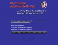 Details the Big Thunder Amateur Radio Club (BTARC), a long-standing amateur radio organization based in Boone County, Illinois, established in 1962. It covers the club's mission to enhance the skills of local hams, promote radio knowledge, and foster social interaction among operators. The resource outlines BTARC's commitment to community service, including emergency communications support through RACES, and its active participation in events like Field Day, fox hunts, and public service communications for local races. Explains the club's history, including the establishment of its first repeater in the 1970s by members WD9JGH, Mike George, K9ORU, and Claude Horsman, WB9PMM, using a VHF Engineering kit and a Sinclair duplexer. It provides specifications for two club-maintained FM repeaters: a 2-meter repeater on 147.375 MHz (+600 KHz shift, 100.0 Hz PL tone) and a 70-cm repeater on 442.825 MHz (+5 MHz shift, 114.8 Hz PL tone). The club hosts a weekly 2-meter net on Sundays at 7:00 PM local time and holds monthly meetings on the second Thursday at the Spring Township Building in Belvidere, IL.
 -
 Amateur radio repeaters extend communication range for mobile and remote stations by retransmitting signals on a different frequency, often for emergency communications. The resource details various repeater bands, noting that 2 meters and 70 cm are primary for activity, with 10-meter repeaters offering potential national and overseas coverage. It specifies **18 channels** on 6 meters and **31 channels** on 2 meters, along with a new 70 cm offset of _7 MHz_ adopted in 2015. The content explains how repeaters can be linked via dedicated transmitters/receivers, landlines, or Internet VoIP systems like _IRLP_ and Echolink, enabling global connections. It also describes simplex gateways for multi-band operation and the use of CTCSS subaudible tones for access control and interference mitigation. The document highlights specialized repeaters for modes beyond voice, such as SSTV and ATV, particularly on 70cm and higher bands. Operational guidelines for efficient and courteous repeater use are referenced, along with links to Australian repeater listings and band plans.
 -
 The MFJ-971 portable antenna tuner, as stock, lacks a bypass switch and sufficient inductance for efficient 1.8 MHz operation. This modification addresses these limitations by integrating a DPDT switch for direct signal bypass, enhancing operational flexibility. Furthermore, the guide details the addition of a T130-2 iron powder toroid, wound with **29 turns** of enamelled copper wire, to augment the tuner's internal inductance. This increases the maximum inductance from approximately 17µH to around **27µH**, enabling effective impedance matching on the _160-meter band_. The modification involves cutting the wire after the 'L' tap on the original inductor and inserting the additional toroid, ensuring the entire original coil plus the new inductance is engaged when 'L' is selected. This preserves the functionality of other inductance settings while extending low-band performance. The article also highlights a potential RF burn hazard from the variable capacitor nuts on the MFJ-971, even at QRP power levels.
 -
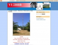 The VU2BBB repeater, located in Matheran, Maharashtra, commenced operations in the late 1980s, a significant undertaking by the Bombay Repeater Society. This repeater facilitates VHF and UHF communications for local amateur radio operators, providing extended range and improved signal reliability across challenging terrain. Its establishment marked a key development in regional amateur radio infrastructure, offering a crucial node for local nets and general QSO traffic. The repeater's operational parameters include specific input and output frequencies within the 2-meter band, typically utilizing a standard offset. CTCSS tones are often employed to mitigate interference and ensure selective access for authorized users, a common practice for repeaters in densely populated areas. Regular maintenance and upgrades ensure _VU2BBB_ remains a reliable asset for the amateur community, supporting emergency communications and daily amateur radio activities. The _Bombay Repeater Society_ continues to oversee its operation, reflecting a sustained commitment to local ham radio services.
 -
 Maintaining vintage Eddystone receivers often presents unique challenges, as detailed by Victor Jenkins in his refurbishment of an EA12, where his deep understanding of RF circuits ensures optimal performance for daily shortwave listening. Similarly, Gerry O’Hara VE7GUH, a prolific contributor to the EUG website and a trustee, meticulously documented his restoration of an Eddystone S830/2, even addressing an unusual instability issue with a follow-up postscript article and YouTube videos demonstrating the fix. His work, along with numerous other articles on the "Restorations" page, showcases a master's approach to bringing vintage sets back to factory specifications or better. Beyond technical restorations, the EUG also shares compelling historical narratives. One such story recounts the discovery of a long-lost 78rpm recording featuring Eddystone Radio Ltd.'s founder, George Stratton Laughton, and other key figures discussing the company's wartime and post-war contributions to shortwave communications. This six-minute BBC production, transcribed into an MP3 file by Peter Carney, offers a rare auditory glimpse into the company's legacy, highlighting its role in supplying equipment to police, ministries, and expatriate British workers. The community aspect thrives through shared experiences, like Roger Trickett's anecdote about his Eddystone EC10, which has been continuously powered for 50 of its 54 years, traveling across continents and enduring various modifications. Another intriguing account from Roy GM4VKI details the "S640 Identity Crisis," where a seemingly standard S640 receiver turned out to be a masterfully engineered 80/20-meter SSB transceiver built into the original chassis by GI3ZX, showcasing incredible ingenuity from a bygone era of amateur radio.
 -
 Presents a historical timeline of amateur radio satellites, beginning with the inaugural _OSCAR 1_ in 1961 and extending through ARISSat-1 in 2011. It outlines the evolution of these orbiting transponders, initially simple battery-operated beacons, into sophisticated platforms supporting educational initiatives, emergency communications, and technology demonstrations. The document highlights the significant contributions of various AMSAT organizations and other entities in developing and deploying these spacecraft. Each entry provides specific launch details, including the date, launch vehicle, and initial orbital parameters such as apogee, perigee, and inclination. For instance, AMSAT-OSCAR 7 (AO-7) launched in 1974 into a 1459.00 x 1440.00 Km orbit, while AMSAT-OSCAR 40 (AO-40) achieved a highly elliptical 58665.00 x 1157.00 Km orbit. The resource also notes the allocated amateur satellite service frequencies, including 29 MHz (10m), 145 MHz (2m), 435 MHz (70cm), 1270 MHz (24cm), and 2400 MHz (13cm). The compilation serves as a concise reference for understanding the progression of amateur satellite technology and operations over five decades, showcasing the collaborative efforts of the global amateur radio community in space communication endeavors. It details the physical characteristics and project affiliations for many of the **20** satellites listed, providing a foundational historical context.
 -
 NFM (for Noise Figure Meter) is a software application to assist Noise Figure measurement. NFM implements the method of Agilent application notes AN 57-1 and AN 57-2 for noise figure measurement, but with the addition of an adjustable attenuator after the noise source and between the DUT and instrument.
 -
 HamGear.eu page about the FT-100, 160 to 6 meter bands plus the 144 MHz and 430 MHz bands transceiver from Yaesu.
 -
 Sixty-meter repeaters typically use a 1 MHz frequency separation between input and output, while 2-meter repeaters commonly employ a **600 kHz** split and 70-centimeter repeaters use a **5 MHz** offset. This article details the fundamental technical principles of amateur voice repeaters, explaining how they extend VHF/UHF communication range by receiving on one frequency and simultaneously retransmitting on another. It covers essential components such as receivers, transmitters, filters, and antennas, often situated on elevated locations for optimal coverage. The resource delves into the critical challenge of _desensing_—where the repeater's strong transmit signal overpowers its own receiver—and the engineering solutions employed, including antenna separation and the use of high-Q cavity filters. It also explores various control and timing systems, from basic squelch activation to more sophisticated microcontroller-based boards that manage functions like voice identification, time-out timers, and fault protection. Different access methods are discussed, including open access, toneburst, CTCSS subtone, and DTMF, each offering distinct advantages for managing repeater usage and mitigating interference. Furthermore, the article examines repeater linking, both conventional RF methods and modern internet-based solutions, highlighting how linking expands coverage and promotes activity across multiple repeaters or bands. It introduces less common repeater types such as 'parrot' repeaters, which use a single frequency and digital voice recording, and linear translators, capable of relaying multiple signals and modes simultaneously across different bands, often found in amateur satellites.
 -
 The original SurplusEQ.com domain, once a hub for amateur radio operators and electronics enthusiasts seeking test equipment, meters, and various high-tech components, has been repurposed. Historically, such platforms facilitated the acquisition of essential gear for shack setups, antenna analysis, and general electronics work, often providing cost-effective alternatives to new retail purchases. The site's previous focus on "test equipment, meters, testers" directly supported the technical aspects of the hobby, from RF measurements to circuit diagnostics. Currently, the domain points to a gambling platform named "SEMUTWIN," offering online slot games, live casino options, and other digital wagering activities. This shift represents a complete departure from its former identity as a resource for surplus electronics and amateur radio-related equipment. The content now features game titles like "Sweet Bonanza Super Scatter" and "Gates of Olympus Super Scatter," alongside promotional offers for online gaming.
 -
 A loop antenna for 80 and 40 meters band, the main loop is based by a crossed line using aluminium strip lines. The main loop diameter is 150 cm.
 -
 The RBN S-Meter visualizes real-time HF propagation data from the Reverse Beacon Network (RBN). It processes thousands of automated spots per hour, providing a real-time picture of active RF paths on HF bands. Users can set their vantage point using _Region Mode_ or _Grid Square Mode_. Region Mode allows selection from broad geographic areas like E. North America or Europe, while Grid Square Mode uses a Maidenhead grid square and radius for more precise data. The app displays eight region panels, each with horizontal bars for bands 160m through 6m, indicating signal strength with a color ramp from green to red. A dimmer trail shows peak hold values, and an S-unit readout provides additional detail. The app is a free web application accessible on any device, offering a practical tool for ham radio operators interested in CW, RTTY, and FT8 signals. It features a Progressive Web App installation option for enhanced usability on mobile and desktop platforms. Users can install it on Android, iOS, and Windows devices, providing a native app-like experience. The app replaces the previous Windows standalone executable, incorporating user feedback to improve features like grid square mode and automatic location detection.
 -
 The ZS1J/B beacon operates on 28.2025 MHz with 5 Watts output to a half-wave, end-fed vertical antenna, initially installed in 1977 as ZS5VHF near Durban. The 10-meter transmitter is a modified 23-channel CB radio, and the identification keyer uses a diode matrix unit with TTL ICs from the same era. After relocation to Plettenberg Bay in 1993, the beacon has been in continuous service, with additional QRP transmitters later installed for other bands. In 1994, a single-transistor, 80-meter, 0.5-watt QRP transmitter with a half-wave dipole was added on 3586 kHz, followed by a 160-meter, 0.5-watt unit on 1817 kHz. A 30-meter, 0.5-watt transmitter was installed in 1996, operating on 10.124 MHz. In 2002, a 40-meter QRRP beacon on 7029 kHz, with an output of 100 microwatts, achieved DX reports up to 1100 km from ZS6UT in Pretoria. Best DX reports for the 80m and 160m beacons came from 9J2BO.
 -
 One of the featured products, the V350 CAMP, is a multiband vertical antenna covering 6 to 80 meters, priced at R$ 799,90, demonstrating the range of ready-to-use solutions available. The inventory includes various antenna types such as **HF**, **VHF**, and **UHF** designs, along with dual-band options like the J-Pole Dual V/UHF for R$ 235,00. For those building their own arrays, the store stocks essential components like element holders, clamps, junction boxes, and aluminum plates, alongside specialized items such as the KIT Isolador Central Dipolo - 01DX for R$ 99,90. The shop also provides a comprehensive selection of installation hardware, including diverse antenna mounts, PTT supports, and various coaxial cables like RG58 and RG213, with prices up to R$ 849,90 for RG213. Connectors such as UHF male PL259 and various adapters are readily available, ensuring compatibility for different setups. Additionally, specialized items like side handles for popular transceivers such as the FT857/891 and IC7300 are offered, catering to specific equipment needs. Beyond antennas, the store supplies practical accessories like transport bags, 12V power cables for transceivers, and even branded merchandise like the Antena Kit mug. Rodrigo Gonçalves, PP5BT, manages the operation from Blumenau, SC, Brazil, providing direct contact via WhatsApp at +55 47 9.9985.0155.
 -
 The W6JWS 2-meter Repeater Maintenance and Repair Log documents the ongoing upkeep of a 146.745 MHz repeater, specifically addressing modifications to enhance its functionality. It details changes made to ensure the repeater powers up in _PL mode_ and to improve the reliability of touch-tone control, drawing comparisons to similar work performed on the AE6KE repeater. The log also notes a repair to a fused wire in the reverse battery protection circuit after an accidental polarity reversal, highlighting a temporary workaround where a wire was omitted but the system remained operational. The resource includes practical insights from Jeff Liebermann, AE6KS, regarding jumper configurations and programming, with accompanying photos. It provides access to several documents for the Icom RP-1510 repeater, including operating manuals and a schematic for the single logic board version, which differs from the dual-board configuration described in some printed manuals. The log mentions a specific modification to adjust the dropout delay, which was later deemed unnecessary, and references a related project for the AE6KE repeater, aiming to replicate successful modifications on the W6JWS machine, resulting in improved touch-tone reliability and proper PL mode activation.
 -
 Over 150 pages of content are dedicated to maximizing activity on the 6-meter band, often referred to as the _Magic Band_. The resource details various propagation modes, including sporadic E, F2, and tropospheric ducting, providing insights into their characteristics and how to leverage them for DX contacts. It also covers essential equipment considerations, from transceivers and transverters to specific antenna designs optimized for 50 MHz operation, such as Yagis and Moxon antennas. The eBook presents strategies for participating in 6-meter contests and pursuing awards like _VUCC_, offering practical advice on logging software and operating techniques. It includes discussions on software tools useful for predicting propagation and managing contacts, alongside guidance on finding and utilizing DX maps to identify openings. The author, K5ND, shares his extensive experience to help operators achieve successful 6-meter DXing. Specific sections address the code of practice for 50 MHz operations and provide assistance in locating rare DX opportunities. The content is structured to guide both new and experienced operators through the nuances of the band, from initial setup to advanced operating strategies.
 -
 Low-frequency (LF) radio time signals, operating primarily in the 40–80 kHz range, are broadcast by national physics laboratories for precise clock synchronization. Transmitters like **JJY** (40 kHz, 50 kW; 60 kHz, 50 kW), RTZ (50 kHz, 10 kW ERP), MSF (60 kHz, 15 kW ERP), WWVB (60 kHz, 50 kW ERP), RBU (66.66 kHz, 10 kW), and DCF77 (77.5 kHz, 50 kW) cover vast geographic areas, often several hundred to thousands of kilometers. LF signals offer distinct propagation advantages over higher-band transmissions such as GPS. Their long wavelengths (3–6 km) enable effective diffraction around obstacles like mountains and buildings. The ionosphere and ground act as a waveguide, eliminating the need for line-of-sight and allowing a single powerful station to cover extensive regions. Ground wave propagation minimizes ionospheric variability effects on transmission delay, and signals penetrate most building walls effectively. Robust and low-cost receivers, often priced at 20–30 USD/EUR, are widely used in radio clocks. These receivers typically comprise a tuned ferrite core antenna, a receiver IC (e.g., Atmel T4227, U4223B, MAS1016) for amplification and AM detection, and a microcontroller for decoding the time signal and phase-locking a local clock. Specific components for DCF77, MSF, and WWVB are readily available from vendors like HKW Elektronik and Ultralink.
 -
 The PG7V Contest Calendar provides a curated listing of significant **HF contests**, with a particular focus on events relevant to European amateur radio operators. It details contest specifics such as start and end times in UTC, eligible bands (e.g., 80 meters, 40 meters, 10 meters), and required exchange information (e.g., serial number, CQ-zone, DOK, locator, age). The calendar includes diverse modes like CW, SSB, PSK63, RTTY, and FT4, catering to various operating preferences. Featured contests include the RSGB 80m Club Championship, WW WPX Contest, IARU Region 1 Fieldday, and ARRL International Digital Contest. Each entry links directly to the official contest rules for detailed information. The calendar also notes specific participation rules, such as the 1 KHz QSY requirement in the HA3NS Memorial Contest or the 24-hour single-operator time limit in the ARRL International Digital Contest. This resource is updated regularly, ensuring timely information for upcoming **contest operations** over a four-week period. It serves as a practical tool for hams planning their contest activity.
 -
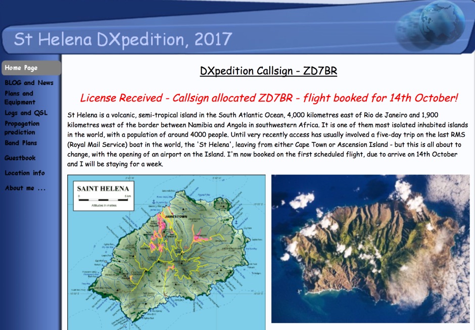 DX Pedition to St Helena 10-80 meters bands SSB RTTY FT8 CW by G0VDE
 -
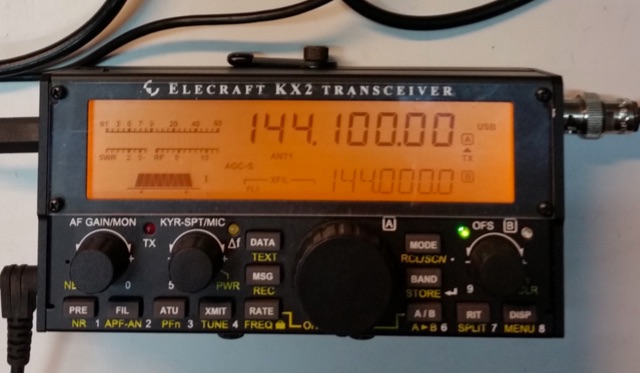 A 144 MHz transverter made by ur3lmz and connected to and Elecraft KX2 transceiver
 -
 A rotary dipole antenna for 30 meters band. Each arm is about 12.5 ft and is constructed from telescoping fibreglass flag/fishing poles and short lengths of aluminium tubing. Two short lengths of glass-fibre rod were used to insulate the arms from the supporting hardware.
 -
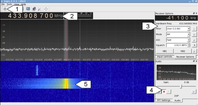 Analyzing 433 MHz radio signals from common wireless devices, such as temperature sensors and remote controls, involves understanding **On-Off Keying (OOK)** modulation. This resource details the process of capturing these signals using a Software Defined Radio (SDR) like Gqrx and then visually inspecting the captured audio data in a sound editor such as Audacity. It differentiates between **Pulse Width Modulation (PWM)** and Pulse Position Modulation (PPM) encoding schemes, illustrating how to identify and decode binary data by eye based on pulse and gap durations. The article provides a step-by-step walkthrough for decoding a wireless thermometer's data, correlating bit patterns with known temperature, humidity, and channel values. It also demonstrates decoding an RF remote control's button presses, highlighting the constant and varying parts of the transmitted packets. The content further introduces automated decoding using tools like RTL_433, explaining its capabilities in parsing various device protocols and showing how to interpret its output, including modulation type and decoded data. Specific examples include analyzing Prologue sensor protocol specifications from RTL_433's source code and noting common operating frequencies like 433.92 MHz in Europe and 915 MHz in the US.
 -
 An Hentenna project for the six meters band. The standard size of standard hentenna is width 1/6 wavelength x height 1/2. The antenna build in this project is a full wavelenght antenna for the 50 MHz providing a 6.8 dbi gain.
 -
 Clarifies the intricate process of calibrating the _Elecraft K2_ dial, addressing common user challenges and lively discussions on the Elecraft reflector. Wilhelm, W3FPR, dissects the K2's PLL synthesizer design, chosen for its low phase noise, kit-friendly duplication, and cost-effective components. The resource emphasizes the critical role of the 4000.000 kHz reference oscillator's accuracy during CAL PLL, CAL FIL, and CAL FCTR functions, noting its dependence on temperature and crystal stability for optimal performance. Explaining the K2's frequency display, the document reveals it relies on microprocessor-driven look-up tables generated by CAL PLL for VFO values and CAL FIL for BFO values. In SSB and RTTY, these combine, while CW and CWr modes also factor in the sidetone pitch. The author details inherent limitations, such as the 10 Hz increment resolution of the dial and varying PLL step sizes—from 3 Hz on 160 meters to 10 Hz on 10 meters. BFO increments range from 20 to 35 Hz, collectively limiting practical dial accuracy to within **20 Hz** with diligent effort, or **30 Hz** for a slightly less demanding task. The guide outlines a four-step calibration procedure: setting the reference oscillator, running CAL PLL, running CAL FIL, and setting all BFOs. It highlights the _N6KR Method_ as a particularly easy and accurate approach, requiring only the K2 and a known frequency source like WWV for zero-beating, eliminating the need for external test equipment.
 -
 This article provides details on building a 6 Meter J-Pole antenna using PVC pipe for an enclosure. This antenna uses flat 450 ohm Window Line for the tuning stub.
 -
 Amateur radio repeaters, often designated by an "R" number like _R6_ or _R5_, serve as crucial infrastructure for extending VHF/UHF communications range. This resource from Essex Ham explains the fundamental concept of a repeater, detailing how it receives on one frequency and simultaneously retransmits on another, typically with a 600 kHz offset for 2-meter repeaters. Understanding the input and output frequencies, along with the required CTCSS tone, is essential for successful access, ensuring your signal is processed and relayed across a wider service area. The article clarifies the importance of using the correct _CTCSS_ (Continuous Tone-Coded Squelch System) tone, often referred to as a sub-audible tone, to activate a specific repeater. It also touches upon the concept of _simplex_ operation versus repeater use, highlighting the benefits of repeaters for mobile and handheld transceivers. Proper operating procedures, such as listening before transmitting and keeping transmissions concise, are emphasized to maintain good amateur practice on shared repeater assets.
 -
 Enables Android users to operate various _miniVNA_ antenna analyzers via Bluetooth, USB, or Wi-Fi, providing a portable solution for RF measurements. The application supports full control over data acquisition, offering features like custom frequency range selection from 1 KHz to the VNA's full range, and automatic screen adaptation for diverse Android device resolutions. It facilitates intuitive, wizard-based calibration for both reflection and transmission modes, saving calibration data for different VNA types (Standard, Pro, Pro with Extender) to avoid repeated procedures. The software displays critical parameters such as SWR, |Z|, Return Loss, Phase, Rs, and |Xs| on 2-axis graphs or Smith charts, with multi-touch gestures for zoom and frequency shift. It includes a frequency generator mode with independent channels and attenuator control for the miniVNA Pro, along with a sweeper function. The cable data mode automatically calculates phase and loss, measures cable length from less than 1 meter to hundreds of meters, and includes a table of common coax cable velocity factors. An experimental X-tal mode measures resonance frequency, Rs, and Q. Data export options include CSV, ZPLOT, and S1P formats, with CSV import capability. The application also features an SM6ENG Audio mode for SWR tuning without visual reference and provides a miniVNA battery voltage indicator. It supports a wide frequency range, with the miniVNA Extender extending coverage up to **1500 MHz**. The application is compatible with Android version 2.2 and later, tested on devices like the _Galaxy TAB 7.7 P6800_.
 -
 Constructing a dual-band antenna for 40 and 20 meters often involves compromises in size or complexity. This resource presents a compact _open sleeve dipole_ design that addresses these challenges by using 450-ohm ladder line and folded elements to achieve a total length of approximately **17.17 meters**, significantly shorter than a full-size 40-meter dipole. The design leverages electromagnetic coupling, where a primary radiator handles the 40-meter band, and a second conductor resonates on 20 meters without direct electrical connection. This configuration eliminates the need for traditional traps, loading coils, or switching components, simplifying construction and reducing potential loss points. The antenna is fed with RG-58C/U coaxial cable, and a common-mode choke is recommended at the feed point to suppress sheath currents, ensuring a cleaner radiation pattern and minimizing RF in the shack. The design is well-suited for portable operations, field deployments, temporary installations, and restricted urban environments where space is a premium, offering solid performance on both HF bands.
 -
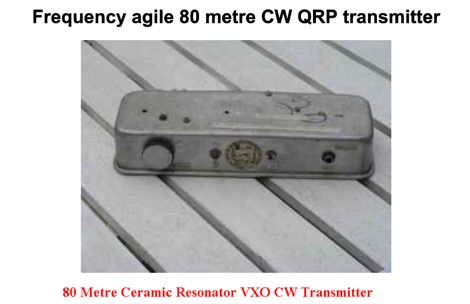 Frequency agile 80 metre CW QRP transmitter. Ceramic resonators vary in the frequency shift obtainable. The one in the prototype of this article gave 3.525 to 3.558 MHz coverage.
 -
 Palau T8GM (OC009) September 6-7 and 15-19 This is solo DXpedition and CW only. Station will be Elecraft K3 and ECO R7+ vertical for 40-10 meters.
 -
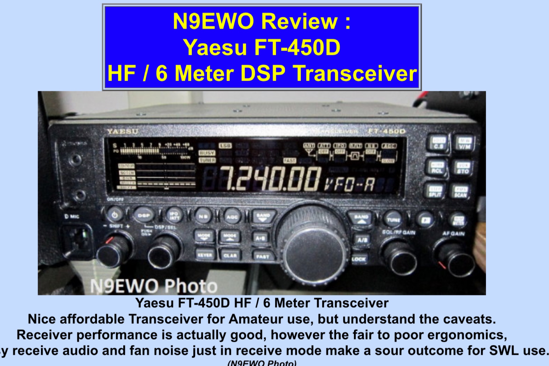 Yaesu FT-450D HF / 6 Meter DSP Transceiver, a nice affordable transceiver for amateur radio use, but understand the caveats.
 -
 Jeri Ellsworthhas started a video series devoted to building a magnetic loop antenna for the 160- and 80-meter bands. The first video, included after the break, is an overview of the rationale behind a magnetic loop
 -
 Operating in antenna-restricted communities presents unique challenges for amateur radio operators, often necessitating creative solutions for antenna deployment. This resource details the design and implementation of stealth antennas within a townhouse community in Exton, PA, where external antennas were strictly forbidden by covenants. The author, WB5NHL, describes his setup, which involved locating the shack in the basement and utilizing an unused space under the roofline of a finished third-floor loft for antenna placement. The content specifically addresses the practicalities of routing coax cables three floors and maximizing antenna performance within limited attic space. It covers solutions for multi-band operation, including dedicated sections for 40-10 meter and 80-meter antennas, along with strategies for mitigating potential interference issues. The approach emphasizes full compliance with community covenants, achieving maximum height-above-ground for horizontal antennas, enabling instant band switching, and efficiently utilizing available attic volume. While acknowledging limitations such as potential interference with high power and fixed antenna patterns, the resource provides a detailed account of a functional compromise for restricted environments. Links to individual pages on _coax cables_, _40-10 meter antennas_, _80-meter antennas_, and _interference issues_ offer deeper dives into each specific aspect of the installation.
 -
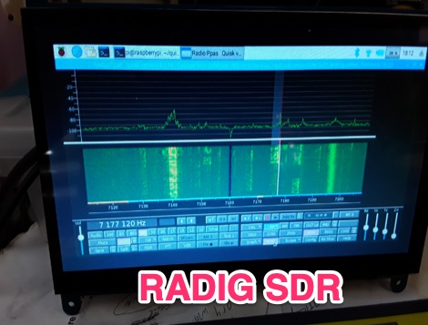 A new SDR radio concept developed by N6QW as an experimental 5W SDR transceiver for the 40 meter bands. Radio and Rig (RADIG) is a term conied by the author.
 -
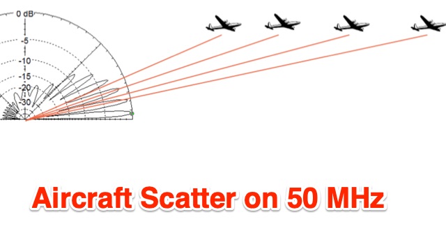 Aircraft scatter is easily seen on the spectrogram window of digital communication apps, when you know what to look for. Examples of real aircraft scatter usage on six meters band
 -
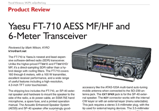 Yaesu FT-710 AESS MF/HF and 6-Meter Transceiver review on QST
 -
 This article provides details on building a 6 Meter J-Pole antenna using PVC pipe for an enclosure.
 -
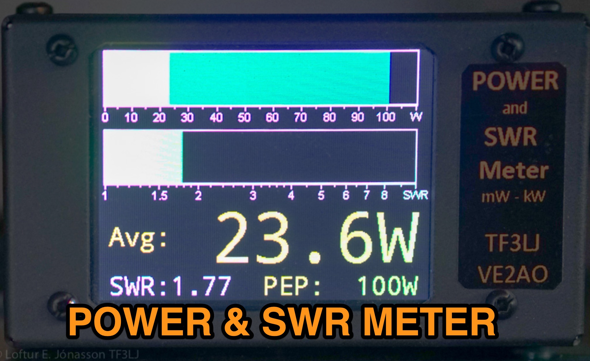 This page describes an update to a project for a Power and SWR Meter for ham radio operators. The update includes a more powerful microcontroller, increased sampling rate, and improved display options. It explains how to use the new components and provides detailed instructions for building the updated meter. The page also offers alternative display options and includes the full source code for the firmware. Overall, this update enhances the functionality and performance of the Power and SWR Meter project, making it more versatile and user-friendly for hams looking to measure RF power and SWR in their radio setups.
 -
 This article explores the evolution of antenna choices for DXpeditions, focusing on the shift from mono-band VDAs to a multi-band solution. It details the design and construction of a lightweight, versatile 20-17-15m VDA, utilizing readily available materials like fishing rods and IKEA breadboards. The author discusses challenges, adjustments, and offers guidance for replication.
 -
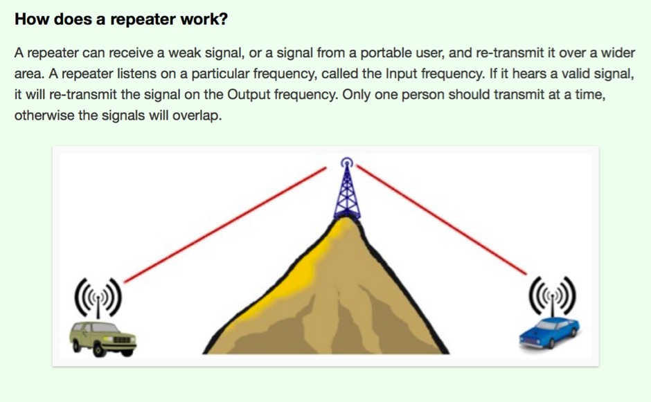
 Explains the fundamental purpose of a repeater, detailing how these automated relay stations overcome distance and terrain limitations for VHF/UHF communications. It traces the historical development from early Bell Telephone Labs "relay" stations in 1922 to Art Gentry, W6MEP's, pioneering K6MYK amateur radio repeater in the mid-1950s, which remains active today. The resource clarifies the distinction between simplex and duplex operation, including the unique function of a "parrot repeater" for single-frequency recording and playback. Delving into the internal workings, the guide breaks down a repeater into its core components: the antenna system, feedline (often _Heliax_ or hardline for minimal loss), duplexer, receiver, transmitter, and controller. It emphasizes the critical role of the duplexer in preventing receiver desensitization by isolating transmit and receive signals, even with distinct frequencies. The discussion highlights the importance of high-performance, durable antennas and low-loss feedlines, citing examples of equipment installed in the 1960s and 1970s that are still in perfect working order. Operating a repeater is also covered, with an explanation of frequency offset (e.g., the 600 kHz standard for 2 meters) and the function of _CTCSS_ (PL tone) for access. It outlines standard input/output offsets for various bands, from 6 meters to 23 centimeters, while noting regional variations. The guide also touches on features like autopatch and Digital Voice Recorders (DVRs), providing a solid foundation for understanding repeater technology and usage.
 -
 The _G3TSO_ Mobile Antenna Page details construction and tuning methods for mobile antennas operating across **10 to 160 metres**. The content describes a Hustler-based design, optimized for RF performance and vehicle speeds, featuring centre loading. For optimal operation on various bands, the loading coil placement requires clearance from the vehicle body. Antenna resonance is critical for efficient mobile operation. A mobile antenna's base impedance may be as low as 27 ohms, requiring specific matching to achieve maximum radiation, as a minimum SWR at the transmitter does not always indicate resonance or maximum output. Tuning involves physical adjustment of antenna length to achieve resonance at the operating frequency. The _G3TSO_ page outlines a tuning procedure utilizing a low-power signal source and a field strength meter to identify maximum radiation before impedance matching. Loading coil placement, either at the base, center, or top of the antenna, influences radiation efficiency and mechanical stability for mobile installations. Centre-loaded whips, such as the Hustler design, offer a compromise between efficiency and stability, often for single-band operation. Helically wound antennas, including those for **28 MHz**, may present base impedances around 17 ohms, resulting in a 3:1 SWR at resonance. Low resistance grounding at the antenna base is also specified for optimizing performance and minimizing RFI during mobile operation. DXZone Focus: Mobile | Any | Antenna Tuning | HF
 -
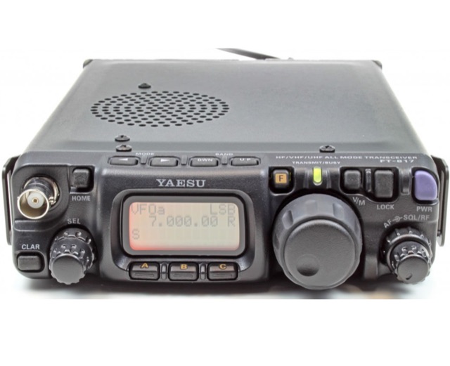 Reflected power and VSWR Metering on Yaesu FT-817, and proper interpretation of real values. The power output meter it is a relative indicator of the antenna match that the radio is experiencing. Reference table and how correctly read the values of the Yaesu internal meter.