Search results
Query: antenna t..
Links: 2506 | Categories: 254
This query is too generic. Please try adding an additional term to focus your research.
Categories
- Antennas > 20M > 20 meter Dipole Antennas
- Antennas > 20M > 20 meter Vertical Antennas
- Antennas > 20M > 20 meter Yagi antennas
- Antennas > 40M > 40 meter Delta Loop Antennas
- Antennas > 40M > 40 meter Dipole Antennas
- Antennas > 40M > 40 meter Loop Antennas
- Antennas > 40M > 40 meter Magnetic Loop Antennas
- Antennas > 40M > 40 meter Vertical Antennas
- Antennas > 40M > 40 meter Yagi Antennas
- Antennas > 6M > 6 meter J-Pole Antenna
- Antennas > 6M > 6 meter Moxon Antennas
- Antennas > 6M > 6 meter Yagi Antennas
- Manufacturers > Antennas > HF > Active antennas
- Software > Antenna analysis
- Manufacturers > Antenna Analyzers
- Radio Equipment > Antenna Analyzers
- Antennas > Antenna Books
- Antennas > Antenna Calculators
- Antennas > Theory > Antenna Gain
- Technical Reference > Antenna Launcher
- Manufacturers > Antenna Launcher
- Manufacturers > Antenna Masts and Mounts
- Shopping and Services > Antenna Mount
- Manufacturers > Antenna Parts
- Shopping and Services > Antenna Parts
- Technical Reference > Antenna Rotator
- Manufacturers > Antenna Rotators
- Software > Antenna rotor control
- Technical Reference > Antenna Switch
- Manufacturers > Antenna Switches
-
 A comprehensive overview of a 10-band attic antenna system developed for contesting and DXing is presented, covering its evolution and performance. Initially intended in a restricted location, the system has been developed through numerous iterations, using various antenna types such as delta loops and Yagis. Automatic switching, dual-direction capability, and optimum tuning for certain band segments are among the most notable features. The project not only improves operating efficiency but also provides great learning opportunities in antenna design and installation in restricted places.
 -
 This article clarifies the roles of baluns, ununs, common mode chokes, line isolators, and impedance transformers in amateur radio. A balun decouples balanced antennas from unbalanced feed lines, preventing interference. Ununs serve a similar purpose for asymmetrical antennas. Common mode chokes and line isolators suppress common mode currents, reducing noise. Impedance transformers adjust antenna impedance to match feed lines but do not decouple or suppress common mode currents. Understanding these components is crucial for optimizing antenna performance and minimizing interference.
 -
 WB8LZR details the construction and initial field results of a multi-band vertical wire antenna, designed to complement his existing horizontal loop for improved DX on 80 meters. The antenna utilizes a 67-foot vertical wire, configured as a quarter-wave radiator on 80m, and employs a 1:1 current balun for RF isolation on 80m, 30m, and 17m. For bands like 40m, 20m, and 10m, where the wire acts as a half-wave or full-wave radiator, an additional impedance transforming _unun_ is integrated to manage the significantly higher feedpoint impedance and voltage. The author notes the vertical's performance as a receiving antenna, observing reduced noise compared to his main horizontal loop, particularly on 80m, and even hearing some long-path signals the loop missed. Initial QRP contacts, including a **1-watt** QSO with a _VP2 station_ on 30m, demonstrate its transmit capability. While the radial system is currently rudimentary, the project outlines practical considerations for multi-band vertical deployment and impedance matching.
 -
 Learn how to easily improve your handheld VHF performance on the 2-meter band with the Flowerpot antenna. This simple DIY antenna made from coaxial cable requires minimal tools and materials, providing a big range upgrade compared to standard rubber-duck antennas. Discover how to build, tune, and optimize the Flowerpot antenna for excellent performance. Ideal for hams looking for lightweight, portable solutions for handhelds, mobile rigs, home stations, SOTA/POTA activations, and emergency communication.
 -
 Presents two distinct hardware modifications for the Icom IC-7300 transceiver, detailing the necessary steps for each. The first modification, a _MARS_ transmit expansion, involves the physical removal of specific surface-mount diodes (D422) from the main board, enabling transmit capabilities across a broader frequency range, including out-of-band frequencies. It specifies the diode location on US versions of the IC-7300 and suggests using small diagonal cutters if a soldering iron is not preferred or available. The second modification focuses on the internal antenna tuner, aiming to provide wider impedance matching capabilities. This involves adding a **100k ohm** resistor to a designated point within the tuner circuit. The resource also briefly mentions a microphone modification for the _HM219_ and a general power increase, though without specific instructions for the latter two. It emphasizes safety precautions, such as disconnecting power and inspecting the work area.
 -
 A 14.12 dBi gain three elements cubical quad antenna for the six meters band. This Quad Antenna design page include a MMA model available to download and dimensions for each element.
 -
 This tutorial provides detailed instructions for constructing a DIY magnetic loop antenna, ideal for amateur radio operators seeking efficient short wave communication. The design features a remote tuning system utilizing an Arduino and RC servo, making it suitable for indoor use where larger antennas cannot be installed. Magnetic loop antennas are compact and can operate effectively in confined spaces, but they do require careful handling due to the high voltages and currents they generate during operation. Users should possess the necessary technical skills to implement this project safely. The tutorial includes a comprehensive overview of the antenna's theory, specifications, and mechanical design. It outlines the components needed, including a Soviet-made variable capacitor and a digital RC servo for tuning. Safety precautions are emphasized, as the antenna can produce several kilovolts of voltage and high currents. The project is not certified for safety, and users are advised to proceed at their own risk. The tutorial also provides diagrams and explanations of the antenna's operation, making it a valuable resource for both beginners and experienced operators looking to enhance their setup.
 -
 In this article the author describes his personal experience on some antennas for 50 MHz he tested on the field, the six meter Dipole, Vertical, Moxon, a 3 element Yagi and an Omniangle antenna.
 -
 This article presents the C-Pole antenna project, a compact, ground-independent vertical antenna designed for amateur radio operators. It features a folded half-wave dipole configuration that eliminates the need for radials, making it suitable for various locations, especially in deed-restricted areas. The C-Pole offers efficient performance with a 2:1 SWR bandwidth of approximately 3%, and it can be easily constructed using common materials. Additionally, the article discusses practical aspects such as feed-point impedance transformation and balun design to optimize functionality and minimize losses.
 -
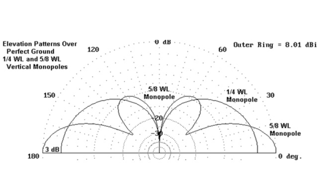 This article on basic antenna theory explains why is a 5/8 wavelength vertical antenna better than a 1/4 wavelength antenna
 -
 This is a design based on the QuickYagi 4 software by WA7RAI with some changes for practical reasons. The beam uses 6.5 metres of standard 25mm square boom, 12mm diameter elements without tapers. The actual boom length used is 6.3 metres and all parts are readily available.
 -
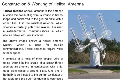 Helical antenna or helix antenna is the antenna in which the conducting wire is wound in helical shape and connected to the ground plate with a feeder line. It is the simplest antenna, which provides circularly polarized waves.
 -
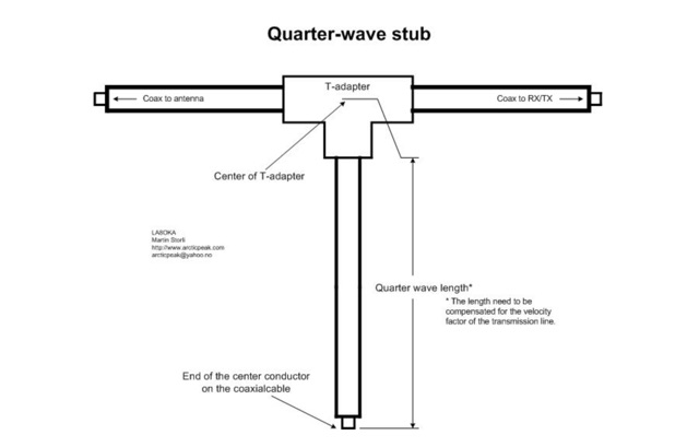 The Quarter-wave stub can be used for many purposes. If it is left with an open end it can be used as a notch filter to attenuate certain frequencies. A quarter wave length of a transmission line can also be used as an impedance transformer, to know more about the Quarter-wave impedance transformer
 -
 Constructing a 5-element quad antenna, the author aimed for low cost and simplicity, resulting in an effective design with 11 dBi gain and SWR of 2:1 or better across the 2-meter band. Using wood and dowels, the antenna costs under $8 and takes less than two hours to build with basic tools. The model predicts excellent performance, confirmed by ARRL Lab measurements. Practical field results demonstrate improved communication, even in simplex mode.
 -
 An homebrew HF Magnetic loop made with 2m length of 6mm diameter copper pipe formed into a near circle as the low loss inductor, a short length of coax as a capacitor,a short length of mains cable, again as a fixed tuned capacitor, a tunable 365pF air spaced capacitor, and a small Jackson C804 airspaced variable with a small 3-35pF trimmer in parallel
 -
 A rotatable 40-meter dipole antenna designed and constructed to fit within backyard constraints. The project utilized two fishing poles attached to a fiberglass center pole, resulting in an easy-to-build, lightweight, and cost-effective antenna. Essential materials included fishing rods, a center support pole, mast support, and basic tools. Linear loading was implemented to achieve the necessary length for optimal performance. The antenna, which proved effective during the contest, is ideal for field days and additional contest bands. Assembly and installation were straightforward, showcasing the antenna's practicality and efficiency.
 -
 This article describes the phases for the construction of a Yagi antenna. The calculations of the parameters are made using 4NEC2 software. This type of antenna is used for transmissions and receptions of electromagnetic waves. The project shown here refers to the frequency of 433.92 MHz.
 -
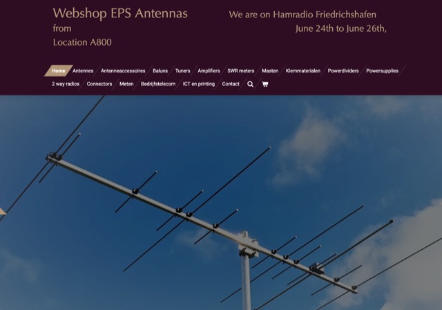 Amateur radio antenna manufacturer, HF VHF UHF antennas, and amateur radio accessories dealer based in Lingen Germany
 -
 Signal Stuff operates as an online retail outlet specializing in amateur radio antennas and related accessories, with a core mission to financially support educational platforms like HamStudy.org and ExamTools.org. The product line prominently features their Super-Elastic Signal Stick™ antennas, available with SMA-F, SMA-M, and BNC connectors, designed for various handheld transceivers including Baofeng, Icom, Yaesu, and Kenwood models. The site details product specifications, pricing, and a lifetime warranty for the Signal Stick™ antennas, emphasizing their role in funding free ham radio licensing study guides and exam administration software. Proceeds from antenna sales directly contribute to the development and maintenance of HamStudy.org, a free online resource for amateur radio license preparation, and ExamTools.org, software utilized by Volunteer Examiner (VE) teams for efficient exam administration. The site also promotes HamBook.org, a free series of comprehensive study guides, which integrates with the HamStudy app and website through links and QR codes for an adaptive learning experience. This business model links product sales to community support, providing essential tools for aspiring and upgrading amateur radio operators.
 -
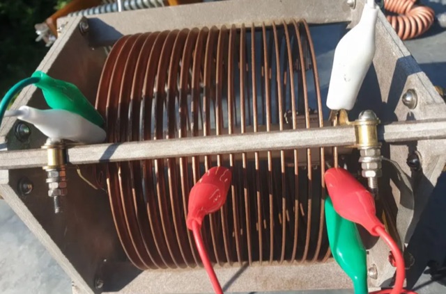
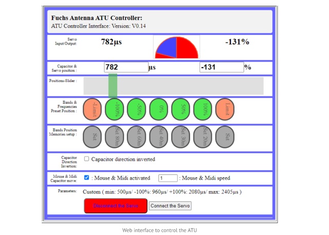 The Fuchs Antenna tuner with a resonant circuit as a coupler. The Fuch Antenna Tuner is providing a high-efficiency compare to a 49:1 transformer using ferrite . The Fuchs tuner is a resonating L/C circuit to step-up the impedance from 50 Ohm to the required 3k. The ATU is able to perform automatic tuning with the addition of a tiny Aduino Nano and a SWR bridge.
 -
 A transmitting antenna 2x15m, about 100 foot doublet antenna fed by a ladder line of about 600 Ohm. Article in Polish and English,
 -
 This document provides a detailed guide on constructing and mounting a folded dipol for the 146 MHz frequency in a vertical configuration to be used in Yagi antennas. The step-by-step instructions and diagrams included make it easy for hams to build and set up this type of antenna. Understanding and implementing this design can enhance the performance of radio communication for Amateurs operating in the 2-meter band. Whether you are looking to improve your signal strength or experiment with antenna designs, this resource offers valuable insights and practical information.
 -
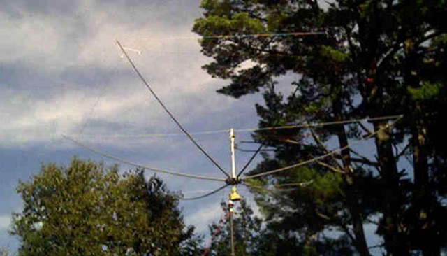
 Low Cost Satellite Antennas article was originally presented at a Project OSCAR seminar on September 30th, 1990. AMSAT-UK printed an abridged version of this presentation in their OSCAR News, Number 88, April 1991. The original presentation has been reedited and updated for AMSAT's Web page.
 -
 This project focuses on testing and comparing various antennas for receiving ADS-B (Automatic Dependent Surveillance-Broadcast) signals, utilizing software tools like RTL1090 and Virtual Radar with an RTL-SDR dongle. The goal is to evaluate the reception range ("ReceiverRange") and performance of different antenna types when tracking aircraft signals, particularly around the Amersfoort area. The project includes a comprehensive photo album documenting the antenna designs and setup processes, serving as a valuable resource for enthusiasts building ADS-B reception systems
 -
 A Magnetic Loop Controller project details the construction and operation of an automatic tuning system for magnetic loop antennas, which are resonant circuits using an oversized inductor and an adjustable capacitor. The system employs a stepper motor to precisely adjust the variable capacitor, maintaining optimal resonance across the HF bands. It integrates with various transceivers, including _Icom_, _Kenwood_, and _Yaesu_ models, by monitoring the VFO frequency and adjusting the loop's tuning accordingly. The project provides comprehensive building instructions, a PowerPoint-style presentation, and the full source code for the controller's firmware, enabling hams to replicate and customize the design. The controller's firmware offers diverse functionality, including automatic frequency tracking, manual tuning, and SWR monitoring, significantly enhancing the operational efficiency of magnetic loop antennas, particularly for QRP and portable operations. The design emphasizes accurate capacitor positioning, crucial for achieving low SWR and maximum radiated power. Comparisons with manual tuning methods highlight the benefits of real-time adjustment, especially when operating across different bands or making frequent QSYs. The project's detailed documentation and available source code facilitate experimentation and modification by advanced builders, allowing for tailored performance characteristics.
 -
 The article describes the construction of a 1:49 impedance transformer designed to match the high impedance (around 2500Ω) of an end-fed half-wave (EFHW) dipole antenna to the 50Ω impedance of a typical transceiver. The EFHW is a popular portable antenna due to its simple construction, but feeding it can be challenging compared to a center-fed dipole. The transformer was built using an FT240-43 ferrite toroid core, with 2 primary and 14 secondary windings for a 1:49 impedance ratio. A capacitor was added in series with the primary winding to improve performance at higher frequencies. The author compared versions with one and two cores, and found that 100pF worked best for the single core design while 200pF was optimal for the dual core transformer.
 -
 The J-pole antenna calculator helps users design custom J-pole antennas for specific frequency bands. It provides dimensions for key antenna sections based on the chosen frequency and material’s velocity factor. The calculator also offers insights into J-pole antenna mechanics, velocity factors, and mounting tips, making it ideal for enthusiasts creating antennas for amateur or mobile radio communications.
 -
 Online antenna calculator for a basic 3 elements yagi uda directional antenna. The described antenna design offers a front-to-back ratio of at least 20 dB, a gain exceeding 7.3 dBi, and a bandwidth (SWR < 2) of approximately 7% around the center frequency. It has an input impedance of 50 ohms when using a straight split dipole, which can be substituted with a folded dipole of the same length, increasing the impedance to 200 ohms. A matching balun is required for coaxial feeder connection, and the boom should be made of a dielectric material, like wood.
 -
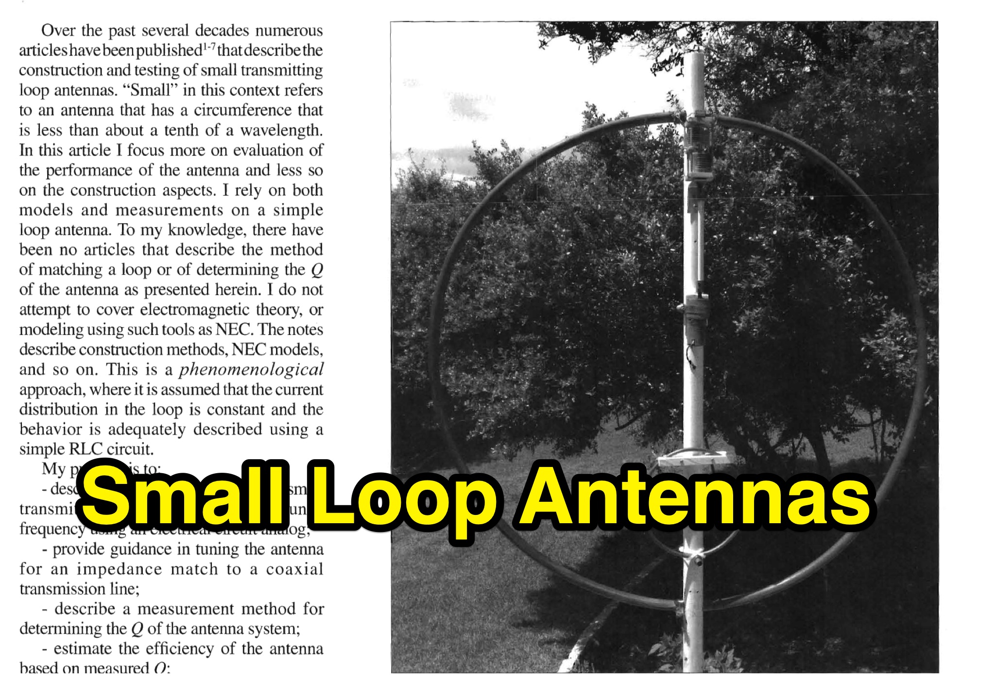 This PDF document provides detailed information on small loop antennas for hams. It covers the design, construction, and usage of small loop antennas for amateur radio operators. The guide includes practical tips and recommendations for optimizing the performance of small loop antennas in various operating conditions. Whether you are a beginner or an experienced ham radio operator looking to improve your antenna setup, this guide has valuable insights to offer.
 -
 This article explores the conventional wisdom about antenna height in amateur radio operations, challenging the common belief that "higher is always better." Through practical examples and computer modeling, it examines how low-height antennas like Beverage antennas, VP2E, and End-Fed Half Wave (EFHW) configurations can perform effectively in various scenarios. The analysis includes radiation patterns and efficiency considerations for antennas at different heights, particularly focusing on portable operations. The article demonstrates that while height affects antenna performance, lower installations can still provide practical and efficient solutions for specific applications, especially in portable and QRP operations.
 -
 The document details the construction and performance of a rotatable flag antenna designed for a small lot. The 7x14 feet flag, built with fiberglass poles and an aluminum hub, shows improved reception compared to the author's previous transmit antenna. Key components include a conventional transformer for impedance matching and a variable resistance termination system to optimize performance. Despite challenges like nearby objects affecting signal patterns, the antenna consistently provides better signal-to-noise ratios, making it a valuable addition for low-band listening in suburban areas.
 -
 A Beverage antenna system consisting of 4 time reversible Beverage antennas in length of 320m each.
 -
 This study details a reception comparison between vertical and horizontal active loop antennas, specifically two identical _Wellgood active loop antennas_, on various HF bands. The experiment, conducted in a densely populated QRM-prone area, monitored FT8 signals over a 24-hour period using two identical receivers. The methodology involved direct comparison of signal reception across the HF spectrum, aiming to identify performance differences based on antenna orientation. The results indicate that vertical loops demonstrated superior performance on higher bands (10m, 15m, 20m), while horizontal loops excelled on lower bands (30m, 40m, 160m), particularly for receiving long-distance (DX) signals. The horizontal loop's advantage on lower bands is attributed to potentially better low-angle performance and reduced sensitivity to man-made noise, yielding a **2-3 S-unit** improvement on 160m. The study provides practical insights for optimizing antenna placement in challenging urban environments, noting that the horizontal loop consistently showed a **10-15 dB** signal-to-noise ratio improvement on lower bands.
 -
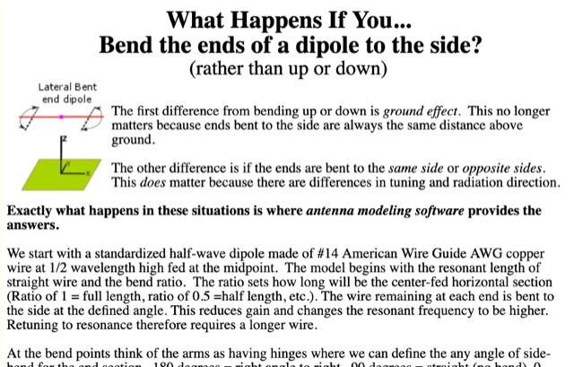 Discussion about laterally bent-end dipoles. Bent by percentage of length and fine-tuned by angling the bent ends.
 -
 A selection of technical articles and analysis offering guidance and insight to enable you to recognise and build your own high performance yagi design.
 -
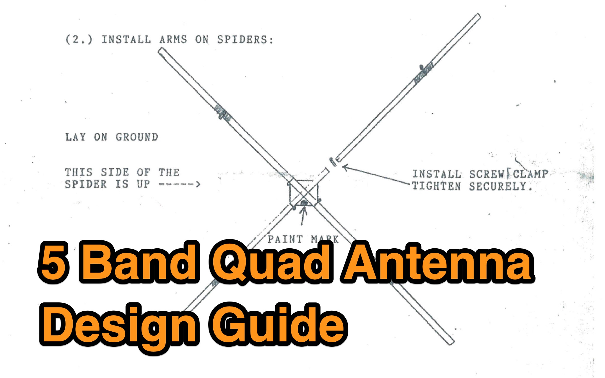 This guide provides detailed information on designing a 5 Band Quad Antenna for ham radio operators. It covers the necessary materials, dimensions, and construction steps required to build the antenna. The guide aims to help hams optimize their antenna setup for maximum performance on five different bands. Whether you are a beginner or an experienced operator, this resource can assist you in creating an effective antenna system for your station.
 -
 This innovative antenna tuning unit (ATU) enables QRP operators to match their antennas without transmitting RF signals. Using a noise bridge technique instead of traditional transmit-and-tune methods, it achieves truly silent operation. The design incorporates an L-match network with switched inductors and variable capacitor, handling impedance matching from 3-30MHz. Operating from a 9V battery, it includes a built-in RF power meter and dummy load for QRP transmitter testing. The compact unit is particularly suitable for portable operations where minimal RF emissions during tuning are desired.
 -
 This project explores the construction and performance of an Alford Loop antenna as an alternative to a round loop. The Alford Loop, symmetrically fed at opposite corners, behaves like a small loop despite its larger size. Built using PVC pipes and secured with tire wraps, the antenna integrates an LZ1AQ active amplifier for optimal performance. With deep nulls in its horizontal radiation pattern and improved resonance characteristics, this design has significantly outperformed previous active antennas in reception quality.
 -
 This project documents the construction and enhancement of a 30m Vertical Dipole Array (VDA) antenna inspired by Remco 7QNL article. Initial design utilized an 18m Spiderbeam pole and a 4m boom. Improvements included a lighter boom structure using fishing rods and a revised coaxial arrangement for enhanced mechanical stability.
 -
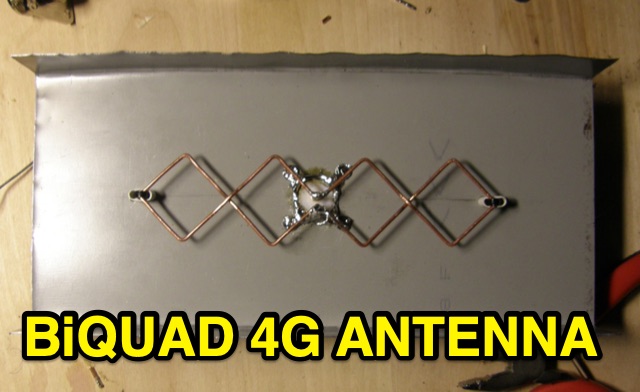 This is basic instructions for homemade 4G Antenna working on 2600 MHz UMTS featuring 13 14 dBi gain. This antenna is desigend to resonate on microwave frequencies in two segments from 2500 to 2570 MHz for Uplink, and from 2620 to 2690 MHz for Downlink.
 -
 Being frequently away from home, the author owner of an Elecraft KX3 missed the opportunity to work /M. They devised a portable antenna solution, incorporating a coil and car body, enabling multi-band tuning. Despite its unconventional design, the antenna exhibits promising performance, resembling a vertical dipole.
 -
 This project details the construction of a compact, circularly polarized Quadrifilar Helix Antenna (QHA) designed for 146 MHz operation. The antenna features a 1/2λ1/2λ helical design with a 2.6:1 aspect ratio, providing 4.5 dB gain and a spheroid radiation pattern. It is ground plane independent and compatible with both vertical and horizontal polarizations, making it ideal for terrestrial and space communications. The design includes step-by-step instructions for building the antenna using readily available materials like aluminum rods, PVC pipes, and RG-58 coaxial cable. The antenna's performance has been validated through comparisons with commercial omnidirectional antennas, showing superior results.
 -
 The article describes the construction of a Lindenblad antenna, which is well-suited for receiving signals from low-orbiting weather satellites. The key points are: The Lindenblad antenna has an omnidirectional horizontal radiation pattern and is optimized for low to medium elevation angles, making it ideal for tracking passing satellites near the horizon. It is designed to receive circular polarization, which is common for weather satellite signals. The antenna is constructed using 4 folded dipole elements arranged on a cross-shaped frame. The necessary materials include a plastic junction box, PVC tubing, and aluminum rods to form the dipole elements. The article provides detailed instructions for preparing the components, assembling the dipoles, and connecting the feed lines to create the complete antenna. The completed antenna can be mounted on a vertical support, with the dipole elements angled at 30 degrees from horizontal, to optimize reception of the passing satellites. The author notes that the design was originally published in a now-defunct magazine, Meteo Satellite Inf", in 1993
 -
 The Hex Beam page by W1GQL page, a document dedicated to home brewing hex beam antenna with dimensions, info on spreaders, wires to use, spacing tips, feed line information, mast to use, multi-band version and antenna height
 -
 This Satellite Antenna Elevation System project involves mounting horizontally polarized Yagi antennas on a fiberglass reinforced polymer (FRP) crossboom. A Yaesu G-800DXA azimuth rotator is in place, requiring only an elevation rotation system. Elevation is controlled by a 12VDC linear actuator connected to a U-bolted arm on the crossboom, rotating within a DIY bearing arrangement. Common handyman tools suffice for assembly. The setup includes FRP crossboom, aluminum tubing, PVC couplers, nylon camshaft bushes, and a K3NG-based controller for azimuth and elevation control. Detailed guides and resources are available online.
 -
 Initially planned as an article on the R-407 station mast, this project evolved into creating a custom mast kit. Utilizing original materials, the design was modified for cost-effectiveness and practicality in home assembly. The new mast extends to 10 meters, featuring secure connections, a leather-lined base to prevent metal-on-metal friction, and sturdy military-grade anchors. Modifications include lengthened connecting tubes, improved anti-rotation features, and a convenient base design for solo assembly. Ideal for amateur radio operators, this mast provides stability, ease of construction, and versatility, proving more economical than professional products without compromising on performance or reliability. Article in Czeck.
 -
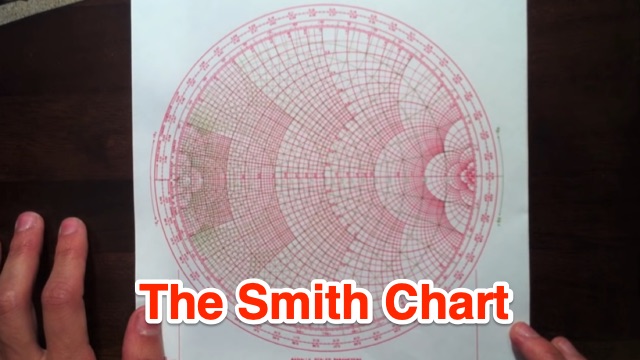 This tutorial introduces and explains Smith Charts, and then gives an introduction to impedance matching. Smith Chart is a tool to visualize the impedance of a transmission line and antenna system as a function of frequency.
 -
 A homemade quarter wave ground plane anntenna for 4 meters band.
 -
 The article details the C-Pole antenna project, emphasizing its portability and ease of setup for amateur radio operators. Key features include its compact design as a vertical half-wave dipole that requires no radials, making it functional at various locations. The antenna employs capacitive loading to reduce physical length while maintaining efficiency. It includes practical advice on resonance tuning, impedance matching, and construction materials, along with a calculator for determining dimensions based on desired frequencies. Overall, it presents a user-friendly solution for portable ham radio communication.
 -
 IAT is an excel sheet table evaluate parameters of VHF UHF antennas edited by Vladimir UR5EAZ. The difference between this tool and the existing VE7BQH Antenna Table is the use of G / T and C / N instead of the G / Ta parameter. In this table, Vladimir applies the ITU recommendations to assess the noise properties of a radio receiving system and shows the advantage of the G / T concept over the G / Ta concept when choosing an antenna.