Search results
Query: 2 elem
Links: 572 | Categories: 5
-
 6 element super duper moxon antenna for the 144 MHz, a modified HAARP Antenna projetc
 -
-
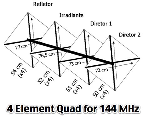 A project for a four element cubical quad antenna for 144 MHz in portuguese
 -
 OpenTracker+ and Tracker2 series APRS devices for real-time vehicle tracking, weather monitoring, and remote telemetry, aprs tracker manufacturer.
 -
 Operating a ZS6BKW antenna often involves understanding its lineage from the _G5RV_ design, with specific modifications by ZS6BKW to optimize performance on several bands. Through computational analysis and field measurements, the antenna's dimensions were refined to allow operation on 10, 12, 17, 20, and 40 meters without an antenna tuner. For 80, 30, and 15 meters, a tuner is necessary, though efficiency on 30 and 15 meters is noted as not particularly high. The physical configuration consists of two 13.755-meter radiating elements fed by a 12.20-meter section of 450-ohm ladder line. Tuning the antenna on the 20-meter band is critical, and any deviation in the ladder line's characteristic impedance necessitates recalculating the element lengths. The design is also referenced in the 12th edition of _Rothammel's Antennenbuch_, page 219. Proper common mode current suppression is crucial at the transition from ladder line to coaxial cable. This can be achieved with a common mode choke, such as several turns of coax wound into a coil or over a ferrite toroid like an Amidon T130. While a 1:1 balun is an option, it may introduce issues.
 -
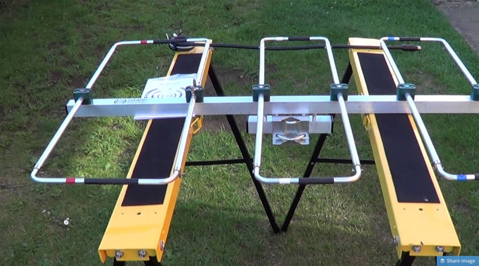
 A portable 4 elements quad antenna for 144 MHz, 9 to 10 DBd forward gain, 30 DB front-to-back ratio, and 33 DB front-to-side ratio
 -
 A three element wire yagi antenna for 7 MHz project plan with drawings and EZNEC model
 -
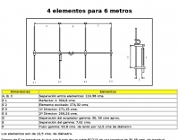 Project plan for a 4 element yagi beam for 50 Mhz
 -
 A copper pipe Hentenna for 144 MHz. The Hentenna, a compact, high-gain loop antenna developed in Japan in the 1970s, offers approximately 5.1 dBd gain, comparable to a three-element Yagi. Adapted for 2 meters, it is crafted from copper pipe for simplicity, affordability, and broadband performance. Requiring no feed-point tuning, its construction involves soldering standard copper fittings. Installation demands non-conductive materials to minimize signal disruption. Versatile for vertical or horizontal polarization, it is ideal for FM, repeater, SSB, or CW applications. This design emphasizes practicality and performance for amateur radio enthusiasts
 -
-
 One popular rumor or thought is that antenna gain doubles every time we double the number of elements
 -
 Presents a detailed construction guide for a **Quadrifilar Helix Antenna** (QHA) optimized for 137 MHz, specifically for receiving weather satellite transmissions. The resource outlines the author's experience building previous QHA designs, highlighting challenges with tuning and nulls, and then focuses on a refined design by John Boyer, documented by Steve Blackmore, which proved easier to build and yielded superior reception. The guide provides precise element dimensions, including 1.5m of 32mm PVC pipe for the mast and 8mm soft copper tubing for the helix elements. It specifies lengths for horizontal tubes (190mm, 90mm) and helix elements (903mm, 1002mm), along with instructions for drilling, assembly, and forming a **balun** by wrapping RG58 coax around the mast. The text emphasizes critical steps like ensuring elements are square and twisting in the correct direction to avoid phase issues. It includes references to original QST articles by Buck Ruperto (W3KH) and the WxSat program for decoding satellite transmissions, contextualizing the antenna's purpose. The article concludes with a sample NOAA 12 image from September 1998, demonstrating the antenna's reception capabilities.
 -
 This resource details the conversion of an 80m elevated vertical antenna to include 160m operation, focusing on a relay-switched design over a trap-based approach. It presents specific feedpoint impedance values, such as **32 ohms** for 80m and **14 ohms** for 160m, and discusses the challenges of SWR drift encountered with the prior trap system during RTTY contesting. The article thoroughly explains the design choices for elevated radials, referencing _N6LF QEX data_ to debunk common myths regarding radial length and height, demonstrating that non-resonant radials can offer superior current uniformity. The construction section provides practical insights into building the vertical, including guying strategies, material selection from scrap pipe, and weatherproofing the relay assembly. It highlights the use of a common mode choke for the relay switching line, measuring approximately 5K ohms on both 160m and 80m, and details the L/C matching network's role in achieving a 50-ohm match at the end of a 300-foot RG-11 run. The author describes a precise VNA-based radial trimming procedure, achieving resonant values within a 3 KHz range. The content emphasizes the practical application of theoretical antenna principles, particularly concerning the interaction between the vertical element, cap hats, and the matching network. It offers a candid assessment of component selection, such as using junkbox parts and acknowledging the need for future upgrades to static drain resistors. The article serves as a comprehensive case study for advanced antenna builders tackling multi-band vertical designs.
 -
 Demonstrates the design and construction of a 9-element Yagi antenna for the **70 cm band** (432 MHz), based on the DK7ZB concept. The resource details EZNEC+ calculations for a single antenna, providing gain, sidelobe suppression, and front-to-back ratio figures. It also presents a comprehensive analysis of stacking two such antennas, including optimal stacking distance (1000 mm) and the resulting performance enhancements for the stacked array, such as an increased gain of 17.03 dBi. The article includes detailed drawings, wire file dimensions in millimeters, and azimuth/elevation plots for both single and stacked configurations. Practical construction steps are documented with original photographs, illustrating element mounting, the **28 Ohm matching system** using two quarter-wave 75 Ohm transmission lines, and the critical N-connector wiring. It also covers the iterative process of fine-tuning the driven element length to achieve a return loss of 20 dB, validating the EZNEC+ simulation results with actual measurements.
 -
 VA3EXT 5 element beam antenna for 6 meters band
 -
 Here is a way to ease assembly and balancing of a large antenna. The elements and boom are assembled separately in most cases. Once they are all together set up 2 tripods in the assembly area and put the boom on them.
 -
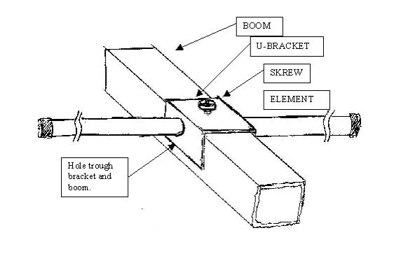 Here is an easy method to mount elements to a boom, this can be realized at home, without the need of special tools
 -
 Anyone attempting to work DX on Top-Band 160 Meters, soon learns of the need for a good receiving antenna. This is a 160 meter 8 element receiving array.
 -
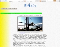
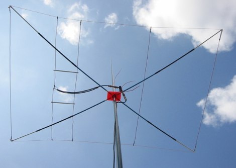
 The antenna is a vertical dipole, around which four parasitic elements are forming a circle.
 -
 An old project by I1VCF for a 3 element yagi antenna originally designed for 10/15/20 and extended to 24 and 18 Mhz in Italian
 -
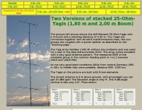 Two Versions of 5 elements stacked 25 Ohm Yagis with 1,80 m and 2,00 m Boom
 -
 A five element quad antenna for 144 MHz DIY Project. This 2 Meter 5 Element Quad antenna was modeled using EZNEC, with a boom from a UHF TV antenna and CPVC pipe for spreaders. Constructed for 146MHz, it exhibits a gain of 10.7dB and an impedance of 75 ohms. Real-world results surpass the HT antenna, reaching over 20 repeaters up to 75 miles away. The design, costing around $10, employs simple tools for assembly.
 -
 Enables users to convert plain text into _Morse Code_ and, conversely, decode Morse sequences back into readable text. This web-based utility provides a straightforward interface for rapid translation, proving useful for both learning and practical application. It processes input efficiently, displaying the corresponding Morse or text output instantly. Operators can leverage this tool for generating practice copy or for deciphering received CW signals, making it a handy resource for those honing their code skills. The translator handles various character inputs, converting them into standard International Morse Code elements. This simple utility supports quick lookups and real-time conversions, facilitating a better understanding of CW structure and timing. It operates entirely online, requiring no software installation.
 -
-
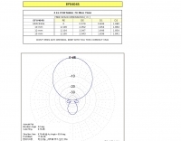
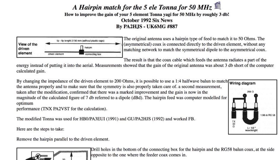 An interesting modification to improve the gain of your 5 element Tonna Yagi beam for 50 MHz by roughly 3 db!
 -
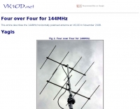 This article describes the 144MHz horizontally polarised antenna at VK1OD in November 2008. The antenna uses two identical four element arrays that were constructed around 1970
 -
 Demonstrates the product line of _LZ Antenna Ltd._, a Bulgarian manufacturer specializing in amateur radio antennas and custom electronic devices. The company focuses on robust, high-quality HF multiband Yagi and vertical antennas, leveraging over 20 years of experience from founder Georgi Georgiev in radio amateur development. Featured models include the LZA 8-4, LZA-10-3, and the LZA-7-3A WRTC 2022, alongside various rotary dipoles like the LZA1 40/30m. Provides specifications for several Yagi antennas, such as the LZA-9-5, LZA-13-7, and LZA-6-3 (a 6-element, 3-band design). The company emphasizes applying "leading edge technology" to high-frequency communication equipment production, with products designed for durability and performance. The LZA-10-5 Yagi offers **12.5 dBi** gain on 10m, while the LZA-13-7 provides **13.2 dBi** on 20m, showcasing competitive gain figures for DXing and contesting.
 -
 An antenna originally planned in the sixties, a two element beam antenna tunable on several band, in french
 -
 Presents a construction project for a linear-loaded 40-meter rotatable dipole, detailing the design evolution from mid-element coils to 300-ohm twinlead loading. It covers material selection, including repurposed fishing poles and EMT conduit, and outlines the assembly process for the antenna elements and mounting plate. The resource provides specific measurements for element lengths and linear loading sections, along with SWR plots demonstrating the antenna's resonance at 7.035 MHz with a 1.1:1 SWR, and bandwidth up to 7.120 MHz below 2:1 SWR. The article documents the antenna's performance during various RTTY and CW contests, including the SARTG RTTY and SCC RTTY contests in August 2006, and the ARRL DX CW and CQWW WPX RTTY contests in February 2007. It reports successful operation at 500-1000W, noting improved performance after replacing a faulty coax cable. Specific DX contacts from British Columbia, including stations in Europe and South Africa, are listed, illustrating the antenna's capability despite its shortened length and relatively low height of 55 feet. The content highlights practical considerations such as weatherproofing the connections and supporting the fiberglass elements to prevent sagging. It also includes a brief comparison to an inverted-V at similar height and a ground-mounted vertical, noting the rotatable dipole's quieter reception. The author shares insights into the iterative design process and tuning adjustments made to achieve optimal resonance.
 -
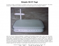 Add two parasitic elements to the sleeve dipole of a Netgear Router
 -
 About beverage antennas, Enhanced F/B Beverages, Bandwidth of Directivity, arrays. This article describes two phasing systems for Beverage antennas that improve directivity and cancel rearward signals. These systems use lossy elements and require minimal components to achieve broadband performance.
 -

-
 Presents the design and performance of a 4-element wire Yagi antenna for the 40-meter band, building upon VE3VN's earlier 3-element switchable wire Yagi. The resource details the antenna's evolution, highlighting the transition from a 3-element to a 4-element configuration and the resulting improvements in gain and front-to-back ratio. It provides specific insights into the antenna's construction and expected operational characteristics. VE3VN shares insights from field results, noting the antenna's performance on 40 meters. The discussion includes the antenna's pattern and matching characteristics, crucial for any DXer or contester looking to optimize their signal on this popular HF band. The author's experience with the previous 3-element design informs the enhancements made to this 4-element iteration. The article includes a visual representation of the antenna's current view, offering a practical perspective on its physical layout. It serves as a valuable reference for hams considering a directional wire antenna for 7 MHz operations, demonstrating a practical approach to achieving enhanced directivity and gain.
 -
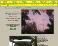
 Demonstrates the design and construction of a compact, portable multi-band mini-delta loop antenna, specifically optimized for /P (portable) operations from remote locations like Scottish islands. The resource covers the theoretical underpinnings of half-wave loops, contrasting closed and open configurations, and then details the application of a folded dipole principle to achieve a 50-ohm match for direct coax feed. It presents empirical formulas for calculating element lengths, considering the velocity factor of common wire types, and provides a detailed example for a 20m (14.175 MHz) version. The article includes a comprehensive table of dimensions and allowances for a five-band (20m, 17m, 15m, 12m, 10m) mini-delta beam, along with construction hints for the central support and balun. It specifies a 1:1 trifilar balun wound on a ferrite rod and describes the antenna adjustment process using an _MFJ-259B Antenna Analyser_. Initial test results indicate an SWR of 1:1 at resonance and a bandwidth of approximately 240 kHz on 20m, even at a low height of five feet above ground. The distinctive utility lies in its focus on a practical, easily deployable beam antenna for portable DXing, offering a viable alternative to more complex or larger arrays.
 -

-
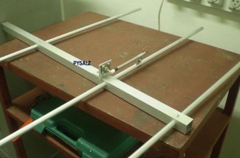 A 3 element yagi antenna project for the 144 MHz band by PY5ALZ in portuguese
 -
 On this page is the design for Dual Band 2M / 70cm antenna with 3.2mm elements. The antenna has a 50 ohm designed driver. This Yagi has a unique element called a Open Sleeve
 -
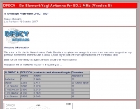 Christoph petermann's df9cy six element yagi antenna for six meter band
 -
 Design plan of an array of a two element yagis for 80m and a 3 element 40m antenna sharing a single 12 meters long boom by EA5DY
 -
 This program demodulates the telemetry data signal transmitted by the AO-40 satellite (aka Phase III-D) using the PC sound card
 -
 Construction details and tests about a 2 elements cubical quad antenna for HF Bands (20,17,15,12 and 10m band).
 -
-
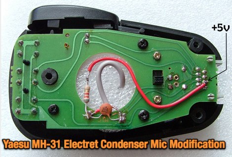 An unused 5v supply connection allows an electret condenser microphone element to be used in place of the standard dynamic element. Modification by M0UKD
 -
 Presents the DBO274 Citizen Band mailbox, a digital communication hub accessible via HTTP and Telnet, specifically catering to **CB radio** enthusiasts in Germany. This resource outlines its functionality for Packet and other digital emissions on the 11-meter band, a segment often overlooked by traditional amateur radio operators but vital for CB users seeking advanced communication methods. The author, DH8YMB, provides insights into its operation, reflecting practical experience with digital modes in the CB spectrum. The DBO274 serves as a bridge, enabling users to exchange messages and data packets, extending the reach and utility of standard CB transceivers. It represents a localized digital infrastructure, demonstrating how the 27 MHz band can support more than just voice contacts, incorporating elements of early internet-like communication within the CB community. This setup highlights the enduring innovation within the CB realm, adapting technologies like Packet Radio for a different user base. It underscores the versatility of radio communication, even on less conventional bands, for those interested in digital data exchange beyond the typical amateur allocations.
 -
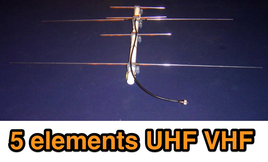
 A project for a home made 5 element yagi-uda antenna for 2 meters, covering 144-148 MHz band by N1BMX
 -
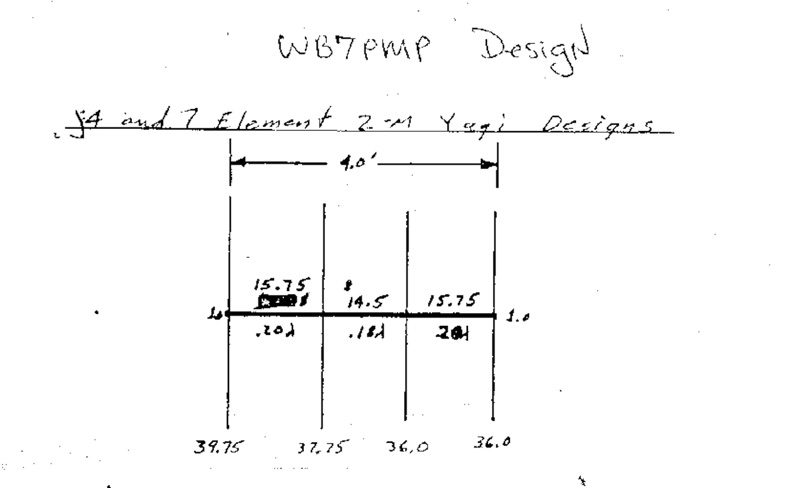 Original drawing and design of a 4 and 7 elements yagi antenna for 50 Mhz
 -
 SimSmith is a highly interactive, real time Smith chart graphing program. Circuits are constructed using drag-n-drop. Load files can be imported from the EZNEC and CocoaNEC antenna simulation software and from the AIM4170 and miniVNApro antenna analyzers. Circuits and load files can be of any size. Key Features: SimSmith is one of the few Smith chart packages which models transmission line losses. SimSmith also allows the description of circuit elements using algebraic equations. SimSmith has only one screen and allows the screen to be resized to increase workspace or readability.
 -
 Collection of different techniques to homebrew PVC yagi antennas, including elements assembling, baluns and chokes, radiator box tips and tricks by dk7zb
 -
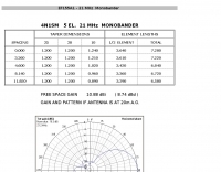
 Design for a 5 element 2 Metre beam with a forward gain of 8dBD and a front to back ratio of over 24dB.
 -
