Search results
Query: frequency antenna
Links: 225 | Categories: 5
-
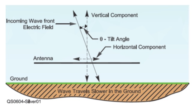
 This article focus on the radiation angle of vertical antennas and the fundamentals of electromagnetic wave propagation. The calculation of antenna length at 145 MHz is followed by an explanation of electromagnetic wave speed and the link between wavelength, frequency, and velocity. Author discusses the 5/8th wave vertical antenna, namely its performance and the influence of radiation angle on signal transmission. Figures and analogies demonstrate how different antenna types produce distinct radiation patterns. This highlights the importance of selecting the right antenna for a certain purpose, such as local traffic or dxing. The article discusses a variety of factors that affect antenna performance, including SWR, propagation conditions, and equipment dependability
 -
 AutoEZ, Automated use of EZNEC, is an Excel workbook that works alongside EZNEC antenna modeling software version 5.0 or later. With AutoEZ, you can control different aspects of your model using variables and run multiple EZNEC test cases automatically. Formulas in Excel allow you to modify any part of the model. AutoEZ's interface resembles EZNEC's. Enabling macros in Excel might be necessary before using AutoEZ. The program opens various model file formats including EZNEC (.ez), NEC (.nec or .inp), AO and NEC/Wires (.ant), and MMANA-GAL (.maa). You can set the frequency and/or variable values for the test cases to be run through EZNEC. AutoEZ allows you to create animations showcasing how the pattern changes as the model configuration is modified. You can download a fully working, but limited demo copy from this site.
 -
 OM0ET manufacture high capacity variable air capacitor and tuning unit designed for Magloop antennas. OM0ET explains features and benefits of this antenna, such as easy assembly, wide frequency range, and improved efficiency. Ideal antenna setup for indoor or outdoor use, offering better QSO performance and radio listening experience. The author, identified as OM0ET, shares insights on the design and functionality of the equipment, making it a valuable antenna for portable operations.
 -
 This article published on QEX details measurements of tree conductivity and permittivity at HF frequencies, addressing a long-debated topic in amateur radio. N6LF conducted experimental impedance measurements on Douglas fir and maple trees using a vector network analyzer with rings of nails inserted into tree trunks. Results showed that tree conductivity increases with frequency while relative permittivity decreases, similar to soil characteristics. Measured conductivity ranged from 0.06 to 0.4 S/m at 10 MHz, aligning with values used in previous research. These findings validate that NEC modeling can reliably estimate trees' substantial impact on HF antenna performance.
 -
 Effective suppression of harmonics and parasitic radiation from HF transmitters is crucial, especially with the increasing sensitivity of VHF/UHF radio channels to interference. This project details a hybrid low-pass filter (LPF) designed to operate across the HF bands up to 51 MHz, making it suitable for 6-meter band operations while providing deep VHF/UHF suppression. The design addresses the challenge of modern interference landscapes, where even microvolt-level signals can disrupt wireless sensors and other simple VHF/UHF receivers. The filter utilizes a single elliptic link, combining high cutoff steepness with robust suppression in the hundreds of megahertz range. A key feature is the use of only two standard capacitor values, simplifying construction and component sourcing. The article provides a detailed schematic, performance characteristics, and _RFSim99_ model file, demonstrating a reflection coefficient S11 below 0.017 (VSWR < 1.03) across 1-51 MHz, ensuring minimal degradation to the antenna system. Construction notes include coil winding specifications and capacitor selection guidance, with recommendations for _FR-4_ assembly. Two capacitor sets are presented, with the first variant recommended for its lower RF current demands, keeping currents below 3 A at 1 kW passing power at 51 MHz. Fine-tuning involves adjusting frameless coils, with considerations for capacitor tolerance and high-frequency capacitance measurement accuracy.
 -
 Compare the efficiency of two HF (or VHF) antennas by simultaneously transmitting FT8 on nearly the same frequency and analyzing PSKReporter SNR data. Determine the effectiveness of your new antenna compared to the old one in dB, to several decimal places. Run FT8 on two transmitters with different call signs and equal power, connected to each antenna. AntennaCompare analyzes global signal reports, isolating antenna performance.
 -
 This **PDF report** documents a _maritime mobile_ DXpedition operating from the _Southern Ocean_ near Antarctica, detailing antenna deployment strategies on a sailing vessel. It addresses power management systems for remote operations and propagation characteristics specific to polar regions on **20m and 40m** bands. Operational strategies include managing high-density pileups using split frequency operation and maintaining signal integrity during periods of high aurora activity. Equipment considerations cover specific transceiver models like the Icom IC-7300, antenna types optimized for marine vessel installation, and battery power systems for extended periods without shore power. The resource also examines the use of satellite communication for real-time log uploads and QSL confirmation from remote locations, and discusses mitigating signal degradation from ice accumulation on antennas. DXZone Focus: PDF report | Maritime Mobile DXpedition | Polar Propagation | Split Frequency Operation
 -
 When installing a mobile antenna, optimal placement significantly impacts performance. Factors such as gain, antenna type, ground plane availability, mounting style, and environment must be considered. Antenna designs, such as 1/4 wave and 5/8 wave, have distinct radiation patterns ideal for specific settings—urban areas or flat terrains, respectively. Ground plane size requirements differ by frequency, impacting effectiveness. Among vehicle mounting options, the car roof center provides the best ground plane and minimal obstruction, ensuring peak performance, especially at higher frequencies like 800 MHz.
 -
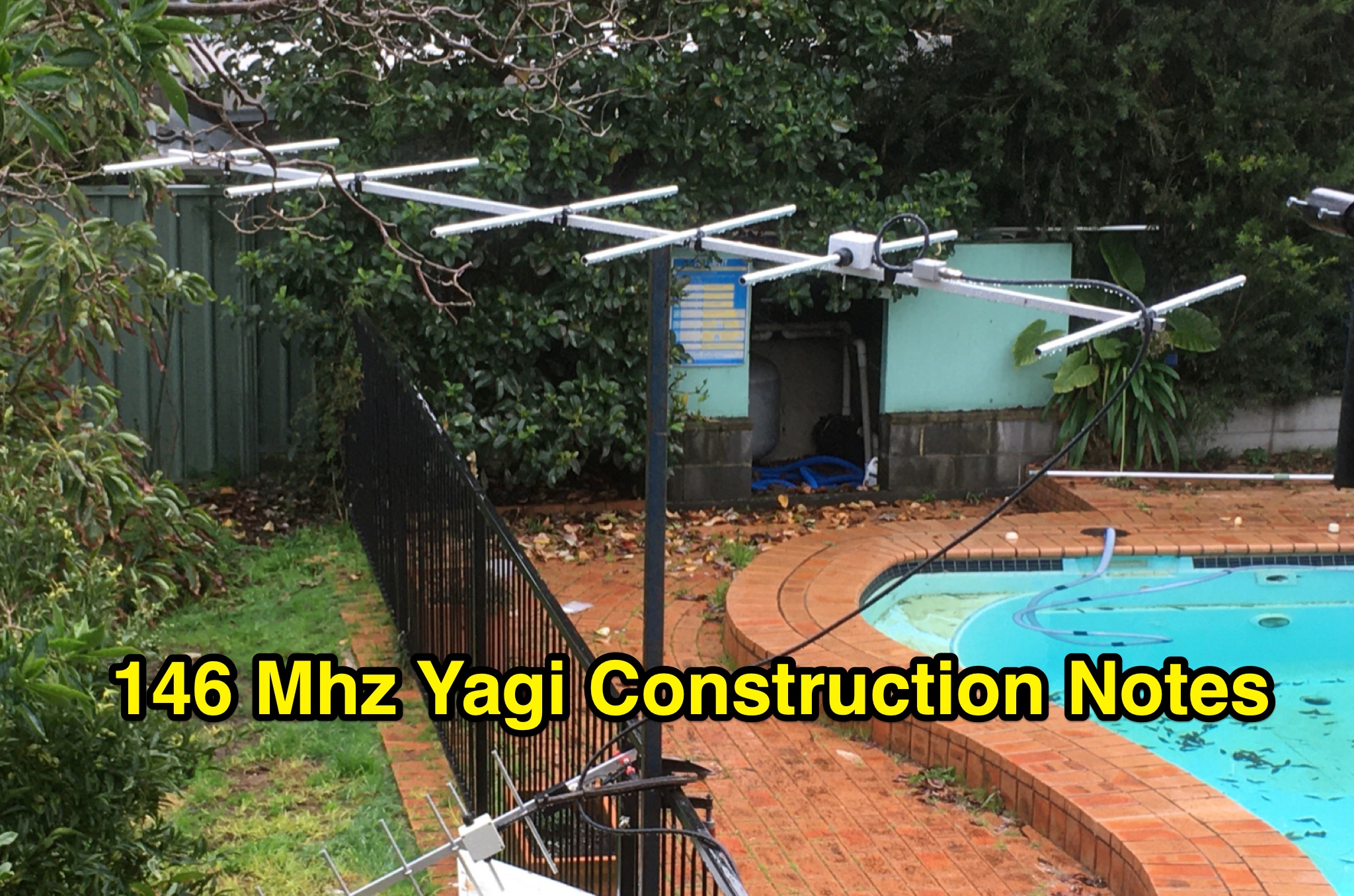 This PDF document contains construction notes for a Yagi antenna designed for the 146 Mhz frequency range. It provides detailed instructions and information on how to build the antenna, making it a valuable resource for hams looking to improve their radio setup. The document covers the materials needed, step-by-step construction process, and tips for optimizing performance. Whether you are a beginner or an experienced ham radio operator, these construction notes can help you enhance your antenna system for better communication.
 -
 This article explores the powerful features of AutoEZ as an Excel application working with EZNEC antenna modeling software. The article demonstrates how variables, equations, and formulas enable versatile antenna design and automatic optimization. Through practical examples including dipoles, inverted vees, delta loops, and monopoles, the author shows techniques for achieving resonance, implementing transmission line resonators for broadbanding, and optimizing antennas across frequency ranges. The step-by-step demonstrations cover unit conversion, coordinate calculations, segmentation considerations, and SWR optimization. This practical guide illustrates how AutoEZ extends EZNEC's capabilities, making complex antenna modeling more efficient and accessible.
 -
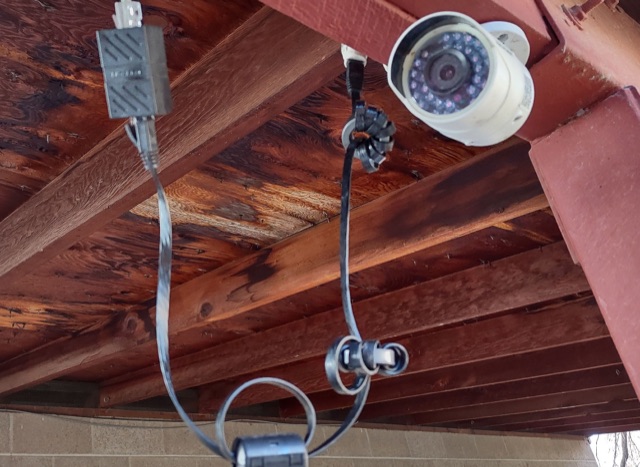 Hams can be annoyed by noise from PoE cameras and access points. These devices and their long cables act like antennas, picking up and spreading unwanted radio signals. By wrapping ferrites around the cable will reduce this noise. It won't silence it completely, but it can make a big difference.
 -
 This is a theoretical look at propagation on 630-Meters and 2200-Meters using ray tracing software. It expands on the brief discussion in the ARRL Handbooks. The Earth's magnetic field affects 630-Meter and 2200-Meter band propagation. Lower ionization reduces absorption, aiding low-frequency propagation. Differences exist between bands, limited daytime sky-wave propagation. Sunrise/sunset show promise, yet mechanisms are unclear. Ducting possible at night in specific conditions. Negative ions enhance propagation. Inefficient antennas and high man-made noise are anticipated. Groundwave propagation is significant on 2200-Meters.
 -
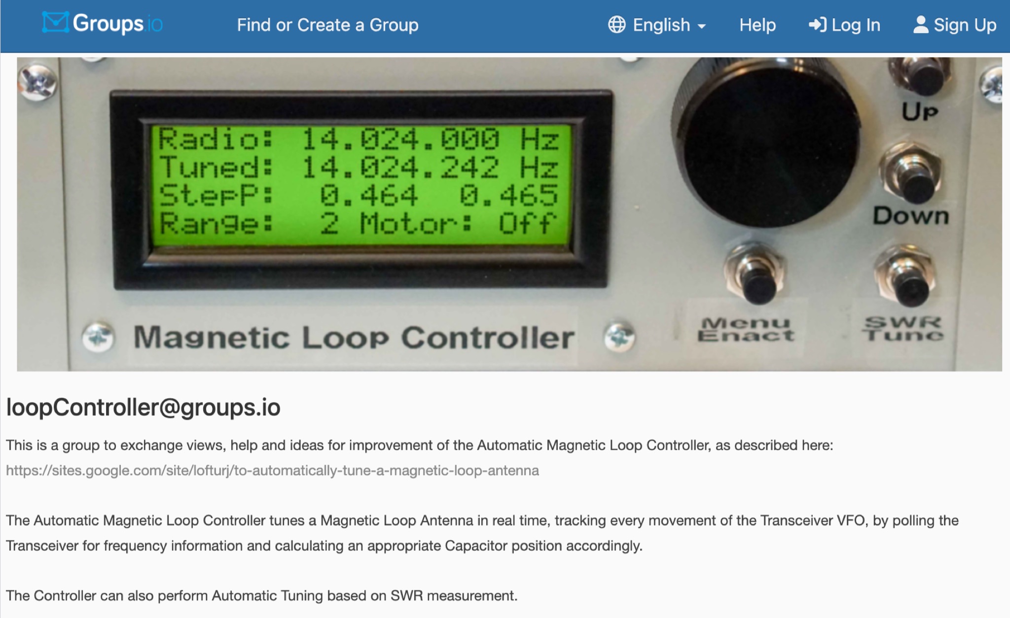 This is a group to exchange views, help and ideas for improvement of the Automatic Magnetic Loop Controller, as described at VE2AO web site. The Automatic Magnetic Loop Controller tunes a Magnetic Loop Antenna in real time, tracking every movement of the Transceiver VFO, by polling the Transceiver for frequency information and calculating an appropriate Capacitor position accordingly. The Controller can also perform Automatic Tuning based on SWR measurement.
 -
 This resource details the construction and performance of a compact broadband magnetic loop antenna designed for portable receiving applications with devices like the _ATS MiniRadio_. The antenna utilizes approximately 3 meters of 0.5–1 mm copper wire wound in two turns on a rhomboidal wooden frame, measuring 50 cm by 70 cm. It connects via a modified 9:1 unun, where the primary center tap is isolated from ground to improve common-mode noise rejection. The design provides untuned operation across a frequency range from the longwave band up to approximately 25 MHz. Performance characteristics include observable directivity for noise suppression and the ability to connect directly to a radio or via a 50 coaxial cable for remote operation. The article specifies the unun's 3:1 turns ratio and its SMA output for connectivity. The methodology focuses on practical construction and observed reception quality.
 -
 YAGio 1.01 is a Windows-based software for designing DL6WU long Yagi antennas on VHF and UHF frequencies. It supports Windows 2000, XP, Vista, 7, and likely 8. Using keyboard commands, users input specifications such as frequency, gain, and element diameters, and YAGio generates the design. You can download latest Yagio version from this page. Results can be saved in YIO, NEC, YAG, MMA, and YC6 formats, or printed directly.
 -
 This article explores Beverage antennas, a type used for low-frequency radio reception. Despite the mystique, they are relatively simple wire antennas placed near the ground. Their key benefit is improved signal-to-noise ratio by rejecting unwanted signals. While lengthier antennas offer better reception, even shorter versions (around 200 feet) can improve DX reception compared to traditional antennas.
 -
 145 MHz is the target frequency for this 2-meter Skeleton Slot Yagi Stack antenna project. The design focuses on feeding two stacked Yagi antennas using a skeleton slot radiator, which is a unique approach for VHF enthusiasts. The project details the construction process, including the loop tapered matching section for impedance matching, ensuring optimal performance. The use of specific components like the EH789 element holder and MB456 main mast bracket is highlighted, providing clarity on the assembly process. The construction utilizes 20x20 box aluminum bar for durability and precision. Key dimensions, such as the element length (ER-ED4) and main boom spacing (MM123), are meticulously outlined. This attention to detail aids in replicating the antenna design accurately. The downloadable PDF offers comprehensive instructions, making it accessible for amateur radio operators interested in VHF antenna construction. This project is particularly beneficial for those looking to optimize their 2-meter band operations. The inclusion of a skeleton slot radiator and loop tapered matching section demonstrates advanced techniques in antenna design, catering to both intermediate and advanced builders.
 -
 Twenty 1-watt carbon film resistors are configured in parallel to construct a 50-ohm **dummy load** for amateur radio applications. The design incorporates a heatsink for thermal dissipation and an **SO-239 connector** for RF input, making it suitable for QRP operations. This budget-friendly project details component selection, soldering techniques, and mounting procedures, achieving a continuous power rating of 10 watts and intermittent handling of up to 100 watts across HF and VHF frequency ranges. The resource provides a step-by-step guide for assembly. This construction offers an economical solution for essential shack tasks such as antenna tuning, transmitter testing, and SWR meter calibration without radiating an RF signal. The utilization of readily available components significantly reduces the overall build cost compared to commercial alternatives, providing radio amateurs with a functional and reliable test accessory. While specific VSWR measurements are not provided, the design prioritizes practical utility for low-power transceiver diagnostics and general RF experimentation.
 -
 This page by Arctic Peak provides a detailed explanation on how to use quarter-wave transmission lines as impedance transformers in ham radio antenna work. It explains how to match impedance values by connecting them with a λ/4 transmission line. The page also offers guidance on constructing your own transmission lines with specific impedance requirements, along with a calculator to determine the quarter wave length based on velocity factor and frequency. Useful for hams looking to optimize antenna performance and match transmission line impedance effectively.
 -
 The Gemini Amplifier Remote Control software operates on Windows 7 and above, facilitating remote management of the Gemini HF-1K and DX-1200 amplifiers. Users connect via Ethernet, configuring the amplifier's IP address through the front panel. The software allows seamless band and antenna selection, saving settings for each band without requiring transmission. Integration with _OmniRig_ from Afreet Software, Inc. enables automatic band adjustments based on the radio's frequency changes. Users can configure serial or virtual serial connections, with tracking options accessible through the ribbon bar. The software supports speech functionality, enhancing accessibility for operators. Firmware updates, such as version 2.5Ee, introduce features like background datalogging and power output control, uploaded via FTP. Version 1.2.0 allows users to offload internal parameter data for support purposes. The firmware upload process requires the amplifier's IP address and port 21, taking approximately 90 seconds. Users are encouraged to upgrade to the latest firmware for improved performance and remote diagnostics.
 -
 Demonstrates the construction of an active loop converter specifically designed for the Low Frequency (LF) bands, addressing common localized noise interference in LF reception. The design integrates a sharply tuned circuit and a tuned loop antenna, utilizing the loop as the sole tuned inductive element. By applying positive feedback, the converter significantly increases the loop's effective Q, achieving factors between 1000 and 2000, which sharpens tuning and reduces noise. The circuit employs an _NE602_ mixer stage, feeding its output to an HF receiver, with a crystal-locked local oscillator at 4 MHz. A 20-turn, 0.8-meter square loop antenna with 500 uH inductance is detailed, connected via 2 meters of figure 8 flex cable. The converter offers three selectable frequency bands: 195-490 kHz, 150-220 kHz (including the New Zealand amateur band), and 128-160 kHz (covering the European amateur band). Performance measurements indicate an effective 3dB bandwidth of approximately 100 to 200 hertz at 200 kHz. The article provides insights into component selection, including an _LF353_ op-amp and a trifilar wound transformer on a ferrite core. Sensitivity figures are presented, showing 7.5 uV of converted output per 1 uV/meter signal strength into a 50-ohm load, or 37.5 uV into an _FRG7_ receiver, highlighting its capability to extract weak signals from noise.
 -
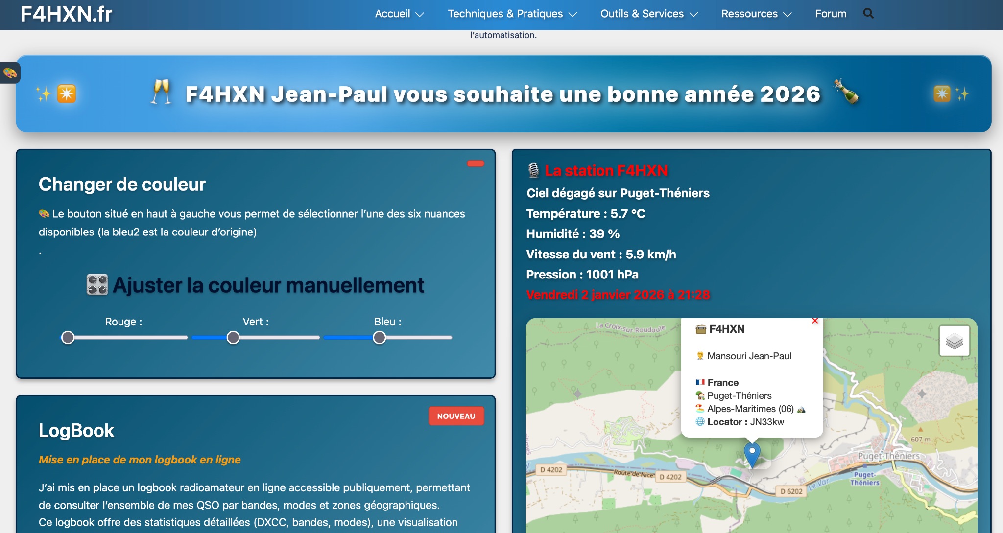 Demonstrates various technical projects and tutorials for amateur radio operators, focusing on digital modes, monitoring, and station setup. It covers topics such as implementing a _WSPR_ station, setting up ADS-B reception, configuring a _DXSpider_ cluster, and utilizing monitoring tools like Prometheus and Grafana. The resource provides practical guides for integrating modern IT solutions with ham radio activities, including Docker and Linux environments for radio applications. This site also features a publicly accessible online logbook, offering detailed statistics on QSOs by band, mode, and geographical zone, with visual mapping of contacts. It includes a comprehensive amateur radio lexicon, explaining hundreds of terms, and provides a real-time display of the F4HXN station's local weather conditions. The resource also aggregates information on upcoming ham radio events and offers a **SWR simulator** for antenna analysis, allowing users to visualize ROS changes based on frequency and antenna parameters.
 -
 This page provides a detailed example of the modeling and analysis of an 80m delta dipole antenna with a 600-ohm bifilar feedline. The model is based on antennas used by the RAF from 1940 to 1970. It covers the original model specifications, conductor mass calculations, resonance frequency observation, geometry adjustment steps, and final antenna dimensions. The content includes theoretical formulas, resonance frequency calculations, and practical steps for adjusting the antenna for optimal performance. Overall, it serves as a practical guide for hams looking to understand and optimize the performance of a delta dipole antenna for the 80m band.
 -
 The W6PQL 23cm Beacon Project describes a **1296 MHz** beacon designed for microwave propagation studies and equipment testing, capable of 30 watts output. It utilizes a PIC 16F628A microcontroller to generate CW and FSK keying for a crystal oscillator, followed by a series of frequency doublers and triplers to reach the target frequency. The final power amplification stage employs a Mitsubishi M57762 module, providing a robust 10-watt RF output. The design emphasizes stability and reliability for continuous operation, with the microcontroller code, written in assembly, provided for customization of the beacon's callsign and message. Originally located in CM97am and aimed at 140 true, the beacon used four 4-foot Yagis stacked vertically for a total ERP of 3kW. The article includes schematics, parts lists, and construction notes to guide builders, along with antenna pattern measurements. Although the beacon itself is no longer in service as of August 2010, the detailed documentation remains a valuable reference for amateur radio operators interested in building similar **microwave** projects or understanding beacon operation.
 -
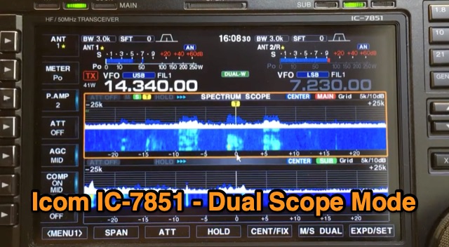 The Icom IC-7851 features the capability to display two scopes simultaneously, providing frequency, mode, and antenna information for each receiver. Users can choose between vertical or horizontal display orientations, and the dual scopes are also viewable on a high-resolution monitor connected to the radio. Additionally, the IC-7851 allows for mouse connectivity, enabling users to click on signals displayed on either scope for quick tuning. A demonstration video is available showcasing this dual scope functionality.