Search results
Query: schema
Links: 260 | Categories: 72
Categories
- Antique Radios > Schematics
- Antennas > Baluns > 1 to 1 Balun
- Antennas > 20M > 20 meter Vertical Antennas
- Antennas > Baluns > 4 to 1 balun
- Operating Modes > Amateur Television
- Technical Reference > Amplifiers
- Technical Reference > Antenna Rotator
- Technical Reference > Antenna Switch
- Technical Reference > APRS
- Technical Reference > Attenuators
- Technical Reference > ATV
- Technical Reference > Audio
- Technical Reference > Beacon keyers
- Radio Equipment > HF Vertical Antenna > Butternut HF2V
- Antennas > Capacitive
- Technical Reference > Components
- Technical Reference > Receivers > Crystal radio
- Technical Reference > Digital ATV projects
- Radio Equipment > Receivers > Drake R-4B
- Technical Reference > DTMF
- Technical Reference > Dummy Loads
- Technical Reference > Duplexers
- Antennas > EH
- Antennas > End-Fed > End Fed Half Wave Antenna
- Technical Reference > Frequency Counter
- Antennas > HB9CV
- Technical Reference > Headsets and Speakers
- Technical Reference > HF Radios
- Technical Reference > Homebrew
- Antennas > Horn
-
 Le radioamateurisme,le qrp,l elecraft k2, antennas,qrp,schemas,manuals,nostalgia, meteo,dx clusters hf, and contests links in french
 -
 Schematic of a fast charger for Gel Cell batteries
 -
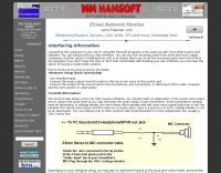 Demonstrates the fundamental principles for connecting a personal computer to a ham radio transceiver, specifically for utilizing sound card-based digital mode software like those in the MM Hamsoft suite. It details the basic hardware setup, emphasizing the use of shielded leads and proper audio routing from the radio's output to the sound card's input, and from the sound card's output to the radio's microphone or data input. The resource highlights the critical need for transmit attenuation, suggesting a 100:1 voltage divider to prevent overdriving the transmitter's audio stage, and mentions the optional addition of ferrite beads and decoupling capacitors for RFI mitigation. The guide also points to external resources for more detailed pin-outs and interface schematics, such as a specific QSL.net page, and recommends consulting the help files within MM Hamsoft programs for interfacing specifics. It underscores that while the process is straightforward, understanding the audio level management and proper cabling is key to successful operation. The author, VE5KC, provides practical advice drawn from common issues encountered by operators setting up digital mode stations.
 -
 Sams Photofact download Schematics and Service Manuals, Originals and downloads.
 -

-
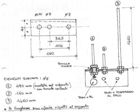 A multiband J-Pole antenna project that cover 144,220 and 430 MHz. The articles includes several pictures of this multi-band antenna, including handmade schematics and diagrams, project is mainly in Italian
 -
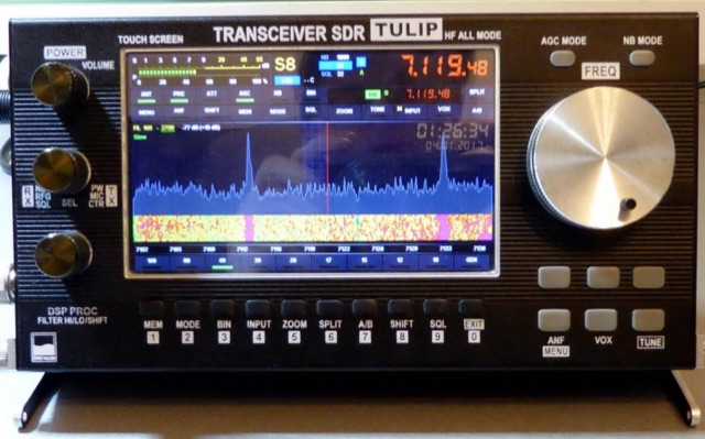 SDR Project for a compact amateur radio software defined radio trasceiver covering HF bands all mode. Website includes schematics, element PCB, pictures, movies, firmware and elements bom.
 -
 Schematic diagram for a high voltage power supply by W4NFR
 -
 DTMF Keypad for radios without one. A project with picture and schematic diagrams to homemade a DTMF keppad
 -
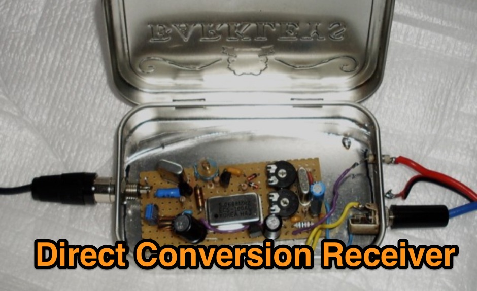 A schematic diagram of a homemade direct conversion receiver for 30 meters band
 -
 Demonstrates the construction of a high-power 6-meter (50 MHz) amplifier, specifically designed for demanding modes like EME, TEP, and multiskip Es. It details the use of a _GU-43B_ tetrode in a grounded-cathode configuration, emphasizing the need for stabilized grid voltage and input capacitance compensation. The resource provides a comprehensive schematic, power supply design, and practical considerations for component sourcing, particularly for high-voltage and high-current sections. The builder achieved an output power of **1250 watts** with an anode current of 0.65 amperes and 3200 volts anode voltage. The article also covers the physical construction within a modified P6-31 enclosure, outlining the internal layout for RF and power supply sections, and includes photos of the completed unit. It highlights critical safety precautions for working with high voltages and reactive currents up to **20 Amperes** in the P-network.
 -
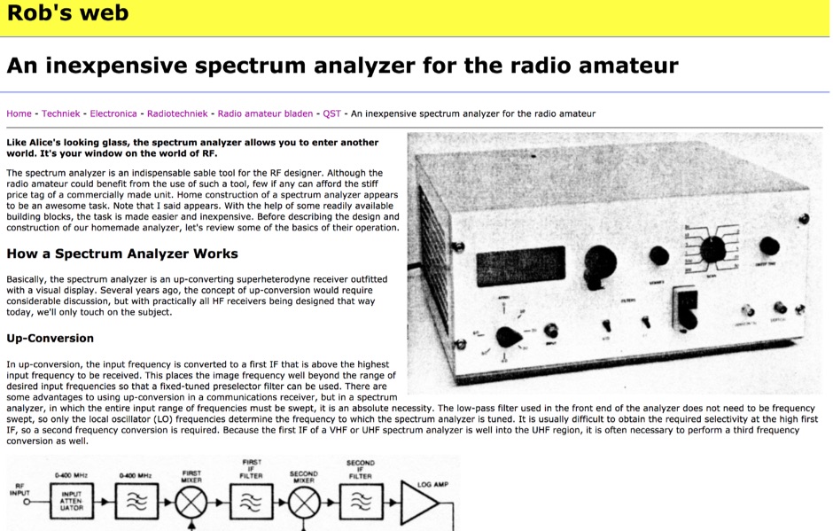 An inexpensive spectrum analyzer for the radio amateur, with a respectable performance and a quite good dynamic range. Schematic and basic information on how spectrum analyzers works.
 -
 A netlist converter for moving schematic and PC board files from OrCAD/PADS to ExpressPCB format.
 -
 A Rig control CAT interface schematic suitable for both the Yaesu FT-817 and FT-100 transceivers.
 -
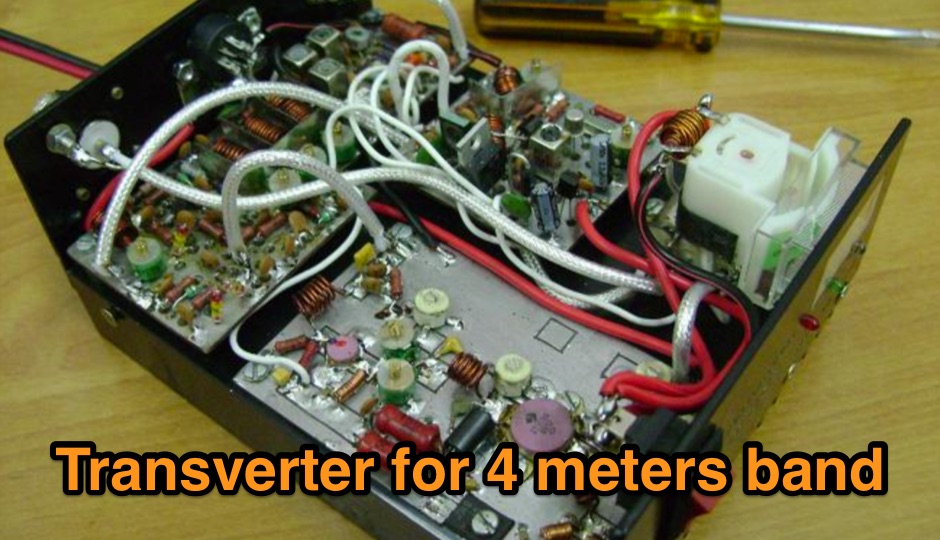 A 70 MHz Transverter project with a block diagram and schematics
 -
 Schematic diagram of a two tone audio oscillator by VK3YE
 -
 A 0-30 MHz step attenuator, constructed from switchable Pi attenuation pads, provides a practical tool for evaluating receiver sensitivity and calibrating S-meters. The design utilizes readily available 5% tolerance resistors, with values derived from paralleled components to achieve specific attenuation steps. A schematic (Fig 1) illustrates the circuit, including PCB pad shielding, while a table details required and actual resistor values, along with percentage differences. Measurements of voltage input versus output at various frequencies are used to calculate dB attenuation, presented in a graph (Fig 4). The resource includes formulas for determining output voltage from a known input and a comprehensive 0-40 dB voltage multiplier table, which is crucial for precise signal level management. The project also references external attenuator calculators and equations for further study. Photos (1-3) provide visual guidance for the assembled unit, showing bottom, top, and front views. The project emphasizes the use of **Pi attenuation pads** and **receiver sensitivity** evaluation, offering a hands-on approach to RF signal management.
 -
 Station QRP presents various **circuit diagrams** for constructing low-power AM vacuum tube shortwave transmitters, catering to enthusiasts interested in vintage radio technology. The resource details schematics ranging from simple to more complex designs, enabling hams to build their own QRP AM transmitters for operation on frequencies like 6.925 kHz AM. It emphasizes the use of vacuum tubes, providing a technical foundation for understanding and replicating classic shortwave broadcasting methods. The content is geared towards those who enjoy the hands-on aspect of electronics and the unique characteristics of tube-based RF circuits. Building these transmitters allows operators to experience the nostalgia of early shortwave radio, with the site specifically mentioning a pioneer station on 6.925 kHz AM. The designs facilitate experimentation with low-power AM transmission, offering practical application for homebrew projects. The focus on QRP (low power) operation aligns with a segment of the amateur radio community that values efficiency and minimalist setups, providing a distinct alternative to modern solid-state transceivers.
 -
 The W6JWS 2-meter Repeater Maintenance and Repair Log documents the ongoing upkeep of a 146.745 MHz repeater, specifically addressing modifications to enhance its functionality. It details changes made to ensure the repeater powers up in _PL mode_ and to improve the reliability of touch-tone control, drawing comparisons to similar work performed on the AE6KE repeater. The log also notes a repair to a fused wire in the reverse battery protection circuit after an accidental polarity reversal, highlighting a temporary workaround where a wire was omitted but the system remained operational. The resource includes practical insights from Jeff Liebermann, AE6KS, regarding jumper configurations and programming, with accompanying photos. It provides access to several documents for the Icom RP-1510 repeater, including operating manuals and a schematic for the single logic board version, which differs from the dual-board configuration described in some printed manuals. The log mentions a specific modification to adjust the dropout delay, which was later deemed unnecessary, and references a related project for the AE6KE repeater, aiming to replicate successful modifications on the W6JWS machine, resulting in improved touch-tone reliability and proper PL mode activation.
 -
 Fox Controller, designed by VE2JX and VE2EMM includes schematic diagram to build the transmitter.
 -
 A Fox transmitter by VE2EMM with construction details part list and schematic diagram
 -
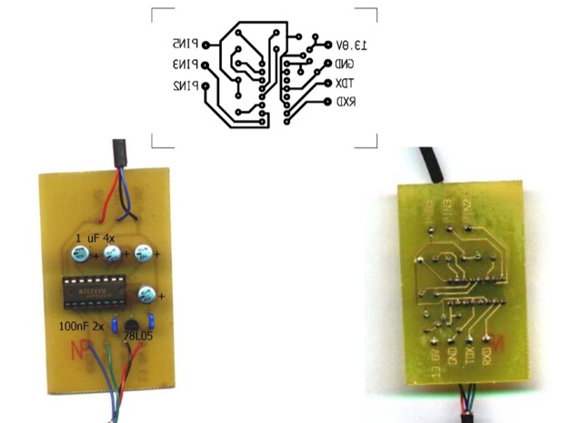
 Amateur Packet Reporting System (APRS) operations often require compact, reliable solutions for transmitting position data, particularly for mobile or portable stations. This resource details the construction of the _Tiny Track-I_, a transmit-only APRS tracker designed for straightforward integration with a VHF radio and a Global Positioning System (GPS) receiver. It enables hams to broadcast their location without the complexity of a full-duplex TNC. The project outlines the printed circuit board (PCB) layout and schematic, based on an original design by N6BG, with a personal PCB drawing by SV1BSX. It includes specific component placement and notes an additional 10uF/10V capacitor (C5) for improved IC voltage decoupling, a modification not present in the original N6BG diagram. The unit connects to a computer or GPS via a DB9 female connector. This tracker is ideal for basic position reporting, offering a simple and effective way to participate in APRS networks. Its small footprint makes it suitable for vehicle installations or field deployments where space is limited, providing a **reliable 9600 baud** data stream for location updates.
 -
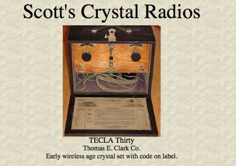 The TECLA Thirty, an early wireless age crystal set, is featured among a gallery of over 100 collectible headphones, with detailed close-up photos of vintage models. Several pages offer vintage headphones for sale, including Brandes, Baldwin, and Western Electric, suitable for crystal set use or collecting. Construction details are provided for a reproduction KILBOURNE AND CLARKE crystal set, built with vintage 1920s parts and featuring a miniature variable condenser for fine tuning. The resource also presents a project for a simple crystal radio and a 1-tube amplifier, complete with a schematic and component diagram, suitable for driving a horn speaker or amplifying weak signals for headphones. Instructions for mounting argentiferous galena detector crystals are included, along with information on MRL Handbooks covering crystal detectors and modern diodes. Additional projects include a 2A3 single-ended triode tube amplifier and two stereo tube amps using 12AX7, 6V6, 5Y3G, 6SN7, VT-25, and 5U4G tubes.
 -
 This page describes a comparison study on seven different beam antennas for 40 meters band. Yagi antennas, moxon antennas, mini horse all antennas are described with schema diagram , azimuth plot and SWR F/B Gain diagram
 -
 Adapting a common PC earphone with microphone to connect to a transceiver via a homemade pre-amplifier, using a simple chip with aprox 10 db gain. Includes a schematic diagram
 -
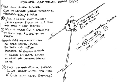 Schematic drawing and instructions for the construction of a simple portable dipole for use in low power and portable operations
 -
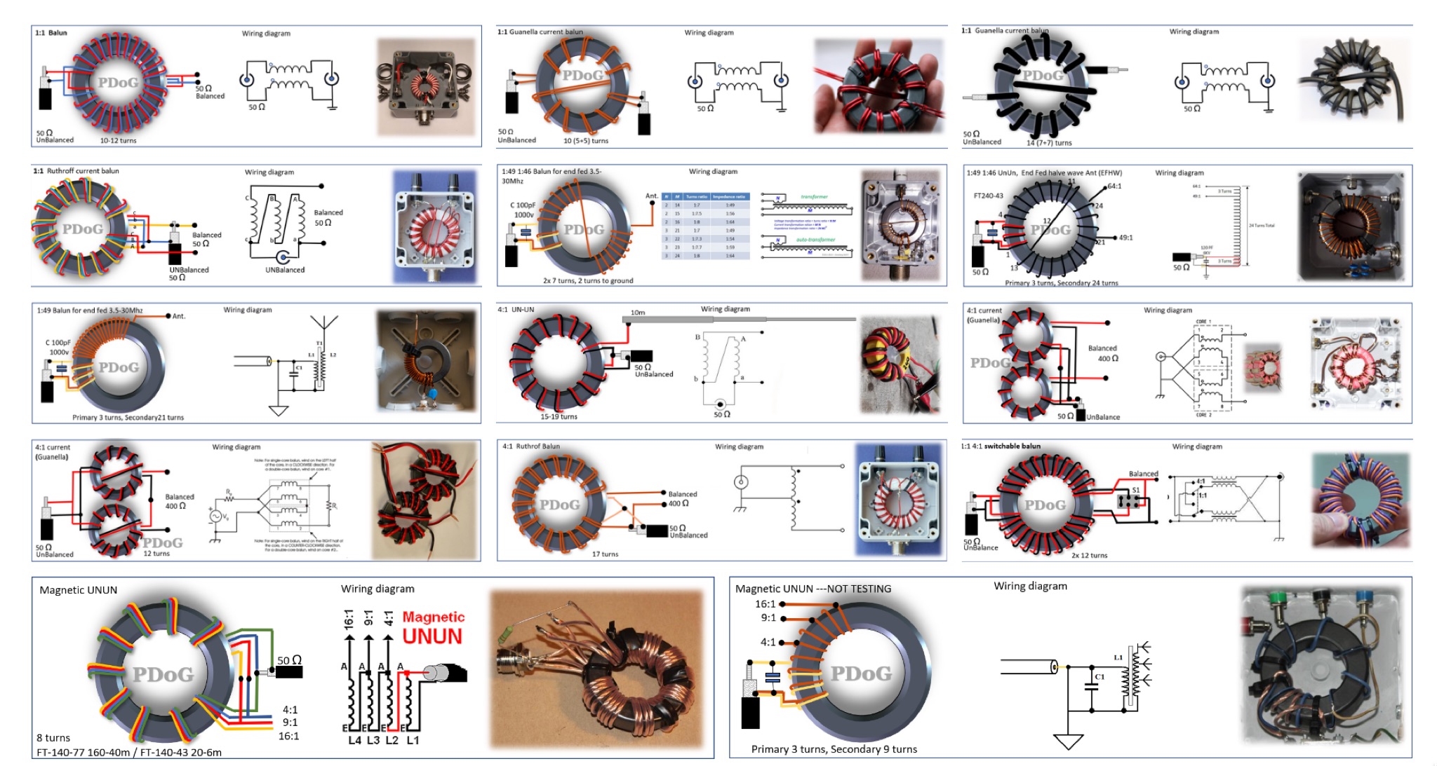 This page provides a detailed guide on the Guanella Current Balun for ham radio operators. The author shares very nice schematics, photos, and explanations on the construction and use of this type of balun. The content explains when a balun is needed and how it can help with common-mode currents in antenna systems. It also discusses the construction process, including winding the balun around a ferrite core. This resource is useful for hams looking to improve their antenna systems and reduce common-mode currents for better performance. This article is in Dutch.
 -
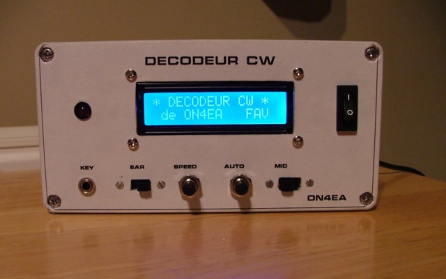 A homemade morse code decoder project, providing a detailed schematic and pictures
 -
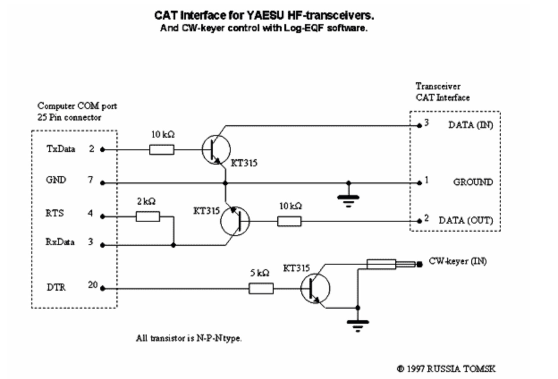 Schematic diagram circuit to build a RS232 serial interface for the Yaesu FT 1000D, works also as CW Keyer control with Log-EQF software. May be used with other Yaesu HF Transceivers.
 -
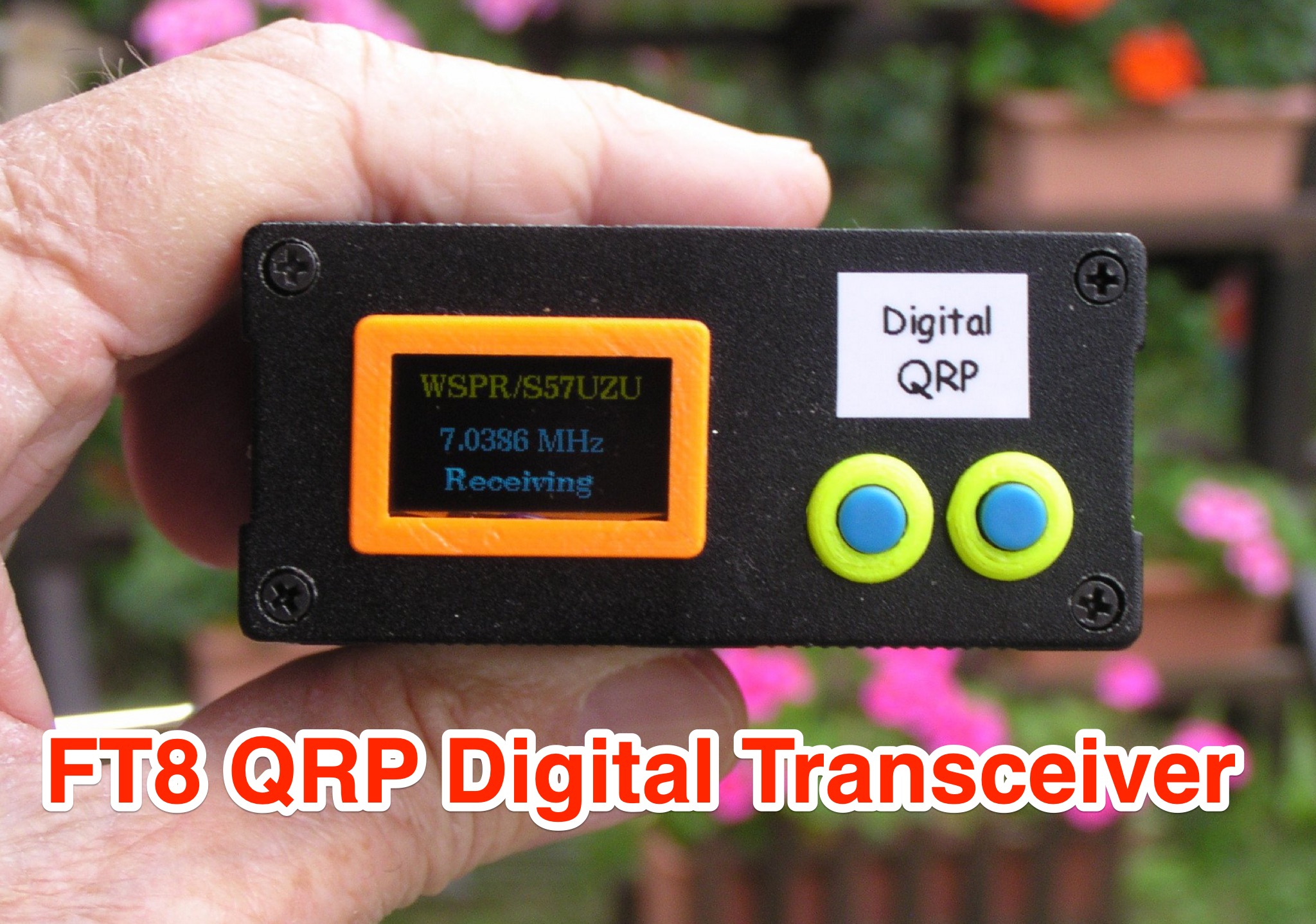 Learn how to build a QRP digital transceiver with Arduino, based on a project by Burkhard Kainka. This article covers the development process, including the source code, modifications made, and the addition of an OLED display for a more professional look. Discover the inner workings of the transceiver, from the receiver to the oscillator, and how components like the CD2003 are utilized. Explore the schematic design, the use of a PLL module Si5351A controlled by Arduino nano, and more. Ideal for hams looking to create their own digital transceiver for amateur radio operations.
 -
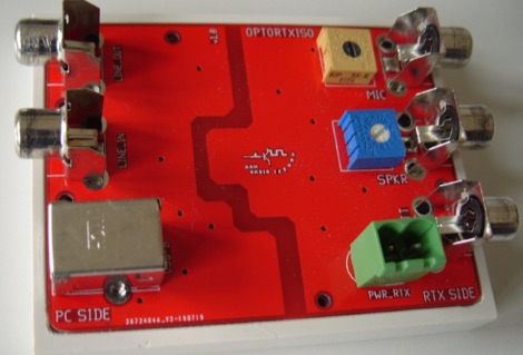 An optocoupled audio interface between PC and Transceiver for digital modes. The article includes full schematic of complete board and build instructions.
 -
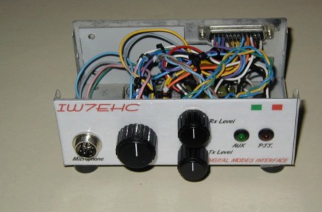 The use of an isolation interface between the radio and the pc is higly recommended,in order to avoid the problems that could be caused from ground loops. This project includes schematic and assembly instructions
 -
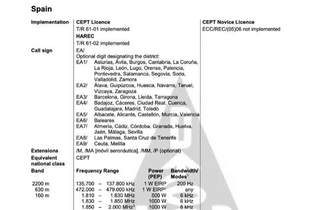 A document that includes a list of all countries implementing CEPT licence, with detailed information on licence types like standard CEPT, CEPT Novice and HAREC. A full list of frequencies, and call signs schemas to be used by foreign operators, compiled by Hans Schwarz, DK5JI
 -
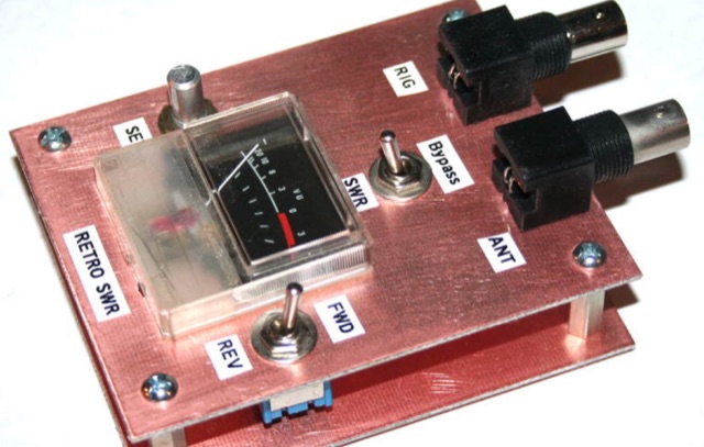 Analysis, design and construction of a simple & useful SWR meter from yesteryear! Schematic diagram, pictures and instructions to build a Monimatch style SWR Meter
 -
 This project revisits a minimalist software-defined radio (SDR) receiver built using a Raspberry Pi Pico, now optimized for simplicity and affordability. Designed for breadboard assembly with through-hole components, the receiver covers 0–30MHz, supporting CW, SSB, AM, and FM modes with an OLED display and spectrum scope. Key improvements include enhanced frequency accuracy, reduced op-amp saturation, and lower-cost components. Powered by three AAA batteries, it delivers standalone operation for global signal reception. Ideal for hobbyists, the design fosters experimentation and is documented with firmware and schematics available online.
 -
 Home made 40 meter transceiver project. The receiver is a Progressive Receiver with a few modifications. The Transmitter is a modified MFJ Cub circuit. Includes schematic and circuit diagrams for Receive Input Filter, 3-Pole 500 Hz Cohn Filter and 7 MHz Double Tuned Bandpass Filter
 -
 Schemaric diagram for a 80m, 40m, 30m, 20m EFHW Antenna Antenna Tuner. The tuner has been designed for an antenna length of 41m and the counterpoise 7.5m.
 -
 Paul McMahon presents a compact VSWR meter designed for QRP portable use, ideal for SOTA operations with rigs like the FT817. The device, constructed from readily available components, employs a simple resistive bridge for wideband performance from 1.8MHz to 52MHz, with diminishing accuracy at higher frequencies. Key features include no need for external power, simple calibration, and operation with low power levels. The design, detailed with parts lists, schematics, and construction guidelines, ensures a 2:1 worst-case VSWR to protect transceivers during antenna matching. Calibration points are set for accurate VSWR readings at various loads.
 -
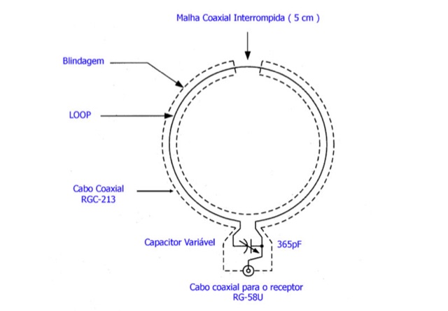 This page is a project for a small loop antenna for reception of short wave broadcasting. It is in Portuguese and contains pictures and schematics to build your own antenna
 -
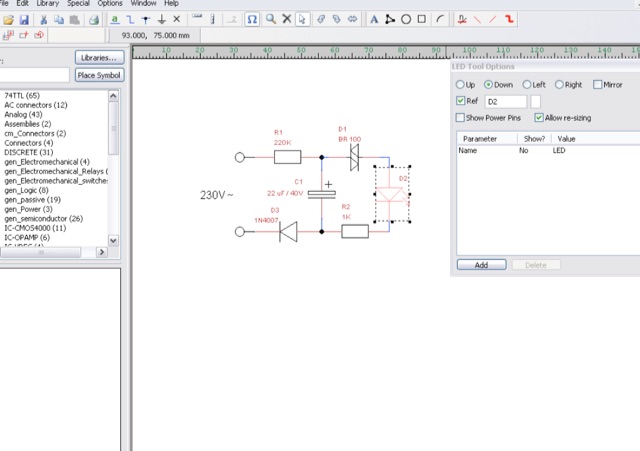 TinyCAD is a an open source program for drawing circuit diagrams which runs under Windows. TinyCAD is a program for drawing electrical circuit diagrams commonly known as schematic drawings. It supports standard and custom symbol libraries. It supports PCB layout programs with several netlist formats and can also produce SPICE simulation netlists.
 -
 Build your own 3-IC Iambic Electronic Keyer. Here, you will find schematics and operation descriptions. Includes Dot/Dash Memory, Progressive Element Weighting
 -
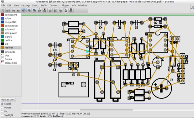 PCB is an interactive printed circuit board editor for Unix, Linux, Windows, and Mac systems. This Software runs across multiple platforms such as Unix, Linux, Windows as well as Mac systems. This Tool is widely used for electronics as well as electrical circuit designing that comes with schematic capture. PCB offers high end features such as an autorouter and trace optimizer which can tremendously reduce layout time.
 -
 Homemade custom CAT interface cable for the Yaesu FT-817 this article include schematics diagram for the interface and some pictures
 -
 The 222 MHz Transverter project, based on Zack Lau's (W1VT) original July 1993 QEX magazine design, provides an IF of 28 MHz for both transmit and receive paths. Rick Bandla (VE3CVG) contributed supplemental notes and construction details, including modifications to achieve 10 mW output power from an initial 4 mW PEP. The design incorporates three distinct boards: a Local Oscillator (LO), a Transmitter (Tx), and a Receiver (Rx), with an estimated parts cost of just over $150 CDN, significantly less than commercial kits. Construction involves both through-hole and surface-mount components, with specific guidance on mounting MAV and MAR devices, grounding techniques, and component selection. The project details include parts lists, schematics for the LO, Tx, and Rx, and board layouts. Troubleshooting advice emphasizes sequential testing, starting with the LO, then Tx, and finally Rx, using a 194 MHz and 222.100 MHz capable FM handheld for signal tracing. Further enhancements are discussed, such as an optional Tx driver stage to boost output to 100 mW and the potential modification of a Motorola Maxor 80 PA for 222 MHz SSB/CW operation. The resource also covers practical aspects like power attenuation pads for IF radios (e.g., FT817) and considerations for enclosure design, including repurposing a Maxor 80 case. Performance reports indicate successful 70 km contacts with only 4 mW output.
 -
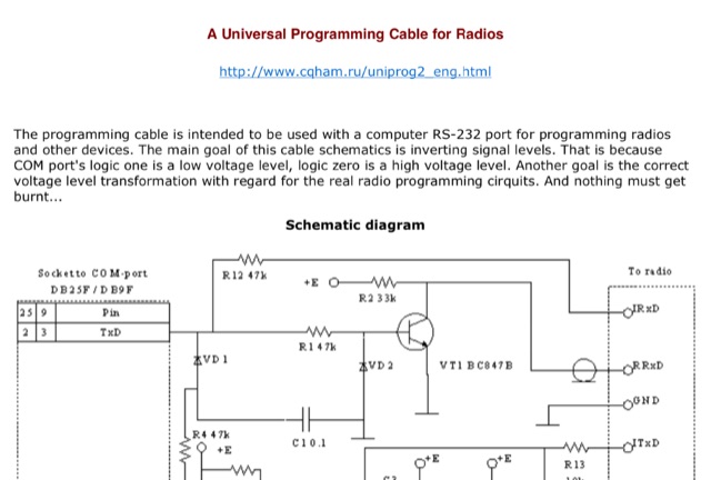 The programming cable is intended to be used with a computer RS-232 port for programming radios and other devices. The main goal of this cable schematics is inverting signal levels.
 -
 This is a power amplifier project for a RF 600W 1.8 MHz to 70 MHz linear amplifier including a Low Pass Filter. Projects includes schematics, pictures, PCD design, fans details, note on PA ferrite chokes and assembling instructions
 -
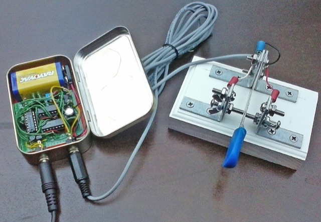
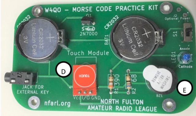 The Code Practice Oscillator kit, featured at TechFest 2020, provides a straightforward device for Morse Code skill development. It utilizes two 3V coin batteries for power and is designed for ease of construction, making it accessible for hams of various ages. The kit's primary technical substance revolves around generating an audible tone for practicing Morse Code timing and ear training, with a downloadable schematic detailing its electronic configuration. Construction of the oscillator involves soldering, with adult supervision recommended for younger builders. The kit's practical application lies in offering a hands-on method for beginners to learn Morse Code and for experienced operators to refine their sending abilities. Instructions for assembly are available as a downloadable PDF, complementing the schematic to guide users through the building process.
 -
 Presents a detailed construction guide for a 9 dB, 70cm collinear antenna, utilizing readily available _RG58/U_ coaxial cable and PVC pipe for housing. The resource outlines the critical calculations for ½ wavelength sections at 444 MHz, incorporating the coaxial cable's velocity factor of 0.66, which yields a section length of 223 millimeters. It specifies the preparation and soldering of eight such half-wavelength sections, each cut to 231mm to allow for trimming, forming the core of the array. Further instructions detail the integration of a ¼ wave element (169mm #16 solid wire) at the top and a ¼ wave aluminum tube (160mm, 5/16 inch) at the bottom, crimped to the feed point's braid. The guide also addresses RF common mode current suppression by suggesting the use of _FT50-43_ toroids on the feedline. Final assembly steps cover mounting the antenna within ¾" PVC pipe using a wooden dowel, waterproofing connections, and initial SWR checks. The article also discusses scaling the design for different element counts and other VHF/UHF bands.
 -
 This is a plan for an optimized element UHF Yagi Antenna for UHF Bands featuring a 9dBd forward gain, a 13 dB front-back ratio, and a bandwith of 10 MHz on the 430-440MHz range.
 -
 A Cross Platform and Open Source Electronics Design Automation Suite that runs on multiple operative systems. It allow to easily create even complex schematics and is suitable for professional use