Search results
Query: ss meter
Links: 566 | Categories: 3
-
 Manufacturer of single band and multiband transceiver bandpass filters for HF. High pass filters, two radoi headphones mix and switch, 6 meter portable antenna, antenna remote switching and steering.
 -
 Accurately determining an antenna's feedpoint impedance is crucial for optimal performance, especially when experimenting with new designs or making adjustments. While SWR meters provide basic information, a full complex impedance measurement reveals the resistive and reactive components, which are essential for proper matching. Modern antenna analyzers, like the _Palstar ZM30_ or MFJ259B, simplify this task, but measurements taken through a transmission line require careful interpretation due to impedance transformation. This resource details a calibration method to precisely account for the effects of the feedline. It explains how a transmission line can significantly alter the measured impedance, illustrating this phenomenon with a Smith Chart example where an 80m antenna's [22 + j6] Ohms feedpoint impedance transforms to [82 + j45] Ohms after a 10m line. The guide demonstrates using a transmission line calculator applet, such as the one by W9CF, to reverse this transformation. It outlines the process of calibrating a specific length of RG174 coax, showing how an initial 26ft estimate was refined to **25.85ft** to accurately predict a known 22 Ohm load, significantly improving accuracy over uncalibrated results.
 -
 DX_Central, a compact desktop application, provides amateur radio operators with critical propagation data by aggregating solar statistics and imagery from various authoritative sources. This includes real-time information from agencies like NOAA and NIST, offering insights into current space weather conditions that directly impact HF propagation. The software is designed for both Linux and Windows operating systems, making it accessible to a broad range of hams. It presents a concise overview of solar activity, which is essential for planning DX operations and understanding band openings and closures across the HF spectrum. Operators can utilize the displayed solar flux index, K-index, and other relevant parameters to make informed decisions regarding their operating times and target bands, optimizing their chances for successful long-distance contacts.
 -
 Ham Radio Kits, morse keyers, Morse code voltmeter / DC switch / battery saver
 -
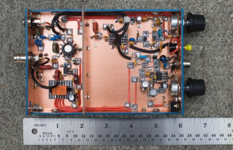
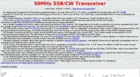 A SSB CW transceiver for six meters band with schematic and block diagram
 -
 The YB7ZGP Pamaton Repeater operates on a frequency of 146.76 MHz, serving the Martapura District in Banjar, South Kalimantan, Indonesia. This VHF repeater provides local communication infrastructure for amateur radio operators in the region. The repeater's operation is managed by Syah Riyan, indicating a local amateur radio enthusiast or group maintains the station. Repeaters like YB7ZGP are critical for extending the range of VHF/UHF communications, allowing handheld and mobile transceivers to communicate over greater distances than line-of-sight. The 146.76 MHz frequency falls within the 2-meter band, a popular segment for local and regional amateur radio traffic, often utilized for emergency communications and general ragchewing. Information regarding the _Pamaton Repeater_ is presented on a blog platform, suggesting a community-driven effort to disseminate details about this local amateur radio asset.
 -
 2 Meter Indoor Slim Jim Antennas for Cyclone Season and Other Uses by VK4MDX
 -
 A 40 meter rig with SSB and CW operating modes. This is a low power QRP rig with up to 6 watts CW or PEP output.
 -
 Cushcraft X7 20-15-10 Meter 7 element beam Assembly & Installation
 -
 Optimizing a G5RV or ZS6BKW multiband wire antenna for HF operation often involves addressing common SWR issues and understanding feedline characteristics. This resource chronicles the construction and performance evaluation of a G5RV, initially built for 80m, 40m, 15m, and 10m bands, by a newly licensed Foundation operator. The author details the selection of materials, including 3.5 mm stainless steel wire for the doublet arms and enameled copper wire for the open-wire feeder, and the initial decision to omit a balun based on common online information. The narrative highlights the initial disappointing performance, characterized by high receive noise and poor signal reports on 80 meters, despite the transceiver's internal ATU achieving a 1:1 match. This led to experimentation with a coax current balun and further research into G5RV myths, such as SWR claims and the necessity of a balun. The author then describes modifying the antenna to the ZS6BKW configuration, which involves specific changes to the doublet and feedline lengths, and integrating a 1:1 current balun wound on a ferrite toroid. The modifications resulted in improved reception and transmit performance across the bands.
 -
 Details the Northern Amateur Relay Council of California (NARCC) as the regional coordinating body for amateur radio repeaters operating on the 10-meter band and above. It outlines NARCC's function in managing frequency allocations to minimize interference and ensure efficient spectrum use across Northern California. The resource specifies that NARCC operates in cooperation with the FCC and ARRL, indicating its recognized authority within the amateur radio community. The organization's role centers on repeater coordination, a critical aspect of VHF/UHF operations where multiple stations share limited frequency segments. It highlights the support received from local amateur radio operators, underscoring a community-driven approach to spectrum management. The site serves as a primary reference for hams seeking to establish or operate repeaters within the designated service area. NARCC's activities directly impact the operational landscape for _VHF_ and _UHF_ enthusiasts, providing essential guidelines and coordinated frequencies. This ensures orderly communication and prevents conflicts, particularly in densely populated areas of Northern California.
 -
 For amateur radio operators engaged in **radio direction finding** (RDF) and **transmitter hunting** (T-hunting) activities, this resource provides a catalog of printed circuit boards (PCBs) for constructing various DF and foxhunt-related projects. The offerings include PCBs for 80-meter fox transmitters and receivers, UHF fox transmitters with audio recording capabilities, and several designs for general-purpose radio direction finders. Specific projects like the "Simple 80M ATX-80 Transmitter" and the "N0GSG DSP Radio Direction Finder" are listed, along with attenuator boxes and specialized components for Doppler DF systems. The catalog details PCBs for projects published in prominent amateur radio magazines such as *73's*, *CQ*, *QST*, and *PE*, indicating their origin and design pedigree. For instance, the "Montreal Fox Controller" is sourced from the *Homing-In* column by Joe Moell, K0OV. The resource also lists components for advanced Doppler DF systems, including main boards, LED display boards, and antenna switch boards, with options for programmed PIC microcontrollers. Pricing for each PCB is provided, allowing hams to acquire the necessary components for their DIY RDF endeavors.
 -
 Demonstrates the construction of a 144 MHz turnstile antenna, detailing its design for omnidirectional, horizontally polarized VHF operation. The resource outlines the physical dimensions and materials required, including specific lengths for the radiating elements and the use of _RG-58_ coaxial cable for phasing. It covers the assembly process, emphasizing the critical spacing and connection points to achieve the desired radiation pattern and impedance matching for the _2-meter band_. The article presents measured _SWR_ performance across the 144-146 MHz segment, showing a low SWR of 1.2:1 at 144.5 MHz, which is suitable for general VHF use. It compares the turnstile's performance to a 9-element Yagi, noting the turnstile's advantage in providing consistent signal strength from all directions without requiring a rotator. Practical application for local FM simplex and repeater operations is implied, offering a simple yet effective antenna solution for fixed or portable stations.
 -
 US Antenna manufacturer offering base and mobile antennas for 2 meter, 1.25 meter and 70 cm Amateur Radio GMRS and MURS Citizens Band Radio VHF and UHF Business Band Radio HF, VHF and UHF Scanning
 -
 Crystal-controlled QRP tranceiver by F6BCU for 80 meters band 1W output
 -
 The resource presents a detailed schematic for constructing a dual-band vertical antenna, specifically designed for operation on the 2-meter and 70-centimeter amateur radio bands. It illustrates the physical layout, critical dimensions, and component placement necessary for successful replication. Key elements such as the radiating elements, phasing sections, and feed point are clearly depicted, providing a visual guide for radio amateurs undertaking a homebrew antenna project. The diagram specifies the lengths for the VHF and UHF sections, indicating how these elements are integrated to achieve dual-band functionality from a single coaxial feedline. It also implies the use of common materials readily available to most experimenters, focusing on simplicity and effectiveness in its design. The visual format of a GIF image ensures direct access to the construction details without requiring extensive textual interpretation. This schematic serves as a practical reference for hams interested in building a compact, efficient vertical antenna for local and regional FM communications, offering a proven design for immediate implementation.
 -
 Presents a QRP AM/CW transmitter project specifically designed for the 10-meter band, utilizing a crystal oscillator and a collector-modulated AM oscillator. The design employs a 2N2219(A) transistor in a Colpitts configuration, generating 100 to 350 mW of RF output power depending on the 9-18 Volt supply voltage and modulation depth. Frequency stability is maintained by a 28 MHz crystal, with fine-tuning possible via a Ct1 trimmer capacitor for approximately 1 kHz adjustment. The resource details the RF oscillator stage, implemented with a 2N2219 NPN transistor, emphasizing frequency stability and low power dissipation. It also covers the amplitude modulation stage, managed by a 2N2905 PNP transistor, which impresses audio information onto the carrier. Selective components (C3, C4, C7, C5) enhance voice frequencies within a +/- 5 kHz bandwidth, and modulation depth is controlled by R2 and R3. The project includes a 3-element L-type narrow bandpass filter (Ct3, L3, C10) to suppress harmonics and ensure a clean output signal. The project provides a complete schematic diagram, a comprehensive parts list including specific capacitor, resistor, and inductor values, and construction notes for the coils (L1, L2, L3). It also offers practical advice on enclosure requirements, suggesting an all-metal case or a PVC box with graphite paint for RF shielding. Operational parameters such as current draw (27mA@9V to 45mA@16V) and input impedance (50 Ohms) are specified, alongside guidance on antenna matching and the importance of a valid amateur radio license for 10-meter band operation.
 -
 The antenna build into this project is made from 2 fishing poles on a fiberglass pole in the center.
 -
 The ZS6BKW multiband antenna, an optimized variant of the classic G5RV, features a 102-foot (31.1 m) horizontal span and a 39.1-foot ladder line matching section. This design, derived by G0GSF (formerly ZS6BKW) in the early 1980s using computer programs and _Smith charts_, aims for improved SWR across multiple HF bands compared to its predecessor. Construction details specify Wireman 554 ladder line and #14 AWG THHN copper wire for the radiators, with precise instructions for determining the velocity factor (VF) of the ladder line using an antenna analyzer or dip meter, ensuring accurate physical length for the matching section. The radiator length is electrically 1.35 wavelengths for the 20-meter band, requiring careful trimming during tuning. Field measurements with an _AIM-4170C_ analyzer by KI4PMI and NC4FB demonstrated good SWR curves and bandwidth on 6, 10, 12, 17, 20, and 40 meters. The antenna was deemed unusable on 15 and 30 meters due to very high SWR, but an LDG AT-100PRO autotuner successfully brought 6 and 80 meters into tune. Contacts were made on 80, 40, 20, and 17 meters, including a **17-meter** contact to Spain. EZNEC models for 80-6 meters are provided, along with an AutoEZ model by AC6LA, which predicted good SWR for 80-10 meters. W5DXP's modifications for an all-band HF ZS6BKW are also referenced.
 -
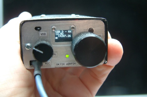 The Micro24 is a ultra compact microsize QRP SSB transceiver for the 20 meters amateur radio band. This transceiver is so small that it fits into one hand.
 -
 A two meter Quad antenna project with detailed instructions on how to adjust the Quad gamma match
 -
 Bird wattmeters and extras accessories
 -
 A very efficient 80 meter Counterpoise antenna designed to reduce ground losses from inadequate radial systems beneath inverted L antennas, a project by DM2GM and DM4IM based on the original K2AV antenna concept.
 -
 Demonstrates the construction and implementation of a **two-element phased vertical array** for 40 meters, utilizing _Christman phasing_ techniques. The author, W4NFR, details the process from building individual 1/4-wave aluminum verticals to integrating them into a phased system. The resource covers antenna spacing of 32 feet, elevated radial design, and the critical steps for tuning each vertical to achieve a 1.1:1 SWR before combining them. It also provides insights into calculating precise coax lengths for feedlines and the phasing delay line, emphasizing the use of an MFJ-269 Antenna Analyzer for verification. The finished system exhibits good front-to-back nulls, with an overall SWR ranging from 1.6:1 to 2.2:1, which is managed by an antenna tuner. The project includes detailed photos of the relay box, showing 12 VDC relays capable of handling 5KV, and the control box in the shack for switching between three different antenna pattern configurations. Static bleed-off chokes are incorporated for protection, and the construction emphasizes robust weatherproofing for outdoor elements.
 -
 Summary of discussion on stacking antennas on six meter band
 -
 This project details the construction of a **full-sized 40-meter vertical antenna**, born from a renewed interest in 7 MHz operation and a desire for improved effectiveness over simple dipoles. The author, K5DKZ, initially focused on VHF experimentation, which provided an inventory of aluminum tubing and fiberglass spreaders for this endeavor. Before this vertical, K5DKZ utilized an 80/40 meter inverted-vee trap dipole and a 40-meter broadband dipole, but now primarily uses a pair of full-sized, phased, quarter-wave verticals spaced 35 feet apart for serious 40-meter work. The construction involves a base-heavy design for stability, using a 44.5-inch section of 1-1/4 inch steel TV mast driven into 1-3/8 inch aluminum tubing, insulated by a 105-inch section of Schedule 40 PVC pipe. The assembly reaches 31 feet, close to the 32 feet required for a quarter-wavelength on 40 meters, with fine-tuning achieved by winding wire onto a fiberglass spreader. The design is explicitly presented as a foundation for a two-element 40-meter Yagi beam, outlining modifications like substituting aluminum for steel in the base and using an inductive hairpin match for the driven element. The article also discusses tuning considerations for a large 40-meter beam, noting the 100 to 200 kHz upward frequency shift when raised, and suggesting methods for installation on a tower. The author emphasizes the cost-effectiveness and good performance of the monopole approach, especially when multiple verticals are needed.
 -
 A fractional bandwidth of up to 30:1 characterizes spiral antennas, making them highly effective across a very wide frequency range, often from 1 GHz to 30 GHz. The resource details two primary types: the **Log-Periodic Spiral Antenna** and the **Archimedean Spiral Antenna**, defining each with specific polar functions and illustrating their planar configurations. It explains that spiral antennas are typically circularly polarized, with a Half-Power Beamwidth (HPBW) of approximately 70-90 degrees, and a peak radiation direction perpendicular to the spiral plane. The content elaborates on critical design parameters affecting radiation, including the total length (outer radius) for lowest frequency, the flare rate ('a' constant) for optimal radiation versus capacitive behavior, the feed structure (often an infinite balun) for high-frequency operation, and the number of turns (typically 1.5 to 3 turns). It also discusses the theoretical impedance of 188 Ohms for Log-Periodic spirals, derived from Babinet's Principle, noting actual impedances are often 100-150 Ohms. The article presents a simple construction method for an Archimedean spiral, demonstrating VSWR and efficiency measurements. Measurements from a constructed spiral antenna show a VSWR that is fairly constant across the band, albeit with a mismatch loss of about 3 dB. The antenna efficiency remains around -5 dB (31.6%) across its operating range, indicating a decent wideband radiator despite opportunities for optimization.
 -
 The Yaesu VX-5R, manufactured between 199x and 200x, offers a transmit frequency range covering 50-52 MHz, 144-146 MHz, and 430-440 MHz for European models, with US versions extending to 50-54 MHz, 144-148 MHz, and 430-450 MHz. Its receiver boasts an impressive wideband capability from 0.5 MHz to 999 MHz, with cellular frequencies blocked in some regions. The unit provides up to 5 watts RF output on 6 meters and 2 meters, and 4.5 watts on 70 centimeters, with selectable lower power settings down to 300 mW. This handheld transceiver utilizes a double conversion superheterodyne receiver system, featuring a 47.25 MHz first IF for FM and 45.8 MHz for WFM. Key specifications include a frequency stability of ±5 ppm across a wide temperature range and a current drain of 25-150 mA on receive. The VX-5R supports 220 regular memory channels with alpha tags, 3 home channels, and 10 NOAA weather channels, all stored in non-volatile EEPROM. Additional features include CTCSS/PL and DCS with tone search, ARS, ARTS, an internal voltmeter, and a Spectra-Scope. The device operates on a 7.2 VDC battery pack or 10-16 VDC external power, weighing 255 grams with dimensions of 58x88x27 mm. The VX-5R was also available as the metallic silver VX-5RS.
 -
 Showcasing a specialized product line, Advanced Receiver Research presents a comprehensive catalog of **low noise preamplifiers** and microwave **Gunnplexers**. The offerings span a broad spectrum of radio frequencies, from VLF, LF, MF, and HF bands up through VHF, UHF, and microwave, catering to diverse applications including amateur radio, commercial installations, and military systems. Their product range includes mast-mount preamplifiers, inline attenuators, power dividers, and various coaxial components. My own experience with similar low-noise front ends for weak-signal work on 2 meters and 70 centimeters underscores the critical role such components play in maximizing receiver sensitivity, especially when chasing distant DX or engaging in EME. The detailed product descriptions and technical specifications provided on the site allow operators to select the optimal preamplifier for their specific band and noise figure requirements, essential for improving signal-to-noise ratio. The site also lists specialized products for unique applications like Nuclear Magnetic Resonance (NMR) and Studio Transmitter Links (STL), demonstrating a depth of engineering capability beyond typical amateur radio fare. This breadth of offerings, coupled with clear ordering and warranty information, positions Advanced Receiver Research as a key supplier for high-performance RF components.
 -
 Operating on the 11-meter band, the Alfa Tango Argentina website serves as a digital hub for CB radio DX enthusiasts, particularly those affiliated with the _Alfa Tango_ international group. The resource primarily functions as a community portal, facilitating connections among members and promoting activities related to long-distance CB communications. It presents basic information about the group's presence in Argentina and emphasizes the social aspect of radio communication, framing participants as "friends who have never met." The site's content reflects the operational focus on **DXing** within the CB radio sphere, a practice that mirrors amateur radio's pursuit of distant contacts. While specific operational data or technical guides are not detailed, the site's existence supports the organizational structure of the Alfa Tango group, which coordinates activities across various countries.
 -
 This document details the design and construction of the PA70H, a 50-watt RF amplifier for the 70MHz (4-meter) amateur radio band. Built around the Mitsubishi RD70HVF1 MOSFET transistor, the amplifier delivers 45-55W output with 3-5W input power while operating on 13.8V DC at approximately 7-8A. The PCB design incorporates multiple protection circuits including overcurrent, SWR, and temperature control. The amplifier features various control modes including GND PTT, +13.8V PTT, and RF VOX. Two versions are available: PA70HLI (requiring 100mW input with additional driver) and PA70H (for 3-5W input). The comprehensive documentation includes circuit diagrams, assembly instructions, and performance data showing successful operation from both 100mW and 3.5W input sources.
 -
 A moxon antenna project made with wires and fiberglass poles
 -
 Examines the Icom IC-2100H 2-meter mobile transceiver, detailing its operational characteristics and user experience. The review highlights the clear, easy-to-read display with internal labels, the button-filled microphone's functionality, and the rig's physical construction, including its weighty heat-sink and lack of a cooling fan. It also discusses memory programming, the unique amber-to-green backlight color options, and the radio's performance against _intermodulation_ in urban environments, noting it performs "pretty darn good" compared to other rigs. The analysis delves into a significant low-voltage cutoff problem, where the microphone ceases to function below approximately **12.6 VDC**, rendering the radio receive-only or causing it to stick in transmit. The author describes testing the voltage cutoff, observing it fluctuate from _12.38 VDC_ to 12.69 VDC. An update from Icom involved a "factory update" to the CPU's control code, which is strongly recommended for early-serial number units to prevent operational failure in low-power emergency scenarios.
 -
 Demonstrates the adaptation and construction of a 7-element DK7ZB Yagi antenna for the 4-meter band (70 MHz), utilizing components from a defunct 2-meter CUE DEE Yagi. The resource details the modifications made to the original DK7ZB design to fit the shorter CUE DEE boom length, specifically adjusting element lengths for 6mm rod elements while reusing existing mounting holes for the reflector and last director. It provides precise element lengths for the reflector, dipole (12mm aluminum tube), and five directors, along with a note on cutting elements for transport. The article includes a 4NEC2 simulation file for performance analysis and an SWR plot, confirming the antenna's electrical characteristics. It also specifies the calculation for the quarter-wavelength matching cable using SAT752F coaxial cable, resulting in a 909mm length. Practical application is shown with the finished antenna in operation at JO20XC, listing several activated Maidenhead squares such as JO56PA and JP40KS, validating its effectiveness for portable 70 MHz operations.
 -
 This PDF document details the construction of a **70 MHz** Big Wheel antenna, a horizontally polarized omnidirectional array. The design utilizes three full-wave loops, each approximately **2160 mm** in diameter, arranged in a triangular configuration. The resource provides mechanical dimensions for the antenna elements and a comprehensive bill of materials, specifying component quantities and types, such as M8 stainless steel bolts, 15x15x1.5 mm square aluminum tubing for spacers, and 8 mm aluminum rod for the arcs. The central hub is constructed from two 160x160x8 mm aluminum plates, with four 40 mm long polyamide insulators supporting the radiating elements. The feed system incorporates a 50 mm diameter aluminum pipe for mounting and a matching stub constructed from a 120x20x2 mm aluminum sheet, connected via M8x10 mm bolts. The resource includes a diagram illustrating the mechanical dimensions and assembly points, including the N-connector fixing point and the center conductor attachment. The project was published on May 25, 2011, by Peter OE5MPL and Rudi OE5VRL. DXZone Focus: PDF | 70 MHz Big Wheel | Mechanical Dimensions | **2160 mm** loop diameter
 -
 K0GKJ project of a copper tube slim jim antenna for two meter band
 -
 Cannot record CW message, AFSK not working, tracking not working, meter peak hold, on Yaesu FT-920.
 -
 Special test lead that converts your regular DC voltmeter to a RF reading voltmeter
 -
 The Receiver Test Data resource is a detailed review database focusing on the performance metrics of various radio receivers. The methodology involves rigorous lab measurements, often adhering to standards such as the ARRL RMDR (Reciprocal Mixing Dynamic Range) and BDR (Blocking Dynamic Range). Specific test equipment and protocols are utilized to assess parameters like noise floor (dBm), AGC threshold (uV), and LO noise (dBc/Hz). For example, the _Icom IC-7300_ is evaluated with a noise floor of **-133 dBm** and an LO noise of **-141 dBc/Hz**, providing insights into its performance under different operational conditions. The resource includes a wide range of models, from the _Elecraft K3S_ to the _Yaesu FTdx-101D_, each tested for dynamic range, sensitivity, and selectivity. The data is sorted by key metrics such as third-order dynamic range and phase noise limitations, with RMDR values calculated by subtracting 27 dB from LO noise figures. This structured approach allows users to compare different receivers' capabilities, focusing on technical specifications and performance outcomes in various scenarios. DXZone Focus: Review Database | Lab Measurements | -133 dBm | ARRL RMDR
 -
 A Co-ax Trap Dipole For 40, 30 and 20 Meters or at last that was the intention
 -
 The X80 multi-band HF vertical antenna, a commercial iteration of the Rybakov design, exhibits a physical length of 5.5 meters, or approximately 18 feet, and is constructed from aluminum tubing. It operates as a non-resonant vertical, requiring an external antenna tuner for impedance matching across its intended operating frequencies. The antenna's design incorporates a 1:4 UNUN at its base, facilitating a nominal 50-ohm feed point impedance for the coaxial cable. Performance observations indicate effective operation on 40 meters, 20 meters, 15 meters, and 10 meters, with reduced efficiency on 80 meters and 160 meters due to its relatively short electrical length for these lower bands. Comparative analysis with a G5RV dipole and a half-wave end-fed antenna reveals the X80 offers a lower take-off angle, beneficial for DX contacts, particularly on the higher HF bands. Field tests conducted with an Icom IC-706MKIIG transceiver and an LDG AT-100ProII autotuner demonstrate the X80's ability to achieve acceptable SWR across 80m through 10m. The antenna's compact footprint and ease of deployment make it suitable for restricted spaces or portable operations, though its performance on 80 meters is noted as a compromise compared to full-size resonant antennas.
 -
 The ZS6BKW multi-band antenna, an optimized variant of the classic G5RV, is presented with detailed construction and tuning instructions. This resource outlines the antenna's design principles, which were developed by _Brian Austin (G0GSF)_ using computer programs and Smith charts to achieve optimal dimensions. It provides specific guidance on calculating and adjusting the lengths of the radiators (L1) and the matching ladder line (L2), emphasizing the critical role of velocity factor (VF) in achieving resonance. The article includes a step-by-step procedure for empirically determining the VF of ladder line using an antenna analyzer, ensuring accurate physical lengths for the matching section. It details the tuning process for the radiators, offering practical tips for incremental adjustments to achieve the best SWR curve. The resource presents SWR measurement results obtained with an _AIM-4170C_ analyzer across multiple bands, alongside predicted SWR graphs from an AutoEZ model. It confirms successful contacts on 80, 40, 20, and 17 meters, including a **17-meter DX contact** to Italy. EZNEC and AutoEZ models for the ZS6BKW antenna, covering 80 through 6 meters, are provided for download, allowing further analysis and customization. The document specifies component details, such as the use of Wireman 554 ladder line and #14 AWG THHN copper wire, and discusses the antenna's performance characteristics, noting high SWR on 15 and 30 meters but successful tuning on 6 and 80 meters with an external tuner.
 -
 The resource details the construction of a homebrew 50-watt FET amplifier, based on Don W6JL's _QST Homebrew contest_-winning design from 2009. It functions as an afterburner for QRP transceivers, providing a **12dB** power lift. The amplifier utilizes IRFZ24N FETs and covers the 80, 40, 30, and 20-meter bands, with the 20m LPF extending to 17m. Key technical aspects include an FT37-43 transformer for the input network, a relay-switched 3dB pad for lower bands controlled by an _Arduino Nano_, and an RF-actuated T/R switch. The LPF board integrates four relay-switched filters rated for 50 watts, using capacitors with a minimum 250VDC rating. Performance measurements indicate a power gain ranging from **4.4dB** on 20m to 8.1dB on 80m, with a required drive power of approximately 5 watts. The article also discusses thermal management, current limiting considerations, and component sourcing.
 -
 A dipole antenna for 7 MHz support for this antenna is fiberglass military mast
 -
 Over 130 years after its inception, Morse Code remains a fundamental skill for many amateur radio operators, enabling efficient QRP operations, DXing, and contesting. This resource provides an in-depth look at the **Koch Method** of Morse training, a widely adopted technique that emphasizes high-speed character recognition from the outset. It details how this method can significantly accelerate proficiency, moving beyond traditional, slower learning approaches. The site also delves into the rich history of amateur radio, presenting articles such as "Radio on the Rio," which chronicles local ham activity in Socorro, New Mexico. Another piece, "The Russian Woodpecker," recounts the Cold War-era efforts of hams to counter Soviet over-the-horizon radar interference on the HF bands. Furthermore, the resource explores the fascinating intersection of ham radio and radio astronomy, highlighting the direct lineage between amateur experimentation and the development of modern radio telescopes like the **Very Large Array (VLA)**. It also includes an introduction to the 6-meter band, often called "The Magic Band," detailing its unique propagation characteristics and suitability for no-code licensees seeking long-distance contacts.
 -
 A hombrew QRP transceiver for 40 meter band with many pictures, circuit and sound recording of some QSOs made with this Rig consisting of 5 transistor and one chip.
 -
 Demonstrates various practical amateur radio projects and technical discussions through video episodes. One episode details cutting and retuning a _1/4 wave shorted stub_ from 101.7 MHz to 107.5 MHz to safeguard a transmitter's driver stage, alongside insights into advanced _160-meter antenna systems_ like eight-circle arrays and beverage antennas. Another segment covers upgrading firmware on an _ATS-20+_ receiver using AverDudes for improved display and functionality, and a detailed guide on using D-Star DR mode on an _ICOM ID-52A_ for international repeater programming. Additional content includes a deep dive into _OpenHamClock_ as a potential replacement for the HamClock project, updates on _Raspberry Pi 5_ running Trixie OS, and a review of the Choyong LC90 Internet radio with AI integration. The series also features "Ham College" episodes, which meticulously prepare viewers for the Technician Exam by covering topics such as antenna and transmission line measurements, SWR interpretation, and the functions of basic electronic components like rectifiers, relays, and transistors. Practical advice on coaxial cable characteristics, dummy loads, and proper soldering techniques is also provided.
 -
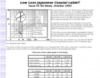 5D-FB,8D-FB,10D-FB cables offer very low attenuation comparable to that of famous Andrews' Heliax and 8D-FB is almost half that of standard RG-213 for an equivalent diameter!
 -
 Demonstrates the operational status and reception reports for the SK6RUD/SA6RR QRPP beacons, which transmit on 478.9 kHz, 1995 kHz, 10.131 MHz, and 40.673 MHz. These beacons utilize extremely low power, with the 630-meter beacon operating at approximately 0.1 watt ERP into an L-antenna, showcasing the potential for long-distance contacts under favorable propagation conditions. The site details the specific frequencies and antenna types employed, such as a vertical at 500 kHz and a 1/4 vertical for higher bands. The resource compiles over 10,530 reception reports from amateur radio operators worldwide, logging details such as date, time, band, RST signal report, locator, distance, and receiver setup. Notable long-distance reports include a 500 kHz reception by AA1A-Dave from 5832 km in 2008 and a 10.133 MHz reception by ZL2FT-Jason from 17680 km in 2010, illustrating the global reach of these low-power transmissions. Each log entry provides specific equipment used by the reporting station, including transceivers like the Yaesu FT817, ICOM IC-7300, and various antenna configurations such as coaxial mag loops, inverted Ls, and end-fed wires. The primary objective of the SK6RUD beacons is to challenge conventional notions of power requirements for effective two-way communication, proving that contacts over significant distances are achievable with minimal output. The site also includes a submission form for new reception reports, fostering community engagement and continuous data collection on propagation phenomena across different bands. The detailed logs offer practical insights into real-world propagation characteristics and the efficacy of QRPP operations.
 -
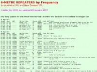 Presents a detailed compilation of **6-meter** voice repeaters operating within the 53-54 MHz segment across Australia (VK) and New Zealand (ZL), providing essential data for local and visiting radio amateurs. Each entry specifies the repeater's output and input frequencies, its assigned callsign (where applicable), the primary service area, current operational status (e.g., operational, under construction, scrapped), and a **Maidenhead grid locator**. The resource also includes the date the repeater was last heard or updated, offering insights into its recent activity. This listing is meticulously maintained by VK2KFJ, who updates entries based on personal observations and confirmed reports from other operators. It serves as a practical reference for hams seeking to utilize the 6-meter band for local communication via repeaters, particularly for those engaged in mobile or portable operations within the specified regions. The data helps operators configure their transceivers correctly for accessing these vital communication hubs. Beyond the repeater details, the page also notes common 6-meter FM voice simplex frequencies, such as the 52.525 MHz international call frequency, and lists historical packet simplex frequencies, though their current operational status is uncertain. This comprehensive approach ensures that operators have a broad overview of 6-meter activity in VK and ZL.