Search results
Query: amp
Links: 933 | Categories: 43
Categories
- Manufacturers > Amplifiers
- Technical Reference > Amplifiers
- Technical Reference > Amplifiers > HF Amplifiers
- Radio Equipment > HF Amplifiers
- Operating Modes > Morse code > High Speed CW > HST Championships
- Ham Radio > Clubs > North America > USA > New Hampshire
- Technical Reference > Preamplifiers
- Technical Reference > Amplifiers > RF Amplifiers Theory
- Operating Modes > Mobile > RV & Camping
- Technical Reference > Amplifiers > UHF Amplifiers
- Technical Reference > Amplifiers > VHF Amplifiers
- Radio Equipment > VHF-UHF Amplifiers
- Radio Equipment > HF Amplifiers > Acom 1000
- Radio Equipment > HF Amplifiers > Acom 1010
- Radio Equipment > HF Amplifiers > Alpha 8410
- Radio Equipment > HF Amplifiers > Alpha 87A
- Radio Equipment > HF Amplifiers > Alpha 9500
- Operating Modes > AM
- Radio Equipment > HF Amplifiers > Ameritron AL-80B
- Radio Equipment > HF Amplifiers > Ameritron AL-811
- Radio Equipment > HF Amplifiers > Ameritron AL-811H
- Radio Equipment > HF Amplifiers > Ameritron ALS-600
- Technical Reference > Audio
- Manufacturers > Broadcasting Equipment
- Ham Radio > Clubs > Europe > UK > Central England
- Radio Equipment > HF Transceivers > Elecraft K4
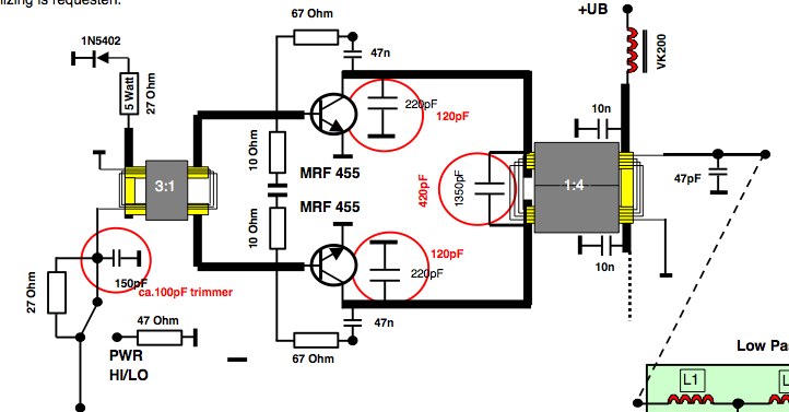
- Radio Equipment > HF Amplifiers > Heathkit SB-200
- Radio Equipment > HF Amplifiers > Heathkit SB-220
- Radio Equipment > HF Amplifiers > Kenwood TL-922
- Operating Aids > Log Formats
-
-
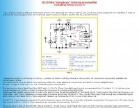 A simple & effective antenna pre-amp for 10m. Band (28-29.7 MHz)
 -
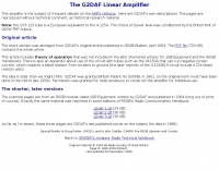 Scans of original G2DAF articles on his HF linear amplifier using QY3-125 tube
 -
 The ZS6BKW antenna, a popular multiband wire antenna, offers improved band matching compared to the traditional G5RV. This construction guide details the process, beginning with specific dimensions: 13.11 meters (43 feet) for the 450-ohm ladder line and initial dipole arm lengths of approximately 14.8 meters each. It emphasizes the critical role of an _antenna analyzer_ for accurate tuning, particularly for determining the velocity factor of the ladder line and achieving a 1:1 impedance match. The article outlines the materials required, including a 1:1 current balun, 450-ohm window line, wire for the dipole arms, and a 50-ohm non-inductive resistor for testing. It provides a step-by-step procedure for cutting the ladder line to its electrical half-wavelength, explaining how to calculate the velocity factor using measured and free-space frequencies. For instance, a measured 50-ohm impedance at 12.54 MHz with a calculated free-space half-wavelength frequency of 11.44 MHz yields a velocity factor of 0.91. Final adjustments involve hoisting the antenna to its operational height and fine-tuning the dipole arm lengths to achieve optimal SWR, specifically targeting 14.200 MHz. The _ZS6BKW_ design is noted for its performance on 80m, 40m, 20m, 10m, and 6m, though it is not optimized for 15m operation. The author, _VK4MDX_, shares practical tips for durable construction using stainless steel wire and cable clamps.
 -
 Power supplies, rf power amplifiers, dummy loads, frequency counters, repeaters antennas manufacturer based in Italy
 -
 This resource, "Transistor Audio Preamplifier Circuits," offers comprehensive design guidelines for constructing **bipolar transistor** audio preamplifiers. It delves into critical aspects such as quiescent current setting, voltage gain calculation, and the impact of various component choices on circuit performance. The content provides several _schematic diagrams_ illustrating different preamplifier configurations, including single-stage common emitter and two-stage designs, alongside explanations of their operational characteristics and practical implementation considerations. The analysis extends to frequency response, noise performance, and distortion, providing insights into optimizing these parameters for specific audio applications. The resource presents calculated gain figures for various stages, demonstrating how to achieve desired amplification levels. It also discusses the importance of proper power supply decoupling and input/output impedance matching, crucial for integrating these preamplifiers into larger audio systems or ham radio transceivers. The practical application of these designs is evident in their suitability for microphone preamplifiers or general-purpose audio amplification.
 -
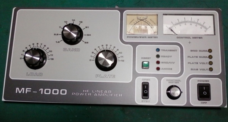 Topic regarding a new 1KW HF power amplifier with 2x GI7B
 -
 Whether we are tuning up homebrew equipment, checking antenna VSWR, adjusting a linear amplifier, or just monitoring output power during a contest, almost all aspects of ham operation can use a power meter. Paul Wade W1GHZ
 -
 Demonstrates the design and construction of a compact, portable multi-band mini-delta loop antenna, specifically optimized for /P (portable) operations from remote locations like Scottish islands. The resource covers the theoretical underpinnings of half-wave loops, contrasting closed and open configurations, and then details the application of a folded dipole principle to achieve a 50-ohm match for direct coax feed. It presents empirical formulas for calculating element lengths, considering the velocity factor of common wire types, and provides a detailed example for a 20m (14.175 MHz) version. The article includes a comprehensive table of dimensions and allowances for a five-band (20m, 17m, 15m, 12m, 10m) mini-delta beam, along with construction hints for the central support and balun. It specifies a 1:1 trifilar balun wound on a ferrite rod and describes the antenna adjustment process using an _MFJ-259B Antenna Analyser_. Initial test results indicate an SWR of 1:1 at resonance and a bandwidth of approximately 240 kHz on 20m, even at a low height of five feet above ground. The distinctive utility lies in its focus on a practical, easily deployable beam antenna for portable DXing, offering a viable alternative to more complex or larger arrays.
 -
 Converting a ZETAGI B303 power amplifier for 50 MHz usage
 -
 Demonstrates the construction and measurement of a single-turn HF receiving loop antenna, built from common materials like electrical conduit and lamp cord. The resource details the physical dimensions, including a 4-meter circumference, and calculates the theoretical inductance at approximately _6.4 uH_. It outlines a method for determining resonant frequencies across the 4-17 MHz range using a _C Jig_ and a _VR-500 receiver_, coupling the loop with a ferrite ring. The article also discusses the impact of receiver coupling on the loop's Q factor, noting a degradation in sharpness due to the transformer's reflected impedance. Analyzes the observed resonant frequency patterns, highlighting an unexpected rise in the loop's effective inductance at higher frequencies, particularly above 13 MHz. While some increase is attributed to distributed capacitance, the rate of rise suggests further investigation. The experimental setup provides practical insights into the challenges of maintaining high Q in simple receiving loops and offers a comparative reference for other homebrew antenna projects, such as those by _VK2TPM_.
 -
 The Vee Beam antenna project presents a versatile solution for hams, enabling operation across all eight High Frequency bands (80m to 10m) with significant gain on 20m to 10m. This easy-to-construct antenna utilizes two long wires at an angle, enhancing directional performance and minimizing ground losses. With a low visual profile, it is discreet and effective for various applications. The design allows for optimal leg lengths and included angles, ensuring robust performance while maintaining simplicity in construction and operation. The V Beam antenna is an aerial that you can use on all eight High Frequency amateur bands (80, 40, 30, 20, 17, 15, 12 and 10m) with an antenna tuner, and which gives significant gain on the five bands from 20 to 10 meters band.
 -

-
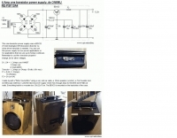
 Two types of multi-functional Home-brew 6/8Amps - 20 Ampere variable power supplies by ON6MU
 -
 Robert Norgards KL7FM's, notes on upgrading the Heathkit SB-200
 -
 SPE Makers of RF power amplifiers like Expert 1K-FA Expert 2K-FA
 -

-
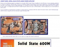 G3WZT design for a bi-polar 600W Linear Power Amplifier for the 6M band.
 -
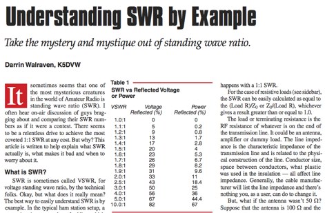 Take the mystery and mystique out of standing wave ratio. QST Article by K5DVW
 -
 WV7U's YC156 and 3CPX800 amplifier projects. Everything you wanted to know about using the YC156 or 3CPX800 in a ham radio linear amplifier. See pictures, schematics, test data, links, and more!
 -
 These instructions use simple, generally familiar examples of equipment types and are designed to help you find the adjustment that suits you best. If you are looking on how to adjust a morse key, bencher key, paddle or straight morse key, here you will find all instructions.
 -
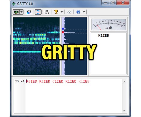 Processing a single RTTY signal from a transceiver's 3-kHz audio, GRITTY employs _Bayesian statistics_ for superior decoding accuracy compared to traditional trial-and-error methods. This approach not only decodes 5-bit Baudot codes but also calculates the probability of error for each bit, enabling features like color-highlighting unreliable characters and smart squelching based on error probability rather than signal amplitude. This allows decoding of very weak signals while suppressing strong, undecodable interference, resulting in minimal garbage text. The program intelligently analyzes decoded text, comparing similar callsigns bit by bit and merging probabilities using the Bayes formula. This often allows GRITTY to determine the correct callsign and place it on the call stack even when all received copies are corrupt. The same methodology is applied to correct errors in exchange numbers and CQ/DE keywords, and to fix incorrect shift states. GRITTY offers an open API interface, documented in its Help file, for integration with other programs, allowing them to receive decoded data and mouse click events.
 -
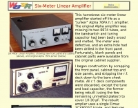 This homebrew six-meter linear amplifier started off life as a "junker" Alpha 76PA h.f. amplfier. Power output is 800W
 -
 A microphone preamplifier schematic for hand-helds by ON6MU
 -
 Information and digital audio samples of various modem modulation types
 -
 Ameritron Al-811H Tuning for Power/Dissipation/Linearity, and More Generally 811A Tube Amps in Grounded Grid
 -
 The circuit is based on two AD8307 log amplifiers, which are connected to the forward and reflected ports on a directional coupler
 -
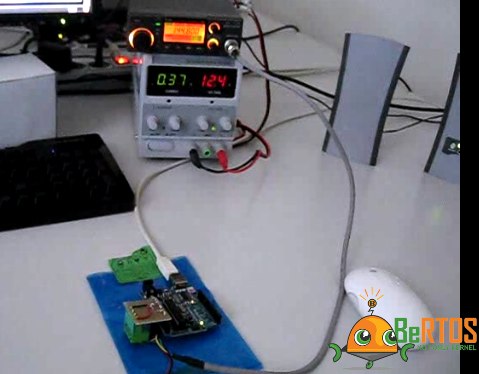 An Arduino APRS project based on the real time OS BeRTOS
 -
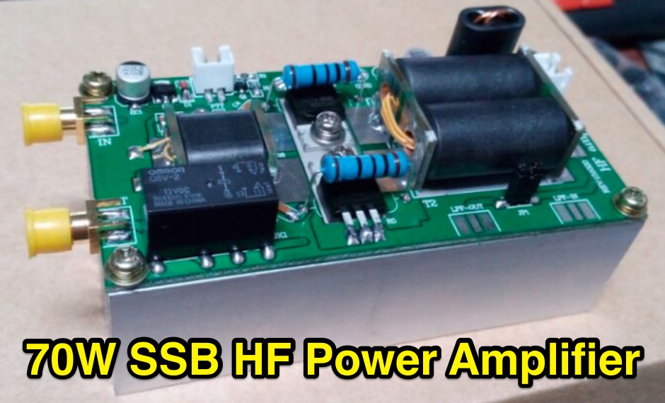 DIY kits a 70W SSB linear Power Amplifier for YAESU FT-817 KX3 running HF 80m-10m bands
 -
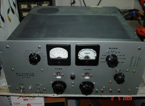
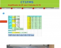 An RF power Amplifier for HF bands with 3 GI-7B tubes by CT1FMS
 -
 About different baluns types. Samples and schematics for several ratios baluns in french
 -
 This article presents a method of controlling preamps, antenna switching and polarization switching remotely without the use of control cables.
 -
 A simple RF power amplifier initially designed for 40 meter band can work on 10 15 20 40 80 meters
 -
 This article describes a project of asymmetrical hatted vertical dipole, a portable antenna that can be used for field day operations, sota, campings or even for fixed installations. This is a freestanding 20-10m antenna that is really easy to build, easy to tune and relatively easy to carry.
 -
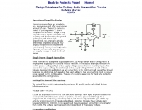 Design guidelines for Op Amp audio preamplifier circuits by Mike Martell N1HFX
 -
 A lower power desktop linear with integrated 120vac power supply. This, very compact, dual 811 version will deliver about 300 watts output. Covers all bands including WARC bands.
 -
 TX RX Systems Inc. offers a robust catalog of RF conditioning products, including **transmitter combiners**, receiver multicouplers, and various RF filters. Their extensive experience, spanning over 45 years in the RF and Land Mobile Radio (LMR) industries, underpins their specialized offerings. They provide solutions for in-building RF coverage, repeater systems, and general RF management, catering to the demanding requirements of professional radio communications. Their product line features **bidirectional amplifiers (BDAs)**, signal boosters, and cavity filters, essential components for optimizing radio system performance. The company emphasizes reliable solutions, leveraging decades of field-proven expertise in designing and manufacturing critical RF infrastructure. From duplexers to cell enhancers, TX RX Systems focuses on delivering high-quality RF components and integrated systems designed to ensure clear and consistent radio signal integrity across diverse operational environments.
 -
 This online article provides a list of individuals who hold or have held amateur radio callsigns, detailing their public recognition. The resource identifies specific callsigns such as **K1JT** (Joe Taylor, Nobel Prize in Physics), **W6OBB** (Art Bell, syndicated radio personality), and **JY1** (King Hussein of Jordan), linking them to their non-amateur achievements. It also notes operational statuses like _Silent Key_ for deceased operators and _lapsed callsign_ for inactive licenses. The article includes information on callsign changes due to vanity callsign programs and provides examples of individuals involved in specific technical areas, such as Percy L. Spencer (**W1GBE**), inventor of the microwave oven, and Jay Kolinsky (**NE2Q**), inventor of electronic sirens. It also references amateur radio involvement in _space missions_ for individuals like Owen Garriot (**W5LFL**) and Helen Sharman (**GB1MIR**). DXZone Focus: Online Article | Famous Hams | Callsign Status | Vanity Callsigns
 -
 The UK amateur radio licensing scheme features three distinct tiers: Foundation, Intermediate, and Full, each granting specific operating privileges. For instance, the **Foundation Licence** permits a maximum of 10 watts output power on most allocated bands, with restricted band access. The Intermediate Licence allows up to 50 watts, while the **Full Licence** grants access to the maximum UK legal power limits and all available amateur radio band allocations. UK call sign prefixes and formats provide insights into the licensee's class and the approximate issuance date. For example, M3, M6, and M7 prefixes with three letters denote Foundation Licences issued from 2002, 2008, and 2018 respectively. Intermediate Licences, often starting with "2E0" or "2E1" followed by three letters, were issued from 1991 onwards. Full Licences encompass a broader range of prefixes like G2, G3, G4, G0, and M0, with varying letter counts indicating different historical license classes and issuance periods, such as G3 plus three letters issued between 1946 and 1971. Special prefixes like GB are reserved for repeaters, beacons, data mailboxes, and special event stations, with specific numerical sequences (e.g., GB3 for repeaters, GB7 for data repeaters/mailboxes) indicating their function. Optional prefixes such as GC, GD, GI, GM, and GW denote specific UK countries (e.g., Wales, Isle of Man, Northern Ireland, Scotland, England) and can also signify club stations.
 -
 High Power RF Amplifiers by Delta Sigma, Inc
 -
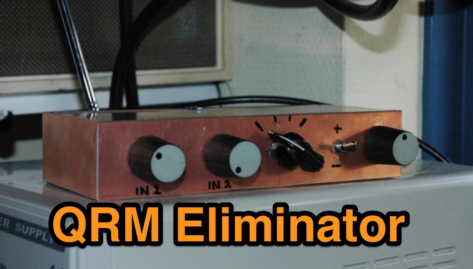 An home made QRM Eliminator project based on the WA1ION original design, used to remove QRN generated locally by an halogen lamp in Dutch
 -
 The two linear amplifiers are ment for use with QRP SSB/CW/FM/AM transmitters on the amateur bands 15 and 17 meters can be powered from a 12 volt DC supply by ON6MU
 -
 A Solid State HF Amplifier with 16 mrf150 featuring 2.4 kW 1.8 MHz - 30 MHz
 -
 HF power amplifier project powered by GU-78B by SV8JE
 -
 Manuf RF power amplifiers wideband+narrowband for Commercial, Defense, OEM and amatuer markets. Also low-noise rf amplifiers
 -
 ON6MU 4 A power supply using a BDX33
 -
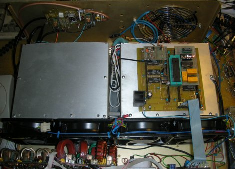
 The Collins TRC-75 autotune linear amplifier, owned by JF2SVU, is presented with a focus on its internal modifications. This QRO amplifier utilizes three 4CX250 tubes in parallel for its final stage, delivering 1 KW output power. Notably, the amplifier achieves full power with only 100 mW of RF input, a characteristic often associated with Collins designs. The original 400 Hz power supply has been converted for easier shack integration, and the entire RF and power supply sections have been rehoused into a compact, clean enclosure. The control unit, positioned above the amplifier, features three meters for individual vacuum tube IP monitoring and a multi-meter on the right. A dedicated 7 MHz receiver, recently completed, is also part of this integrated system. The autotune functionality means the main amplifier unit only requires connections for power, control, and coaxial cables, simplifying its operation. Key components like the 4CX250 tubes and NF capacitors are visible, along with the gearing mechanism for the final tank circuit. A timer and relay system manages high-voltage delay and cooling fan off-delay, although the cooling fan's airflow is noted as somewhat insufficient. A central volume control, which experienced a contact issue, is also highlighted.
 -
 Adventures in amplified GPS antenna construction; an experiment
 -
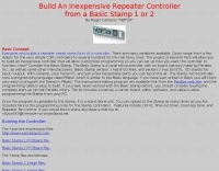 Build An Inexpensive Repeater Controller from a Basic Stamp 1 or 2 By Roger Cameron
 -
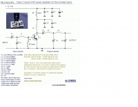 Class C tuned VHF power amplifier for the 6-meter band by ON6MU