Search results
Query: calcul
Links: 381 | Categories: 14
Categories
- Antennas > Antenna Calculators
- Technical Reference > Calculators
- Software > Antenna analysis
- Antennas > Theory > Antenna Gain
- Technical Reference > Attenuators
- Antennas > Bazooka
- Operating Aids > Distance & Bearing
- Software > EME
- Software > Grid Bearing and Maps
- Operating Aids > Grid Squares
- Antennas > HB9CV
- Software > RF Design
- Technical Reference > Components > Toroids
- Antennas > Theory > Wind Load
-
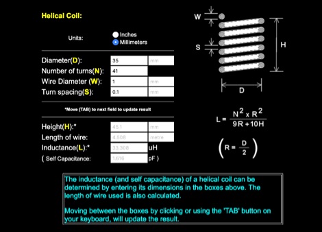 This online calculator will give as output the Inductance L of a coil, including the total lenght of the wire needed to wound the coil. As input, requires the Diameter, number of turns, wire diameter and turn spacing
 -
 This calculator ask as input diameter, lenght turn and frequencu and will return L and Q
 -
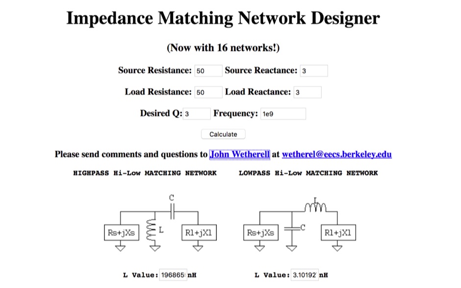 An online multiple calculator of 16 impedance matching networks
 -
 A free Labview antenna calculator program. This interesting calculator for small loop antennas can be ran on most recent Windows versions using the Labview runtime.
 -
 Constructing a basic multimeter involves integrating a 0-1mA meter movement with various shunts and multipliers, selected via a switch, to create a versatile instrument capable of measuring DC volts, current, and resistance. The design outlines two main units: a primary unit handling six DC current ranges up to 1 amp and eight DC voltage ranges up to 1000 volts, alongside an internal battery for an ohms range up to 200,000 ohms. This approach allows for a practical, hands-on understanding of meter operation. An add-on unit further extends the multimeter's capabilities, incorporating a meter rectifier and switched series resistors to provide four AC voltage ranges up to 100 volts. Additional shunt and series resistors, designated Ra and Rb, are included to expand the instrument's range to 10A and 5kV, demonstrating how modular design can enhance functionality. When this add-on is in use, the main instrument is set to measure 1mA FSD, connecting via specific lugs. Component selection emphasizes precision, with 1% tolerance high stability resistors for series elements and Eureka resistance wire for shunts. The design specifies values calculated for a meter with 60 ohms internal resistance, noting that these would require modification for different meter characteristics. Experimental adjustment of shunt values is recommended to ensure accurate readings against a calibrated reference meter, reinforcing practical calibration techniques.
 -
 Using a simple calculation, measure the distance between Earth and the Moon with the help of a local amateur radio station
 -
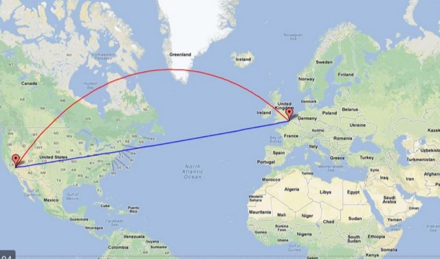
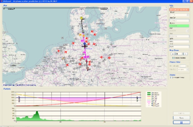 Software for Aircraft Scatter Prediction. Extend your capabilities on VHF-/UHF-SHF bands even when you live in an unprivileged location and Calculate a propagation path between two stations and follow the aircrafts in real time
 -
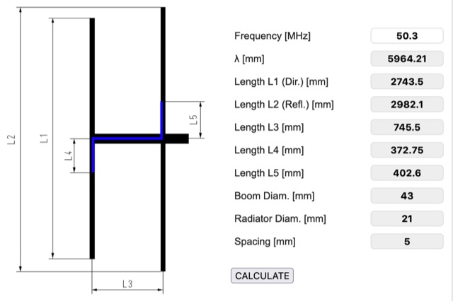 Online HB9CV antenna calculator, accept as input the desired resonating frequency and provides dimensions for spacing and length of each element, including boom and radiator diameter.
 -
 The calculator designs the Yagi-Uda antenna based on the DL6WU model with boom correction, following the G3SEK-DL6WU method. It optimizes the antenna for maximum gain and allows adjustment of passive elements without affecting SWR. DL6WU antennas are known for their high gain, minimal sensitivity to nearby objects, and stable performance in various weather conditions.
 -
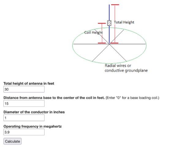 You can shorten a vertical antenna by using a loading coil. This online calculator tells you how the amout of inductance your loading coil will need to have.
 -

-
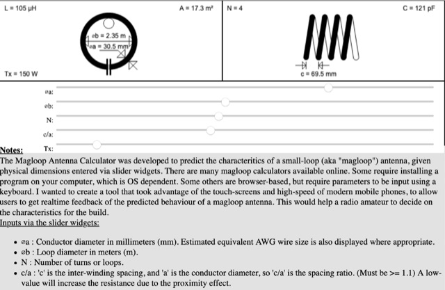 The Magloop Antenna Calculator was developed to predict the characteritics of a small-loop (aka magloop) antenna, given physical dimensions entered via slider widgets. This magnetic loop antenna calculator works also on most mobile devices, adjusting sliders and calculating dimensions in real time.
 -
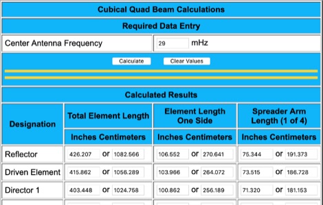 Cubical Quad Antenna On-line Calculator helps on defining the size of each element and spreader. Simply give the resonating frequency and it will calculate size of each element.
 -
 This is a standard calculation method that can help you while tuning dipole antennas, by adjusting wire lengths. This method can be used also when you need to add lenght to your wires, and can be additionally used to quarter waves vertical antennas
 -
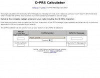 This page calculates the necessary GPS message (C1 message on most Icom radios) to use your Icom radio in GPS mode (not GPS-A mode) with D-PRS.
 -
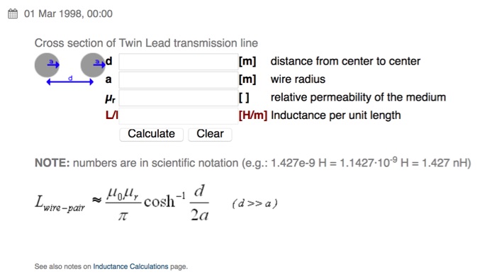 Calculate the inductance of twin lead online
 -
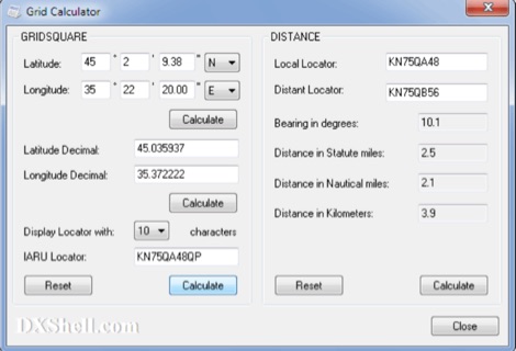 Grid Calculator allows you to calculate either a grid square locator or the latitude and longitude of a location. Grid Calculator can be used to calculate a Great Circle bearing and distance between two stations in statute miles, nautical miles, and kilometers.
 -
 A 0-30 MHz step attenuator, constructed from switchable Pi attenuation pads, provides a practical tool for evaluating receiver sensitivity and calibrating S-meters. The design utilizes readily available 5% tolerance resistors, with values derived from paralleled components to achieve specific attenuation steps. A schematic (Fig 1) illustrates the circuit, including PCB pad shielding, while a table details required and actual resistor values, along with percentage differences. Measurements of voltage input versus output at various frequencies are used to calculate dB attenuation, presented in a graph (Fig 4). The resource includes formulas for determining output voltage from a known input and a comprehensive 0-40 dB voltage multiplier table, which is crucial for precise signal level management. The project also references external attenuator calculators and equations for further study. Photos (1-3) provide visual guidance for the assembled unit, showing bottom, top, and front views. The project emphasizes the use of **Pi attenuation pads** and **receiver sensitivity** evaluation, offering a hands-on approach to RF signal management.
 -
 Free ham radio utilities written in LabVIEW includes Open Wire Calculator, Dipole Peak/Null Angle Calculator, a Coil-Shortened Antenna Calculator ad interesting Round Coil Inductance Calculator and a Skyloop Antenna Calculator
 -
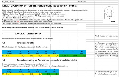 This EXCEL Program Worksheet calculates the safe operating conditons for a toroidal transformer operating between 1 and 50 MHz. Manufacturer data for complex permeability, magnetic dimensions, and saturation flux density must be available. Some core types which are commonly used in amateur transmission are included. The program produces limiting winding voltages for linear operation and temperature rise over the range of frequencies and power specified.
 -
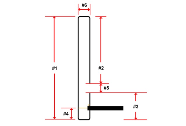 Easy to use online Slim Jim antenna calculator. Input your frequency to automatically calculate the lengths of the different antenna parts.
 -
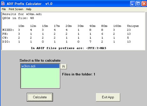 This software loads WPX type ADIF files with the <PFX:xxx> tag and calculates the different callsign prefixes. The software will load and capture the totals for big files. ADIF files must have the .adi file extension.
 -
 This resistor calculation tool shows which combinations of two resistors, series or parallel, gives a match better than the closest standard value.
 -
 Basic magnetic loop antenna examples and loop aerials theory explained. This article inclued some interesting tricks on building magnetic loop antennas and an usefull excell sheet to help compute magneti loop antennas calculating power efficiency from 10 to 40 meters band
 -
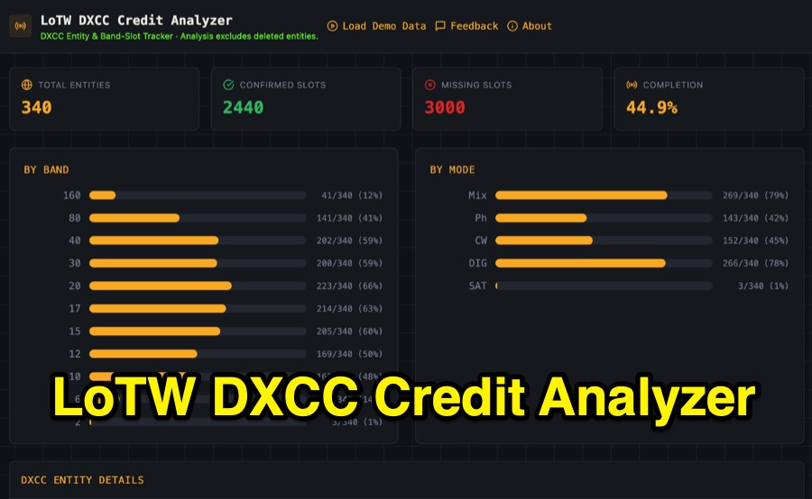 Visualizing DXCC award progress often requires manual parsing of Logbook of the World (LoTW) reports, which can be time-consuming and prone to error. This web-based utility streamlines the process by allowing hams to upload their LoTW DXCC Credit Report spreadsheet, providing an interactive dashboard for tracking confirmed entities, bands, and modes. It processes .xlsx, .xls, and .csv files, performing all calculations client-side within the browser for privacy and speed. The tool presents a comprehensive stats overview, detailing total entities, confirmed slots, and overall completion percentage. It includes progress bars for bands from _160m_ through _2m_, and modes such as CW, Phone, and DIG. A sortable DXCC Entity Details Table lists each entity, its confirmed count, and specific missing band/mode slots, with a CSV export option. Further features include a Band/Mode Matrix grid for granular confirmed status per entity, toggles for specific bands like _6m_ and _2m_, and tracking for DXCC Challenge progress across 10 eligible HF/VHF bands. It also highlights nearly complete entities and identifies most-wanted DXCC entities based on the uploaded data.
 -
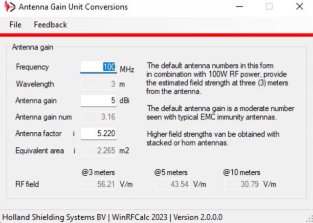 A multi tool Windows program that has been designed to offer the EMC RF and Radio Engineer a large variety of tools for Attenuation calculation, VSWR analysis, FIR Filter calculations, EMC system configuration, Radar testing , RF Filter calculation and much more without the need of a live internet connection.
 -
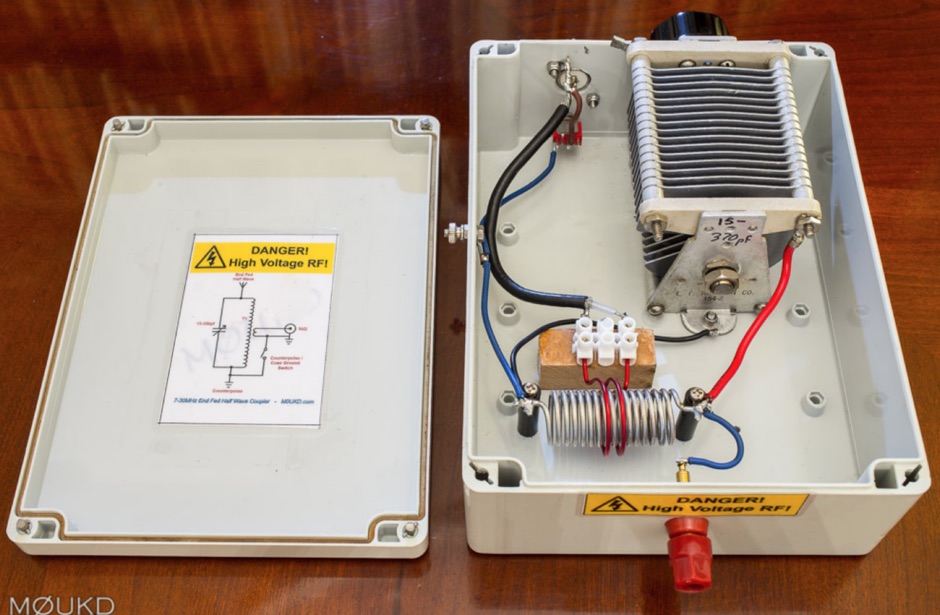 A home made end-fed half-wave antenna coupler with antenna lenght calculator and counterpoise calculator based on center frequency. Includes pictures and drawings along to antenna homebrewing instructions with a home made on air wound transformer
 -
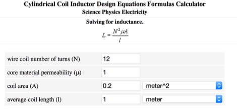 Calculate inductance online, with the cylindrical Coil Inductor Design Equations Formulas Calculator
 -
 The Tri-pole antenna, a clever modification of a standard dipole, allows for dual-band operation by integrating a third element. This design effectively shortens the overall dipole length by 10 to 20 percent, simplifying antenna rotation and offering a compact footprint. KK4OBI's article delves into the operational principles, using a 6 and 10-meter Tri-pole as a primary example, and provides comprehensive instructions for constructing any Tri-pole antenna within the 6 to 15-meter range. Key to the Tri-pole's performance is its off-center feed, necessitating a common mode choke at the feed point for optimal tuning and reduced noise. The author outlines a methodical approach to determining element dimensions, starting with a vertical element frequency calculated as 0.47 times the sum of the desired upper and lower band frequencies. This calculation, along with K-values derived from trend lines, guides the initial lengths for the horizontal arms, demonstrating how a 10m-6m Tri-pole can achieve a total horizontal length 78% shorter than a conventional 10-meter dipole. Tuning and balancing are critical, with the article detailing adjustments to arm lengths and the vertical element to achieve balanced SWR values, as validated through 4NEC2 simulations. Radiation patterns are analyzed at various elevations, showing gains around 5.7 dBi and favorable take-off angles for DX contacts. Construction details specify aluminum tubing dimensions, U-bolts, and an SO-239 connector, emphasizing the importance of a ferrite-based choke for wideband operation.
 -
 HA8TKS website dedicated to amateur radio VHF DXing include a dx-cluster map & list, HAM tools, QRB calculator and personal statistics
 -
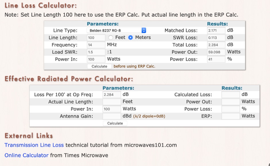 RF Feedline (Coax and Ladder-Line) Loss and ERP Calculators made with Javascript. This complex feddline loss calculator has already several line types paramenters for most common coaxial cables from Belden, Time LMR, Wireman and other common products. Result will give Matches loss, SWR loss, dB and Watts power loss.
 -
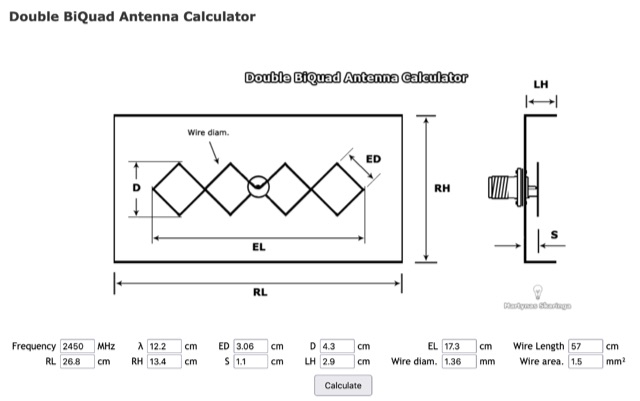 Online antenna calculator for homemade double biquad antenna for UMTS 3G 4G WiMAX WiFi frequencies. Article includes also a simple biquad antenna for 4g
 -
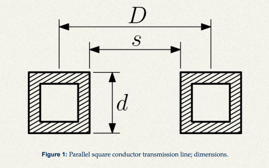 Design a parallel square stock balanced transmission line with this calculator.
 -
 A basic YAGI UDA online antenna calculator, accept as input frequency, number of elements, diameter of parasitic element and boom diameter. This online calculator will generate a basic design data including each element length and spacing.
 -
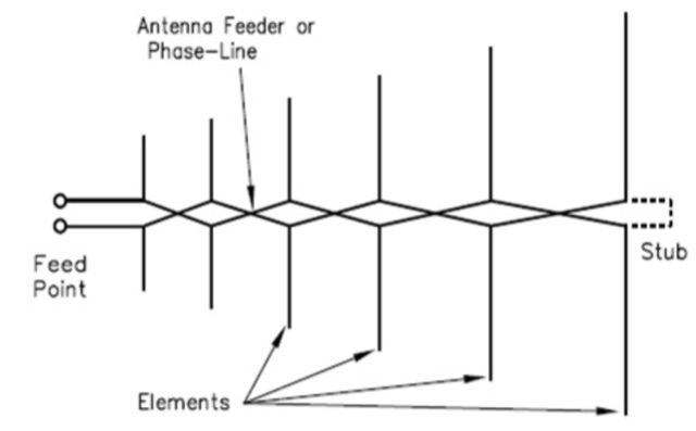 Description and online calculator for Log Periodic Dipole Arrays LPDA are directional antennas featuring a relatively constant characteristics across a wide frequency range.
 -
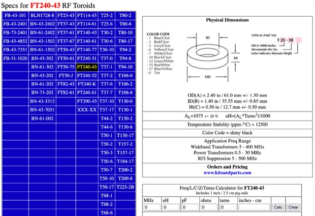 This website provide online calculator for several values about a large variety of toroids. Freq/L/C/Z/Turns Calculator, Impedance Matching Network Calculator
 -
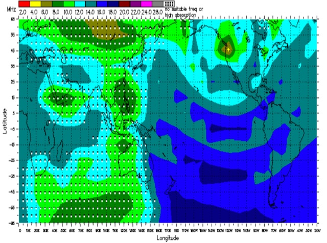 This paper presents the method of calculating the maximum usable frequency (MUF) and field strength of radio waves reflecting 2 times at the F2 ionosphere layer under inhomogeneous conditions of the ionosphere. The comparison between predicted and measured MUF has shown that the proposed method significantly increases the accuracy of calculation MUF.
 -
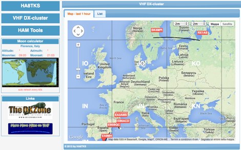 Home page with nice DX Tools, VHF DX Cluster map, QRB calculator and personal online log-book
 -
 DF0WD/DL4YHF's Longwave Overview details amateur radio operations on the 135.7 to 137.8 kHz segment in Germany. The author outlines the "inofficial" European band plan, specifying segments for QRSS, TX tests, beacons, conventional CW, and data modes. Early LF activities at DF0WD began with a 20-watt CW transmitter, later upgraded to a homemade linear transverter capable of 100 watts, driven by an Icom IC706 on 10.137 MHz. The station's antenna system includes a 200-meter wire, approximately 10 meters above ground, supported by football field light-masts. Despite its length, the antenna's efficiency is noted as very low due to the immense wavelength of about 2.2 km. The author's experience highlights the significant challenge of achieving effective radiated power (EIRP) on LF, estimating DF0WD's EIRP at around 80 milliwatts based on field strength measurements from PA0SE. DF0WD/DL4YHF has successfully worked numerous countries on 136 kHz CW, including DL, F, G, GI, GM, GU, GW, HB9, HB0, LX, OE, OH, OK, OM, ON, OZ, PA, and SM. The author also mentions ongoing efforts to log contacts with CT, EI, LA/LG, and to complete a two-way QSO with Italy, demonstrating persistent activity on this challenging band.
 -
 Blog post by Adrian M0NWK showing how to calculate the latitude and longitude at the centre of a Maidenhead locator using basic maths.
 -
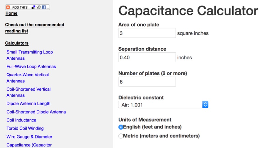 An online calculator for designing and evaluating capacitors based on the capacitor's area, separation, number, and dielectric constant
 -
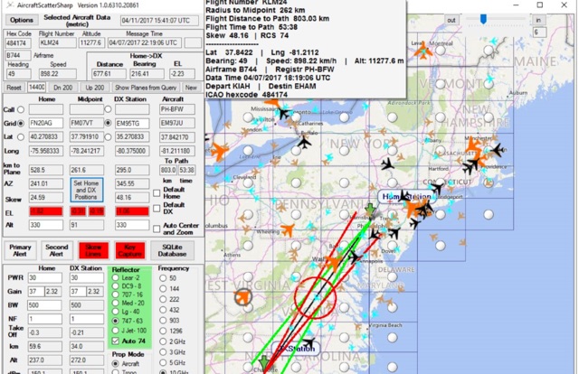 Aircraft Scatter Sharp is a windows application to calculate and assist airscatter operations. Real-time capture and display of plane position data derived from internet plane servers, highlighting of aircraft near the ideal position for scatter, Real-time estimation of Doppler shift and its rate of change.
 -
 This page delves into the Inverted V antenna, a source of myths among ham radio operators. The author explores the behavior of this antenna type with a focus on a 20m half-wave dipole positioned 10m above the ground. From Pythagoras to high school math, the article simplifies the calculation of dimensions and angles for setting up an Inverted V antenna. It includes a spreadsheet for calculating hypotenuse length and angles, crucial for antenna setup. Additionally, it provides insight into the radiation pattern of a 'flat' half-wave dipole at 10m height. Useful for hams planning to optimize their antenna setup. In Norwegian.
 -
 Calculate distance, bearing and more between Latitude/Longitude points. This page presents a variety of calculations for latiÂtude/longiÂtude points, with the formulas and code fragments for implementing them.
 -
 Determining the characteristic impedance (Z) of an unknown coaxial cable, a common challenge for many radio amateurs, can be resolved with a straightforward method. The impedance of a coaxial cable is derived from its inductance and capacitance, and importantly, these values are independent of the cable's length or the operating frequency. This means that measuring a random length of cable, such as 20 meters, provides sufficient data for calculation. The core of this technique involves an LC-meter to obtain the inductance (L) in microHenries (uH) and capacitance (C) in microFarads (uF). The impedance is then calculated using the formula Z = L/C. For instance, a measurement yielding L=1.2uH and C=450pF (0.00045 uF) results in an impedance of 51.6 Ohms, closely matching **RG-58** specifications. Similarly, a TV coaxial cable with L=1.8uH and C=320pF (0.00032 uF) calculates to 75 Ohms. While the accuracy of this method, depending on the LC-meter's tolerance, is approximately 10%, it proves sufficiently precise for practical determination of unknown coaxial cable impedance, as noted by Makis, SV1BSX, who credits Cliff, K7RR, for the formula's dissemination.
 -
 Enables Android users to operate various _miniVNA_ antenna analyzers via Bluetooth, USB, or Wi-Fi, providing a portable solution for RF measurements. The application supports full control over data acquisition, offering features like custom frequency range selection from 1 KHz to the VNA's full range, and automatic screen adaptation for diverse Android device resolutions. It facilitates intuitive, wizard-based calibration for both reflection and transmission modes, saving calibration data for different VNA types (Standard, Pro, Pro with Extender) to avoid repeated procedures. The software displays critical parameters such as SWR, |Z|, Return Loss, Phase, Rs, and |Xs| on 2-axis graphs or Smith charts, with multi-touch gestures for zoom and frequency shift. It includes a frequency generator mode with independent channels and attenuator control for the miniVNA Pro, along with a sweeper function. The cable data mode automatically calculates phase and loss, measures cable length from less than 1 meter to hundreds of meters, and includes a table of common coax cable velocity factors. An experimental X-tal mode measures resonance frequency, Rs, and Q. Data export options include CSV, ZPLOT, and S1P formats, with CSV import capability. The application also features an SM6ENG Audio mode for SWR tuning without visual reference and provides a miniVNA battery voltage indicator. It supports a wide frequency range, with the miniVNA Extender extending coverage up to **1500 MHz**. The application is compatible with Android version 2.2 and later, tested on devices like the _Galaxy TAB 7.7 P6800_.
 -
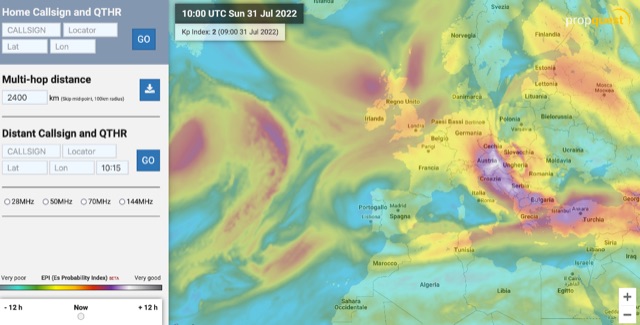 The map display allows you to select by locator, or clicking on the map, where you want to calculate the probability of Sporadic-E by building a combination EPI, Es Probability Index, based on factors using many of the known parameters which can effect Es. T
 -
 A 60-foot available space, for example, might necessitate a shortened multiband dipole array to cover 80, 40, and 15 meters effectively. This resource details the construction of such an antenna, combining full-size and coil-loaded dipoles on a single feedline. It addresses the common challenge of fitting multiple HF bands into restricted physical footprints, providing practical guidance for hams with smaller backyards or portable operations. The core of the offering is an interactive calculator that determines required loading coil inductance and dipole lengths for various amateur bands from 160m to 10m. Users input their available space, and the tool provides dimensions, coil turns, and an efficiency rating (Good or Fair) based on the antenna's electrical length relative to a quarter-wavelength. It also suggests suitable _PVC_ pipe diameters for coil forms. The article further illustrates a center feed-point assembly using an 18-inch section of 2-inch _PVC_ pipe, detailing eye-bolt spacing and coaxial connector installation. It emphasizes the importance of adequate spacing between parallel dipoles and offers customization options for the feed-point, including the addition of a _Balun_ for improved feedline isolation.
 -
 Microwaves101 provides an extensive repository of information covering fundamental principles of microwave design, targeting engineers and radio amateurs interested in the higher frequency spectrum. The site features a detailed _encyclopedia_ of microwave terms and concepts, alongside practical design considerations for various components and systems. It serves as a foundational reference for understanding RF propagation, transmission lines, and active/passive microwave circuits. The resource includes numerous calculators for impedance matching, filter design, and other critical RF parameters, facilitating hands-on project development. Discussions on **10 GHz** equipment and **24 GHz** projects highlight practical amateur radio applications, extending to operations up to 134 GHz. Content spans from basic theory to advanced topics like MMIC design and antenna characteristics, supporting both educational and practical endeavors in microwave technology.
 -
 10 Elements Cross-Yagi Antenna for 433 MHz. The base of the 10el antenna is the recalculated RA6FOO antenna.Circular polarization is realized - by a phasing quarter-wave line, matching of horizontal and vertical polarization antennas