Search results
Query: meter band
Links: 907 | Categories: 22
Categories
- DX Resources > Beacons > 10 meter beacons
- Antennas > 20M > 20 meter Dipole Antennas
- Antennas > 20M > 20 meter Vertical Antennas
- Antennas > 20M > 20 meter Yagi antennas
- Antennas > 40M > 40 meter Dipole Antennas
- Antennas > 40M > 40 meter Loop Antennas
- Antennas > 6M > 6 meter J-Pole Antenna
- Operating Modes > Top Band
- Antennas > 40M > 40 meter Yagi Antennas
- Antennas > 6M > 6 meter Moxon Antennas
- Antennas > 10M
- Antennas > 17M
- Antennas > 20M
- Antennas > 2M
- Antennas > 30M
- Antennas > 60M
- Operating Modes > 70 MHz
- Antennas > 80M
- Radio Equipment > HF Vertical Antenna > Cushcraft R8
- Antennas > Halo
- Radio Equipment > HF YAGI Antennas > Hy-Gain TH3JR
- Antennas > Morgain
-
 An experimental antenna similar to the TAK spiral antenna was evaluated for SWR response over the frequency range of 7.0 to 7.3 MHz, or the 40-meter band.
 -
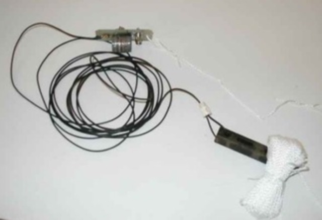
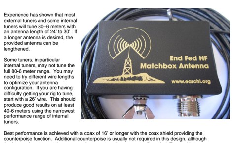 6m to 40m EndFed Half Wave Antenna project produces an inexpensive, multiband, end fed HF antenna matchbox that is quick and easy to setup and use.
 -
-
 The document details the optimization and construction of the _Maria Maluca_ antenna, a compact 6-band (20m-6m) directional beam. It presents a comparative analysis of shortwave antenna principles, highlighting the efficiency gains achieved by using an open feeder line and tuner as a resonant unit, contrasting this with the losses associated with traps or capacitive loads in multiband antennas. The resource specifically revisits an older South American 2-element design for 10, 15, and 20 meters, applying modern NEC-based software to develop a six-band version. Performance data is meticulously tabulated, showing impedance, free space gain, gain at 12m height, elevation angle, and front-to-back (F/B) ratio for each band from 20m through 6m. For instance, on 15m, the antenna achieves 5.1 dBd free space gain and 13.72 dB F/B ratio. The construction section provides practical guidance on element assembly using aluminum pipes and hose clamps, detailing the use of a heavy-duty glass fiber reinforced polyamide rod for electrical separation and bending strength. It also specifies the use of 450-ohm _Wireman_ line CQ 552 for the transmission line. The document includes diagrams for rod fixing, an air-wound balun, and a vertical elevation diagram for the 15m band, illustrating its DX qualification. It also discusses the antenna's suitability for portable and expedition operations, noting its compact transport dimensions (max 1.50m length, 12 lb weight) and quick assembly time (under 15 minutes). The author, Dipl.Ing. Helmut Oeller, DC6NY, is identified as a source for material kits.
 -
-
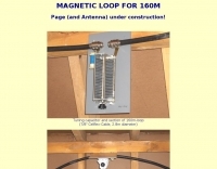 Pictures and calculated values for this home made magnetic loop antenna for the 160 meters band by HB9MTN
 -

-
 The article "Exploring the World of 10 Meter Beacons" by Ken Reitz, KS4ZR, provides an in-depth look at 10-meter beacon operations, focusing on their utility for propagation analysis. It details FCC Rules part 97.203 governing beacon stations, including license requirements, power limits (under 100 watts), and the specified band segment of 28.200-28.300 MHz for U.S. operations. The content highlights the diversity in beacon construction, from converted CB radios to home-brew QRP transmitters, and discusses the robust operating conditions these 24/7 stations endure. The resource presents several case studies of active 10-meter beacon operators like Ron Anderson KA0PSE/B, Domenic Bianco KC9GNK/B, and Bill Hays WJ5O/B, detailing their equipment, antenna setups, and typical signal report volumes. It also introduces the NCDXF/IARU International Beacon Project, which features 18 synchronized beacons worldwide transmitting on 28.200 MHz at varying power levels (100W, 10W, 1W, 100mW) to facilitate propagation testing. The article also covers the PropNet Project utilizing PSK31 on 28.131 MHz and the 250 Synchronized Propagation Beacon Project on 28.250 MHz. Practical advice for monitoring includes using the RST reporting method, understanding the impact of the solar cycle on 10-meter propagation, and tips for setting up a personal beacon, such as frequency selection and power output considerations. The IY4M Guglielmo Marconi Memorial Beacon Robot on 28.195 MHz is also mentioned for its automatic QSO mode. The article concludes with a list of other resources for 10-meter beacon information.
 -
-
 The G5RV antenna, a popular multi-band wire antenna, typically employs a center-fed design with a specific length of 300-ohm or 450-ohm open-wire line acting as an impedance transformer, feeding a coaxial cable run to the shack. Its overall length for 80-10 meters is approximately 102 feet (31 meters) for the flat-top section, with a 34-foot (10.36 meter) matching section. The original design by Louis Varney, G5RV, aimed for efficient operation on 14 MHz (20 meters) as a 3-half-wave antenna, with the matching section providing a good match to 50-ohm coax on that band. While the G5RV offers multi-band capability, its performance varies across bands, often requiring an antenna tuner for optimal SWR on bands other than 20 meters. The matching section's length is critical for its impedance transformation properties, influencing the feedpoint impedance presented to the coaxial cable. Variations like the G5RV Junior and ZS6BKW utilize different flat-top and matching section lengths to optimize performance for specific band sets or to achieve a lower SWR without a tuner on certain bands, demonstrating the adaptability of the basic G5RV concept.
 -

-
 An experimental fractal Quad antenna for 10 meter band project by AG1LE
 -
 A 7 elements yagi beam monoband antenna for 14 Mhz by VE3GK
 -
-
 Article on the HF dual band antenna with construction details and how to add 160 meters to the HF2V
 -
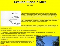 How to build a ground plane antenna for the 40 meters band in french
 -
 An easy to build single wire antenna for 160 and 80 meters with a better than 2 to 1 swr across the 80 meter band by K5GP
 -
 A 40 ft vertical dipole antenna that can cover HF Bands from 80 to 10 meters winding a dipole in a 12m HD telescoping fiberglass pole
 -
 Homebrew a vertical antenna for 40 and 80 meters band based on popular HF2V model by DL7JV
 -
 1/2wave vertical antenna for the 6-meterband and a 5/8 ground plane antenna for 50 Mhz
 -
 How to homebrew an hex beam antenna for 20 17 15 12 10 meters band by VA7ST
 -
 VE7CA experiments on 160 meters band antennas, looking for better performances on reception.
 -
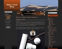 Homebrew a 2 meter 1/4 wave vertical antenna for the 146 mHz ham radio band
 -
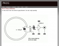
 Constructing a compact, two-band magnetic loop antenna for HF operation, especially from constrained locations like a balcony, presents unique challenges. OK1FOU's design, inspired by DJ3RW's 50 MHz loop, addresses these by employing an unusual side-fed configuration and placing the symmetric, two-section variable tuning capacitor at the bottom of the loop, directly connected to the coax shield. The article provides specific material recommendations, including two 1-meter wooden pales and about 3 meters of thick loudspeaker cable, noting the high current (60A at 100W) in the loop. Construction steps detail forming two turns with a 5 cm gap, using a GDO to pre-tune the open loop to a frequency slightly above the desired highest band, and then integrating the tuning and coupling capacitors. For 10/14 MHz, an open loop resonance of 16-17 MHz is suggested. Practical experience with the 10 MHz band from a third-floor balcony in Prague (JO70GC) shows a 1:1 SWR across most of the band without an external ATU. While DX traffic was modest due to the urban environment, QSO examples with RA6WF, LA6GIA, G0NXA, and LZ1QK on 10 MHz are provided, demonstrating its operational capability.
 -
 A project for a portable antenna for amateur radio satellite reception, for 2 meters and 70 centimeters bands
 -
 The RigPix database entry provides a comprehensive technical overview of the Icom IC-746 amateur HF/VHF transceiver, detailing its operational parameters and physical characteristics. It specifies the transmit frequency ranges across 10-160 meters plus WARC bands, 50-54 MHz, and 144-146/148 MHz, alongside receive coverage from 0.03-60 MHz and 108-174 MHz. The resource outlines supported modes including AM, FM, SSB, CW, and RTTY, noting a tuning step resolution down to 1 Hz and a frequency stability of ±5 ppm. Key electrical specifications are presented, such as a 13.8 VDC power supply requirement, current drain figures for RX (1.8-2 A) and TX (Max 20 A), and RF output power ranging from 5-40 W for AM and 5-100 W for FM, SSB (PEP), and CW. The entry details the triple conversion superheterodyne receiver system, listing IF frequencies at 69.01 MHz, 9.01 MHz, and 455 KHz, along with sensitivity ratings for various modes and bands. Transmitter section specifics include modulation systems and spurious emission levels. Additional features like a built-in auto ATU, electronic keyer, simple spectrum scope, DSP, and CI-V computer control are noted. The page also lists related documents, modifications, and an extensive array of optional accessories, including various filters, microphones, and external tuners, providing a complete profile of the IC-746.
 -
 A delta loop antenna for 17 meters band include eznec antenna model file
 -
 A vertical antenna for 40 and 80 meters band with no need of antenna tuner, based on a telescopic fiberglass mast of 48 feet by N8NSN
 -
 Presents the design and construction of the OK2FJ Bigatas, a portable, automatically tuned vertical antenna covering 80 through 10 meters. It details two distinct control systems: one utilizing BCD band data from Yaesu FT-857/897 transceivers, and another employing voltage level sensing for the Yaesu FT-817. The resource provides specific instructions for building the antenna's radiating element, loading coil with switchable taps, and the control circuitry, emphasizing the use of readily available components. The article outlines the physical construction of the antenna, including the use of duralumin tubes for the radiator and a PVC tube for the coil form. It specifies coil winding details, tap points, and the integration of radial wires for ground plane operation. The control electronics section provides schematics and component lists for both the BCD decoder (using a 74LS42 IC) and the voltage comparator (using an _LM3914_ bargraph driver), enabling rapid, automatic band switching without the minute-long tuning delays common in other systems. Crucially, the antenna achieves rapid band changes, with typical SWR values centered on common operating segments, such as **3.7 MHz** for 80m SSB. It also discusses modifications for CW operation on 80m and the trade-offs between antenna efficiency and full-range automatic tuning on higher HF bands, where manual adjustment of radiator length is suggested for optimal performance on 15m, 12m, and 10m. The resource includes construction photos and a discussion of cable requirements for reliable operation.
 -
 This resource details the computer-optimized design of the _ZS6BKW_ multiband dipole, an evolution of the classic _G5RV_ antenna. It begins by referencing the original 1958 RSGB Bulletin article by Louis Varney G5RV, explaining the operational principles of the G5RV's flat-top and open-wire feedline on 20m and 40m, noting its impedance transformation characteristics for valve amplifiers of that era. The article then transitions to the rationale for optimizing the design for contemporary solid-state transceivers requiring a 50 Ohm match. The core of the project involves using computer modeling to determine optimal lengths for the flat-top and matching section, aiming for a VSWR of less than 2:1 on multiple HF bands. It discusses the process of calculating feedpoint impedance based on antenna length and frequency, referencing professional literature from Professor R.W.P. King at Harvard University. The analysis also considers the characteristic impedance (Z(O)) of the open-wire line, identifying a broad peak of adequate values between 275 and 400 Ohms. Specific design parameters for the improved ZS6BKW are presented, including a shorter flat-top and a longer matching section compared to the original G5RV, with a velocity factor of 0.85 for the 300 Ohm tape. The article confirms acceptable matches on 7, 14, 18, 24, and 28 MHz bands when erected horizontally at 13m, and also discusses performance in an inverted-V configuration, noting frequency shifts. The author, Brian Austin ZS6BKW, emphasizes the antenna's suitability for modern 50 Ohm coaxial cable without a balun.
 -
 JJ0DRC's HF multi-band delta loop antenna project, initially conceived during the waning peak of Cycle 23, addresses the common challenge of achieving effective DX operation from a small residential lot in Japan. Dissatisfied with a ground plane antenna's performance in SSB pile-ups, the author sought a beam-like solution without a tower, drawing inspiration from a JJ1VKL article in CQ Ham Radio Sep. 2000. The antenna, constructed in October 2000, employs two 7.2-meter fishing rods (37% carbon fiber, reinforced with cyano-acrylate glue and aluminum tape) and 1mm enameled wire, fed by an Icom AH-4 external antenna tuner. While the exact beam pattern remains unmeasured, JJ0DRC observed a significantly higher callback rate compared to dipole antennas, particularly on higher bands. The system's circumference length of 15-20m is crucial for maintaining a good beam pattern across HF bands, though performance on lower bands like 80m, 40m, and 30m becomes less directional as the length deviates from a full wavelength. Ongoing maintenance addressed degradation issues, including aluminum tape cracking and wire breakage at connection points due to strong winds (often exceeding 10-15m/s in winter). The author reinforced rod connections with IRECTOR PIPE SYSTEM components and INSU-ROCK ties, and improved wire attachment methods using Cremona rope and epoxy bond to enhance durability.
 -
 F6CHT plan for a multiband yagi antenna that covers 6 to 30 meters band in french
 -
-
 A ranking of receiving antennas based on noise being evenly distributed in all directions. These rankings are most accurate in the frequency range of AM broadcast, 160 or 80 meter bands
 -
 For radio amateurs engaged in propagation studies and DXing on the 6-meter band, understanding the distribution of active beacons is crucial for assessing band openings and signal paths. This resource presents a static map compiled by _Carl-Axel Lindberg, SM6NZV_, illustrating the geographical placement of European beacons operating on the 50 MHz band, which is vital for monitoring sporadic-E, F2-layer, and other propagation modes. The map, last updated in April 2002, serves as a historical reference for beacon locations, allowing operators to correlate observed signal reports with known beacon positions. While not real-time, it provides foundational data for analyzing past propagation events and understanding typical beacon coverage areas across the European continent. Operators can use this information to identify potential receive stations or transmit points for future _DX contacts_ on the _Magic Band_.
 -
 VHF Optimized Yagi Antenna for the 6-meter band (50 Mhz) by ON6MU
 -
 A vertical half-moxon for the 7 Mhz by F6IRF
 -
 A quarter wave vertical end-fed antenna for the 40 meters band. As all vertical antennas, also this aerial requires a good earthing system. In this project the ground is composed by twelve 4, wires buried in the lawn by using a spade to create a slit to drop the wire into.
 -
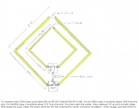
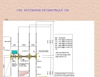
 A multiband antenna that can work from 80 to 10 meters in this illustrated docuemnt by G8ODE
 -
 A simple antenna that can be erected very fast, only need one center support, and do not take up much storage room. Works from 40 to 10 meters band
 -
 Presents a comprehensive guide for constructing a broadband Hex Beam antenna, a popular directional array for HF operation. This design offers a compact footprint and excellent gain characteristics, making it suitable for limited space installations while providing significant performance advantages over omnidirectional antennas. The resource details the specific dimensions for a five-band Hex Beam covering 20, 17, 15, 12, 10, and 6 meters, emphasizing the critical element spacing and wire lengths required for proper resonance and pattern. It outlines the construction of the center post, spreaders, and wire elements, along with the feed point assembly, ensuring proper impedance matching. The project aims for a forward gain of approximately **5.5 dBi** on most bands, with a front-to-back ratio often exceeding _20 dB_. Building this antenna requires careful measurement and assembly, but the resulting performance provides a substantial upgrade for DXing and contesting.
 -
 3 Band vertical Marconi-antenna for the bands 40, 80, 160 meters with a ground net of wires as radials.
 -
 By ON4CFC Pascal, describe how to build a Sperrtopf or Sleeve antenna for the 144 Mhz, PDF File by antennex
 -
 A shortened dipole for 40 meters band by Martin E. Meserve
 -
 30/17/12 and 20/15/10-Meter Tribanders and a 40 meters inverted V wire yagi antenna
 -
 Pictures of a 2 meter, 220, 440 copper J-Pole antennas
 -
 This project outlines the construction of a 3-element reversible quad antenna specifically designed for the 40-meter band. The materials required include pushup towers, pressure-treated posts, insulated wire, and various electrical components such as relays and a balun. The construction process is straightforward, beginning with the installation of the posts in a straight line, followed by the assembly of the antenna elements and their elevation to the desired height. The antenna's design allows for directional signal reception, making it ideal for operators looking to enhance their communication capabilities on the 40-meter band. The project includes detailed instructions on tuning the antenna for optimal performance, ensuring that operators can achieve the lowest SWR possible. Additionally, the design can be adapted for other bands by extrapolating dimensions, providing versatility for amateur radio enthusiasts. Overall, this reversible quad antenna project is suitable for both beginners and experienced operators, offering a practical solution for improving signal strength and directionality in 40-meter communications.
 -
 A Mini Moxon antenna for 40 meters band project in a well done PDF document
 -
 A monoband yagi for 14 MHz a PDF article from 73 amateur radio magazine by AB4GX
 -