Search results
Query: ring antenna
Links: 698 | Categories: 28
Categories
- Antennas > Antenna Books
- Manufacturers > Antenna Launcher
- Manufacturers > Antenna Masts and Mounts
- Manufacturers > Antenna Parts
- Shopping and Services > Antenna Parts
- Manufacturers > Antenna Rotators
- Manufacturers > Antenna Switches
- Manufacturers > Antennas > VHF UHF Microwave > Microwave antennas
- Manufacturers > Accessories
- Manufacturers > Antenna Parts > Aluminium Tubing
- Shopping and Services > Amateur Television
- Shopping and Services > Regional > Australia
- Shortwave Radio > Beginner's guides
- Radio Equipment > HF Vertical Antenna > Butternut HF2V
- Manufacturers > Antennas > CB
- Shopping and Services > CB Radio Stores
- Radio Equipment > HF Vertical Antenna > Cushcraft R8
- Shopping and Services > Ham Radio Insurance
- Shopping and Services > Ham Radio Stores
- Antennas > Longwave
- Radio Equipment > HF Vertical Antenna > Maldol MFB-300
- Manufacturers
- Shopping and Services > Marine Radio
- Manufacturers > Microwave
- Antennas > Repair and Maintenance
- Software > Satellite tracking
- Manufacturers > Shipping Cases
- Internet and Radio > Video
-
 A Loop Fed Array Yagi antenna for 50 MHz featuring 11 dBi gain and 23 f/b ratio. In this excellent page the author even includes a detailed drawing in DWG format, with element lenght and spacing measures, in a separa file a full list of material list needed to build this yagi antenna including source and price, the EZnec file for this antenna plan, and a lot of pictures of this LFA Yagi for 50 Mhz. A ten page PDF file containing all infos, is also available to download.
 -
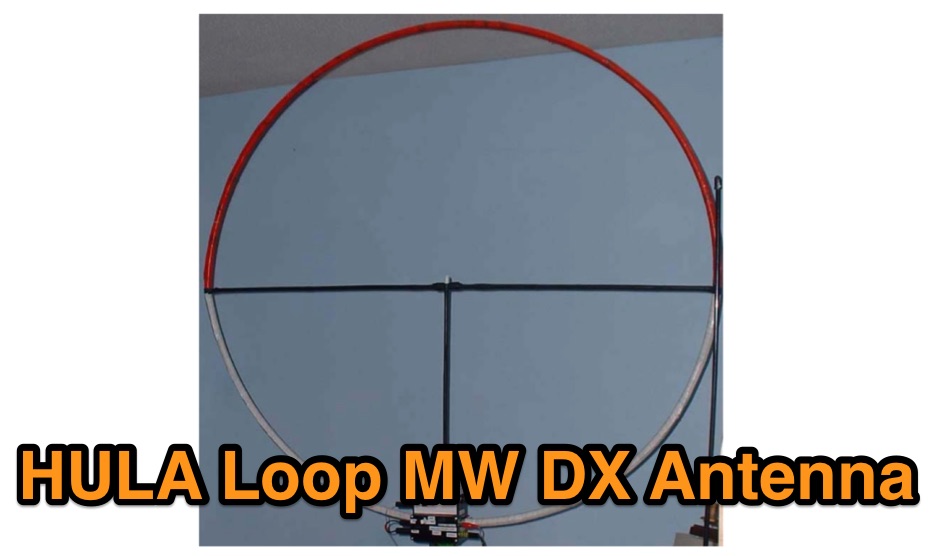 An excellently presented article on the design and construction of a medium wave DX Antenna
 -
 Deploying robust antenna infrastructure for both fixed and portable operations often requires specialized support structures capable of withstanding environmental stresses while providing optimal radiating element placement. SMC offers a range of solutions, including pneumatic masts and push-up masts, designed to facilitate rapid deployment and reliable long-term support for various antenna types. Their product line encompasses antenna mounts, poles, and complete antenna systems, addressing the critical need for stable and efficient RF communication. The company's offerings extend to HF antennas, including dipoles and _NVIS_ (Near Vertical Incidence Skywave) antennas, which are crucial for short-range regional communications on bands like 80m and 40m. These systems are engineered for durability and performance, ensuring signal integrity across diverse operating conditions. With over **65 years** of experience, SMC has established itself as a global manufacturer in this niche. Their product portfolio also includes antenna support towers, catering to more permanent installations requiring significant height and load capacity for multiple arrays.
 -
 One point eight MHz to 30 MHz is the operational bandwidth for this 4:1 Ruthroff voltage balun, designed to interface an unbalanced T-Match network with a balanced antenna system. The project details the construction using a _T200-2_ powdered iron toroid core, tightly wrapped in PVC electrical tape for insulation, and wound with 17 double bifilar turns of 1.25mm enamelled copper wire. This outboard balun offers flexibility, allowing hams to trial various baluns based on antenna system and impedance characteristics, rather than integrating it directly into the tuner. The resource includes a schematic of the balun, a wiring diagram showing winding connections, and a table suggesting alternative toroid cores like the T80-2 or T400-2 with corresponding winding counts. Component sourcing is straightforward, listing items such as the _Amidon_ T-200-2 core, SO-239 connector, and a sealed polycarbonate enclosure from Jaycar. Performance evaluation was conducted using an _AIM 4170C_ antenna analyser, demonstrating efficient 1:4 voltage transformation across the specified HF spectrum. Further efficiency tests involved measuring RF power loss at various frequencies, revealing minimal loss—less than 0.7 dB from 3.6 MHz to 30 MHz, and only 2.0 dB at 1.8 MHz. These measurements, performed under ideal 50-ohm conditions, confirm the balun's effectiveness as a low-loss interface for multi-band antenna systems. The page also links to several other balun and unun projects, including 1:1 current and voltage baluns, and 9:1 voltage ununs, providing a broader context for impedance matching solutions.
 -
 US Antenna manufacturer offering base and mobile antennas for 2 meter, 1.25 meter and 70 cm Amateur Radio GMRS and MURS Citizens Band Radio VHF and UHF Business Band Radio HF, VHF and UHF Scanning
 -
 The resource presents a detailed schematic for constructing a dual-band vertical antenna, specifically designed for operation on the 2-meter and 70-centimeter amateur radio bands. It illustrates the physical layout, critical dimensions, and component placement necessary for successful replication. Key elements such as the radiating elements, phasing sections, and feed point are clearly depicted, providing a visual guide for radio amateurs undertaking a homebrew antenna project. The diagram specifies the lengths for the VHF and UHF sections, indicating how these elements are integrated to achieve dual-band functionality from a single coaxial feedline. It also implies the use of common materials readily available to most experimenters, focusing on simplicity and effectiveness in its design. The visual format of a GIF image ensures direct access to the construction details without requiring extensive textual interpretation. This schematic serves as a practical reference for hams interested in building a compact, efficient vertical antenna for local and regional FM communications, offering a proven design for immediate implementation.
 -
 Presents a curated collection of newsletters dedicated to _Earth-Moon-Earth_ (EME) communications, primarily focusing on the 432 MHz band and higher microwave frequencies. The resource details various EME DX experiences and news contributions from operators like K2UYH (W6/PA0ZN), offering insights into successful moonbounce contacts and operational strategies. It serves as an archive of specialized content for those engaged in or interested in extreme weak-signal propagation via the moon. The newsletters provide practical information on achieving EME contacts, often including details on station setups, antenna arrays, and signal reports from challenging DX. For instance, operators might report achieving contacts over **750,000 km** round trip, demonstrating the feasibility of long-distance communication on UHF and microwave bands. The content differentiates itself by concentrating on the unique technical and operational aspects of EME, which contrasts significantly with terrestrial DXing, providing a specialized knowledge base for advanced amateur radio operators.
 -
 Optimizing the ZS6BKW antenna for full HF band coverage often requires specific modifications beyond its standard configuration. This resource details several enhancements, beginning with a simple series capacitor to improve 80m SWR, a technique W5DXP found effective for permanent installation due to its minimal impact on higher bands. Further improvements include a 10-inch parallel open stub for 10m resonance, shifting the frequency to 28.4 MHz with an SWR of approximately 1.8:1, a practical solution for Technician class operators. The document then explores a switchable matching section, adding or subtracting one foot of ladder line at the 1:1 choke-balun, which significantly impacts higher frequency bands and eliminates the need for a tuner on 17m. W5DXP's _AIM-4170D_ antenna analyzer measurements confirm these effects. More advanced modifications involve a parallel capacitor for further 80m SWR reduction, requiring remote switching for multi-band operation, and relay-switched parallel capacitors at specific points on the 450-ohm matching section to achieve low SWR on 60m, 30m, and 15m. These detailed steps, including _Smith chart_ analyses for the challenging bands, aim to transform the ZS6BKW into a truly all-HF-band antenna, reflecting W5DXP's practical experience in antenna tuning.
 -
 Prince Edward Island. The PEI DX Lodge offers a turnkey operation from a custom designed shack featuring state of the art transceivers/amplifiers, etc. and the ultimate in antennas on every band.
 -
 A complete guide to magnetic loop antenna construction, with analysis of multi-turn and single-turn magneti loops, and and insight on choosing the optimal capacitor, or homebrewing your own butterfly capacitor
 -
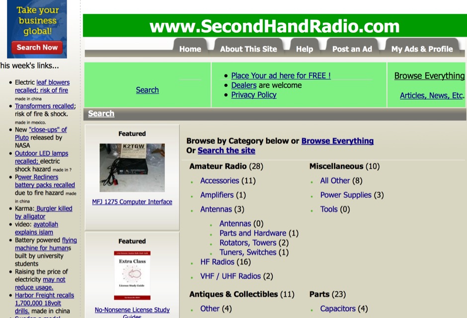 SecondHandRadio.com provides a platform for the amateur radio community to buy, sell, and swap used, surplus, and obsolete electronics and electrical equipment. The site facilitates transactions for a wide range of items, including ham radio transceivers, test equipment, shortwave receivers, antennas, and vintage radio components like tubes. Users can place classified advertisements with photos at no cost, catering to individuals, radio clubs, and commercial dealers seeking to liquidate or acquire gear. The platform emphasizes ease of use with a straightforward sign-up process and no associated fees or commissions for listing or selling items. It positions itself as a primary resource for used electronics within the USA, fostering a direct connection between sellers and buyers without intermediary charges. The service supports various categories beyond amateur radio, extending to military radios and antique equipment, thus serving a broad spectrum of radio enthusiasts and collectors.
 -
 The ZS6BKW multiband antenna, an optimized variant of the classic G5RV, features a 102-foot (31.1 m) horizontal span and a 39.1-foot ladder line matching section. This design, derived by G0GSF (formerly ZS6BKW) in the early 1980s using computer programs and _Smith charts_, aims for improved SWR across multiple HF bands compared to its predecessor. Construction details specify Wireman 554 ladder line and #14 AWG THHN copper wire for the radiators, with precise instructions for determining the velocity factor (VF) of the ladder line using an antenna analyzer or dip meter, ensuring accurate physical length for the matching section. The radiator length is electrically 1.35 wavelengths for the 20-meter band, requiring careful trimming during tuning. Field measurements with an _AIM-4170C_ analyzer by KI4PMI and NC4FB demonstrated good SWR curves and bandwidth on 6, 10, 12, 17, 20, and 40 meters. The antenna was deemed unusable on 15 and 30 meters due to very high SWR, but an LDG AT-100PRO autotuner successfully brought 6 and 80 meters into tune. Contacts were made on 80, 40, 20, and 17 meters, including a **17-meter** contact to Spain. EZNEC models for 80-6 meters are provided, along with an AutoEZ model by AC6LA, which predicted good SWR for 80-10 meters. W5DXP's modifications for an all-band HF ZS6BKW are also referenced.
 -
 The _Italian VHF Beacons_ resource provides a detailed listing of active and QRT amateur radio beacons operating across VHF, UHF, and SHF bands within Italy. Each entry specifies the beacon's callsign (e.g., IQ1SP/B), operating frequency (e.g., 144.411 MHz), QTH locator (e.g., JN44VC), effective radiated power (ERP) in watts, and antenna configuration (e.g., Big Wheel, 4x Dipole, Yagi). This data is crucial for radio amateurs involved in propagation studies, equipment testing, and long-distance (DX) communication on these higher frequency bands, offering fixed signal sources for monitoring. This compilation, last updated in October 2005, serves as a historical snapshot of Italian beacon activity. For instance, it lists several 144 MHz beacons with ERPs ranging from **0.1W** to **10W**, and higher frequency beacons such as I8EMG/B on 1296.880 MHz and I3EME/B on 24192.132 MHz. The inclusion of QRT (Quiet Radio Teletype) status for many entries indicates the dynamic nature of beacon operations over time. Users can utilize this information to identify potential signal sources for band openings or to calibrate their receiving equipment against known transmissions.
 -
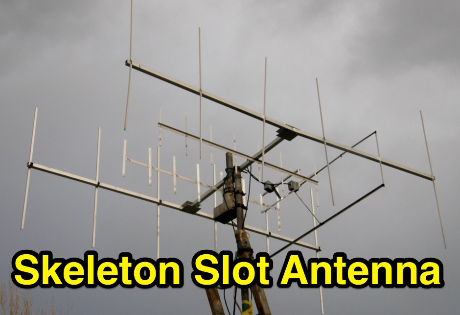 The skeleton slot antenna design was developed in the UK for TV use soon after WW2. This document describe and adapted version for the 2 meter band
 -
 Operating on the 2200m band (135.7-137.8 kHz) often presents challenges for amateur radio transceivers, which typically exhibit poor receiver performance at these very low frequencies. This project addresses the issue by providing a design for a dedicated 137 kHz antenna preamplifier, specifically tailored to improve signal reception for radios such as the _Yaesu FT-817_. The preamplifier circuit utilizes a low-noise FET input stage, crucial for minimizing self-generated noise and maximizing the signal-to-noise ratio from weak LF signals. The design includes a detailed schematic, component values, and construction notes, enabling homebrewers to build a functional unit. The goal is to achieve significant gain, making the faint signals on 2200m more discernible and improving overall band usability. Key design considerations include impedance matching to typical antenna systems and ensuring stable operation across the narrow LF segment. The circuit aims for a **low noise figure** and sufficient amplification to overcome the inherent limitations of general-purpose HF transceivers when operating below **200 kHz**.
 -
 Operating an 80/40/20M fan dipole for DX is analyzed through EZNEC modeling, focusing on the antenna's performance in a real-world, low-height installation. The resource details the physical construction and SWR measurements of the fan dipole, comparing them against EZNEC simulations. It also incorporates High Frequency Terrain Analysis (HFTA) data to illustrate typical DX elevation angles for various regions from New England, providing a crucial context for evaluating antenna patterns. The analysis presents EZNEC-generated azimuth and elevation patterns for each band (80M, 40M, 20M) at specific frequencies, showing gain figures at different elevation angles relevant to DX propagation. It compares the modeled SWR with measured SWR, attributing discrepancies to coax attenuation. The study concludes with observations on the antenna's azimuth performance (omnidirectional within ±1.5 dB) and its less optimal elevation gain at desired DX angles, highlighting the impact of low antenna height on DX capabilities.
 -
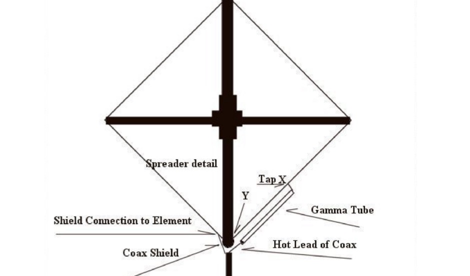 A two meter Quad antenna project with detailed instructions on how to adjust the Quad gamma match
 -
 An Experimental, High-efficiency, Graphic-Tunable Magnetic Loop antenna and loop controller in a 52 pages PDF presentation with drawings and pictures
 -

-
 Calculating HF helical whip antenna for mobile or portable operation
 -
 Sherwood Engineering Inc. (SEI) offers a repository of technical presentations and white papers focused on optimizing amateur radio transceiver and receiver performance. Content includes detailed analyses of _roofing filters_, transmitted IMD, and receiver characteristics, with specific discussions on products like the Drake R-4C and Icom IC-781. Presentations from events such as Dayton Contest University (2008-2014) cover topics like "How To Optimize Rig Performance," "Transceiver Performance: 10 Years of Change," and "Choosing a Transceiver: Far from Simple." Additional white papers address HF mobile antenna efficiency, ground screen alternatives to buried radial systems, and common receiver problems with solutions. The site also provides historical product information for items like the SE-3 MK IV synchronous AM detector and various 455 kHz mechanical and crystal filters, though many products are no longer in production. Receiver test data and alignment tips for the R-4C are also available, offering insights into rig modifications and performance enhancements.
 -
 Guide to ground mounting antennas, notes on efficiency, elevated installations, metal towers and masts, other mounting schemas, moble homes and rv, lightning protections, artiche by Bencher
 -
 The design and feeding of driven elements for VHF/UHF Yagi antennas , modeling, observations and some case studies by Graham Daubney F/G8MBI
 -
 A home made antenna tuner based on the W6JJZ basic concept that ,atches balanced loads without the use of lossy baluns, can provide band-pass filtering and harmonic attenuation.
 -
 This article compares two commercial vertical antennas for the 4-meter amateur radio band: the Watson WVB-70 half-wave and the Sirio CX4-71. The Watson measures 2.03m in length, costs around £40, and exhibited adequate performance but required additional waterproofing after rain affected its VSWR readings. The longer Sirio CX4-71 (3.02m) performed noticeably better, delivering signals approximately 2 S-points stronger than the Watson. The Sirio demonstrated high build quality, a stable 1.2-1.4:1 VSWR, and weather resilience, though minor VSWR fluctuations were observed during rain and frost. Both antennas are half-wave designs requiring no ground plane radials.
 -
 This resource details the four primary functions of a ground system: lightning energy dispersion, equipment safety, RF return path provision for end-fed antennas, and management of induced RF currents. It clarifies that a ground system's effectiveness varies depending on its specific function, noting that a good lightning ground might not be an effective RF ground. The content emphasizes that proper antenna system design, including baluns and appropriate feedline lengths, often negates the need for an RF station ground to mitigate common mode currents or RFI in the shack. The article quantifies lightning energy, stating its peak is in the dozens or hundreds of kilohertz, with damaging energy extending to hundreds of megahertz, and currents reaching thousands of amperes. It recommends solid, wide, smooth copper surfaces for ground leads to achieve low impedance across a wide frequency range. The author, W8JI, shares practical insights from his station, which includes two 300-ft towers and four 130-ft wire verticals, detailing his use of common point grounds and _DX Engineering RR-8 HD_ antenna switches for lightning protection without coaxial surge protectors. Specific examples of antenna systems prone to common mode current problems are listed, such as random wire antennas without proper feedline lengths and off-center fed dipoles. The text also explains how a ground screen or radial system can reduce local noise sensitivity for vertically polarized antennas by covering the lossy earth.
 -
 Decoding NOAA APT weather satellite images is achieved with a homebrew receiver and a Turnstile Cross Dipole antenna, feeding data to a Pentium-3 500MHz PC running Windows XP and the WXTOIMG program. This setup, operated by VU2IIA in Mumbai, India, focuses on capturing and processing signals from NOAA satellites to generate visual weather data. The blog documents the technical aspects of constructing the receiving station, including antenna design and receiver integration. It provides insights into the practical challenges and successes of amateur satellite reception, specifically for Automatic Picture Transmission (APT) signals. Operational details cover the software configuration and image processing workflow necessary to transform raw satellite data into usable weather imagery. The content serves as a practical guide for radio amateurs interested in satellite meteorology.
 -
 Presents a Brazilian online portal dedicated to **amateur radio**, **CB radio**, and shortwave listening (SWL) communities. The platform facilitates free classified advertisements for radio equipment, including HF, VHF, and UHF transceivers, antennas, and accessories. It also aggregates a substantial collection of technical articles from Brazilian amateur radio operators (e.g., PY2DJW, PY1LJ, PY1LL/4LC), covering topics such as CW training with RufzXP, balun importance, and radio wave characteristics. Furthermore, the resource provides extensive links to Brazilian ham radio sites, clubs, international organizations, and official ANATEL (Brazilian National Telecommunications Agency) documents regarding licensing, equipment homologation, and regulations. The portal features sections for user evaluations of transactions, a "Top Ten" list of most visited pages, and a calendar of past and upcoming ham radio events across Brazil, including "Feirinhas" (local swap meets) and "Encontros de Radioamadores" (hamfests). It also includes a directory of ham radio related businesses and services in Brazil, such as antenna manufacturers (Diex), QSL card printers (Arte Final), and repair technicians (PY2MOK). The site also offers propagation maps, DX cluster links (e.g., DX-SUMMIT), and satellite tracking tools, making it a central hub for Brazilian radio amateurs seeking to buy, sell, learn, or connect with the community.
 -
 5-element antenna, with which G0JJL has worked lots of EU crossband, and won the RSGB Christmas Cumulatives 70MHz section twice in a row.
 -
 The Yaesu FT-1000MP Mark-V, introduced at Dayton 2000 Hamvention, features a higher RF power of **200 W PEP** and a Class-A amplification SSB mode at 75 W. Key enhancements include an _Interlocked Digital/Analog Bandwidth Tracking system (IDBT)_, a Variable Front-End Filter (VRF) preselector, and improved ergonomics, notably a multi-function shuttle jog dial. This model, a successor to the 1996 FT-1000 and FT-1000MP, was designed to compete with high-end transceivers, despite its retail price of $4200 initially. The transceiver's physical dimensions are 406 x 135 x 348 mm (16 x 5.3 x 13.7 inches) with a weight of 14 kg (31 lbs), making it substantial. Its rear panel offers over 20 connections, including power, external DSP speaker, BAND DATA I/O, ALC, and multiple interface jacks for DVS-2, Packet, and RTTY. The unit also provides two keyer inputs, a DB9M serial interface for CAT, and two PL female antenna connectors, plus additional receive antenna jacks. Despite its advanced internal architecture, including two independent receivers with their own IF filters and AGC loops, the display technology, utilizing fluorescent discharge rather than LCD, contributes to an older aesthetic. The control panel is extensive, featuring 92 knobs and buttons, alongside numerous LED indicators for various modes and functions.
 -
 This PDF document details the construction of a **70 MHz** Big Wheel antenna, a horizontally polarized omnidirectional array. The design utilizes three full-wave loops, each approximately **2160 mm** in diameter, arranged in a triangular configuration. The resource provides mechanical dimensions for the antenna elements and a comprehensive bill of materials, specifying component quantities and types, such as M8 stainless steel bolts, 15x15x1.5 mm square aluminum tubing for spacers, and 8 mm aluminum rod for the arcs. The central hub is constructed from two 160x160x8 mm aluminum plates, with four 40 mm long polyamide insulators supporting the radiating elements. The feed system incorporates a 50 mm diameter aluminum pipe for mounting and a matching stub constructed from a 120x20x2 mm aluminum sheet, connected via M8x10 mm bolts. The resource includes a diagram illustrating the mechanical dimensions and assembly points, including the N-connector fixing point and the center conductor attachment. The project was published on May 25, 2011, by Peter OE5MPL and Rudi OE5VRL. DXZone Focus: PDF | 70 MHz Big Wheel | Mechanical Dimensions | **2160 mm** loop diameter
 -
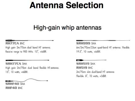 The document titled 'Extending the Range of Your Handheld' by WG7S is a guide on how to extend the range of your handheld VHF UHF transceiver by using an external antenna. It provides information on comparing popular models, selecting the right antenna, and resources for amateur radio antennas.
 -

-

-
 The performance of a small magnetic loop can be improved constructing it larger, thicker or both. The antenna is covering from 12 Megahertz to 32 megahertz and adding a 156 Pico farads ceramic capacitor it resonates on the 40 meters band. by PY1AHD
 -
 80 to 6 meters, 2 KW, designed to be used at heights of only 25 to 45 feet, includes a twenty foot long vertical radiator
 -
 The X80 multi-band HF vertical antenna, a commercial iteration of the Rybakov design, exhibits a physical length of 5.5 meters, or approximately 18 feet, and is constructed from aluminum tubing. It operates as a non-resonant vertical, requiring an external antenna tuner for impedance matching across its intended operating frequencies. The antenna's design incorporates a 1:4 UNUN at its base, facilitating a nominal 50-ohm feed point impedance for the coaxial cable. Performance observations indicate effective operation on 40 meters, 20 meters, 15 meters, and 10 meters, with reduced efficiency on 80 meters and 160 meters due to its relatively short electrical length for these lower bands. Comparative analysis with a G5RV dipole and a half-wave end-fed antenna reveals the X80 offers a lower take-off angle, beneficial for DX contacts, particularly on the higher HF bands. Field tests conducted with an Icom IC-706MKIIG transceiver and an LDG AT-100ProII autotuner demonstrate the X80's ability to achieve acceptable SWR across 80m through 10m. The antenna's compact footprint and ease of deployment make it suitable for restricted spaces or portable operations, though its performance on 80 meters is noted as a compromise compared to full-size resonant antennas.
 -
 The ZS6BKW multi-band antenna, an optimized variant of the classic G5RV, is presented with detailed construction and tuning instructions. This resource outlines the antenna's design principles, which were developed by _Brian Austin (G0GSF)_ using computer programs and Smith charts to achieve optimal dimensions. It provides specific guidance on calculating and adjusting the lengths of the radiators (L1) and the matching ladder line (L2), emphasizing the critical role of velocity factor (VF) in achieving resonance. The article includes a step-by-step procedure for empirically determining the VF of ladder line using an antenna analyzer, ensuring accurate physical lengths for the matching section. It details the tuning process for the radiators, offering practical tips for incremental adjustments to achieve the best SWR curve. The resource presents SWR measurement results obtained with an _AIM-4170C_ analyzer across multiple bands, alongside predicted SWR graphs from an AutoEZ model. It confirms successful contacts on 80, 40, 20, and 17 meters, including a **17-meter DX contact** to Italy. EZNEC and AutoEZ models for the ZS6BKW antenna, covering 80 through 6 meters, are provided for download, allowing further analysis and customization. The document specifies component details, such as the use of Wireman 554 ladder line and #14 AWG THHN copper wire, and discusses the antenna's performance characteristics, noting high SWR on 15 and 30 meters but successful tuning on 6 and 80 meters with an external tuner.
 -
 In this PDF article Zack Lau describe how to homebrew a four element yagi beam antenna for 50 MHz band, including how to build mounting blocks and tubing clamps to hold elements.
 -
 Manufacturing distributor of infrastructure products for the telecommunications industry; antenna mounts, ice bridge, cable ladder, ground bars, weatherproofing, exothermic, safety equipment.
 -
 Demonstrates various practical amateur radio projects and technical discussions through video episodes. One episode details cutting and retuning a _1/4 wave shorted stub_ from 101.7 MHz to 107.5 MHz to safeguard a transmitter's driver stage, alongside insights into advanced _160-meter antenna systems_ like eight-circle arrays and beverage antennas. Another segment covers upgrading firmware on an _ATS-20+_ receiver using AverDudes for improved display and functionality, and a detailed guide on using D-Star DR mode on an _ICOM ID-52A_ for international repeater programming. Additional content includes a deep dive into _OpenHamClock_ as a potential replacement for the HamClock project, updates on _Raspberry Pi 5_ running Trixie OS, and a review of the Choyong LC90 Internet radio with AI integration. The series also features "Ham College" episodes, which meticulously prepare viewers for the Technician Exam by covering topics such as antenna and transmission line measurements, SWR interpretation, and the functions of basic electronic components like rectifiers, relays, and transistors. Practical advice on coaxial cable characteristics, dummy loads, and proper soldering techniques is also provided.
 -
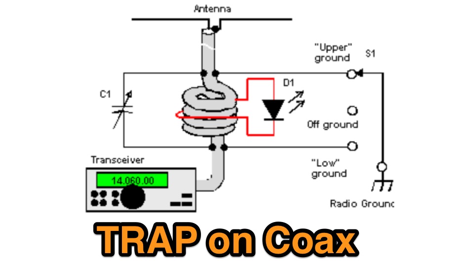 A trap on the coaxial cable, also known as choke, helps to eliminate the sneaking of the reflected RF- energy to the shack. The trap can be made from the coaxial cable that feeds the antenna
 -
 Dimensions and EZNEC plots for a 2 Element 30 meter Yagi antenna with 28 Ohm featuring 4.3 dBd Gain and a 16dB F/B with a good bandwidth.
 -
 Protecting amateur radio equipment from transient overvoltages requires robust lightning and surge protection, which is the focus of Electronic Specialty Products. The company provides various devices, including coaxial lightning arrestors for antenna feedlines and surge protectors for AC power lines and data circuits. These devices are engineered to divert high-energy surges, such as those caused by direct or indirect lightning strikes, away from sensitive transceivers, amplifiers, and computer components, thereby preventing catastrophic damage. Key products include the _Coaxial Lightning Protector_ series, designed for various impedance levels and frequency ranges up to 3 GHz, and the _AC Line Surge Protector_ for shack power distribution. Effective deployment of these protection devices can significantly reduce the risk of equipment failure and ensure operational continuity during severe weather. For instance, a properly installed coaxial arrestor can handle peak currents of **20 kA**, while AC line protectors offer clamping voltages typically below 400V. Comparing different models reveals varying levels of insertion loss and return loss, with some coaxial units exhibiting less than 0.1 dB loss at 500 MHz, making them suitable for high-performance HF and VHF/UHF operations. Integrating these components into a comprehensive grounding system is crucial for achieving maximum protection against both common-mode and differential-mode surges.
 -
 Crank-up(telescopic) and tilt-over tower, Ring rotator for mounting an extra antenna, from 16m to 42m, Strong safe and smooth, Radio communication and commercial tower.
 -
 Demonstrates the operational status and reception reports for the SK6RUD/SA6RR QRPP beacons, which transmit on 478.9 kHz, 1995 kHz, 10.131 MHz, and 40.673 MHz. These beacons utilize extremely low power, with the 630-meter beacon operating at approximately 0.1 watt ERP into an L-antenna, showcasing the potential for long-distance contacts under favorable propagation conditions. The site details the specific frequencies and antenna types employed, such as a vertical at 500 kHz and a 1/4 vertical for higher bands. The resource compiles over 10,530 reception reports from amateur radio operators worldwide, logging details such as date, time, band, RST signal report, locator, distance, and receiver setup. Notable long-distance reports include a 500 kHz reception by AA1A-Dave from 5832 km in 2008 and a 10.133 MHz reception by ZL2FT-Jason from 17680 km in 2010, illustrating the global reach of these low-power transmissions. Each log entry provides specific equipment used by the reporting station, including transceivers like the Yaesu FT817, ICOM IC-7300, and various antenna configurations such as coaxial mag loops, inverted Ls, and end-fed wires. The primary objective of the SK6RUD beacons is to challenge conventional notions of power requirements for effective two-way communication, proving that contacts over significant distances are achievable with minimal output. The site also includes a submission form for new reception reports, fostering community engagement and continuous data collection on propagation phenomena across different bands. The detailed logs offer practical insights into real-world propagation characteristics and the efficacy of QRPP operations.
 -
 Examines the historical role of telegraphy within Canadian railway operations, detailing the evolution of communication systems crucial for train dispatch and coordination. It covers the technical substance of railway telegraphy, including equipment, operational procedures, and the personnel involved, such as agents and operators. The resource provides insights into the **F59PH locomotive** history, development, and components, alongside diagrams of various parts like antennae and traction motors. The content also explores the practical application of these systems by documenting specific railway events, such as the CPR Galt Sub operations from 1895-1971 and GO Transit's operational history. It includes photo galleries, schematics, and diagrams of locomotives and cab cars, offering a visual and technical comparison of different railway equipment. The site also features information on **GO Transit** rolling stock, including MP40s and commuter coaches, providing a historical context for railway communication and transportation.
 -
 Examining the _Angle of Radiation_ and its impact on amateur radio operations, the resource provides insights into optimizing antenna performance for DX and local contacts. It features a design for SPOTTO, a direct conversion high-performance universal DSB transceiver, detailing its construction and operational characteristics for homebrew enthusiasts. Additionally, the site presents a 7-element VHF high-gain antenna design, offering practical schematics and expected performance metrics for those seeking enhanced gain on VHF bands. The resource also covers the development and popularity of the _FT8_ digital mode, highlighting its effectiveness in weak-signal conditions and its role in special event operations like the FT8DMC anniversary. It includes information on Hamfest India 2023 and the Lamakaan Amateur Radio Convention, providing dates and organizational details for significant Indian amateur radio gatherings. Technical articles on Direct Digital Synthesizers (DDS) VFOs and low-cost multifunctional frequency counters offer practical project ideas for radio amateurs.
 -
 The TiltPlate is an antenna tilting mechanism that works with a tilt over tower and yagi to bring the antenna all the way down to ground level.
 -
 An improved version of DK9NL QRM Killer, with dedicated noise sampling antenna for completely filtering of plasma TV rattle on HF bands