Search results
Query: 7 element antenna
Links: 430 | Categories: 3
-
 An easy to build and extremely high performance antenna, works perfectly on all HF bands 3.5-28 MHz with some compromises, it is basically an half wave dipole for 40-80 meters, an LC circuit or trap 40 meters allows you to use a single radiating element.
 -
 Three Yagi antennas for the six meters band by 9A7PJT. Include a 4 element yagi, a custom design 4 element, and a 5 element yagi with antennas pictures and design.
 -
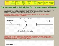 The construction principles for open-sleeve elements in antennas
 -
 This article is about a 4 element yagi VHF antenna designed to be easy to be assembled and suited for portable operations
 -
 A 7 dB directional gain is reported for this portable VHF Yagi antenna design, which utilizes cut metal tape measure sections for its elements. The resource details the construction process for a 2-meter band antenna, emphasizing its ease of build and portability. It specifically mentions the design's suitability for radio direction finding (RDF), fox hunting, and communication with satellites and the International Space Station (ISS), highlighting its practical applications for amateur radio operators. The construction cost is estimated at under $20, with potential for even lower expense if salvaged materials like old tape measures and PVC pipes are used. The article references _Joe Leggio's_ (WB2HOL) original design, noting specific alterations made by the author. It also compares this design to other DIY Yagi antennas, including _FN64's_ 2-meter band and _manuka's_ 70-cm band tape measure Yagis, underscoring its unique combination of simplicity, portability, and effective performance with a 1:1 SWR achievable on the 2-meter band.
 -
 1.5 dB of matched line loss can be calculated for a given transmission line using this online tool, which employs a model calibrated from empirical data. The calculator allows radio amateurs to input specific transmission line types, such as _RG-8_ or _RG-58_, and then determine the expected signal attenuation. This is crucial for optimizing antenna system efficiency and understanding power delivery to the radiating element, especially for HF and VHF operations where feedline losses can significantly impact performance. Beyond matched loss, the calculator also provides an estimate for mismatched loss if the Standing Wave Ratio (SWR) is specified. This feature helps operators quantify the additional power loss due to impedance discontinuities between the transceiver, feedline, and antenna, which is a common concern in amateur radio installations. Accurate loss calculations are vital for effective station design and for predicting actual radiated power. The tool's utility extends to various operating scenarios, from fixed station setups to portable deployments, aiding in the selection of appropriate feedline lengths and types to minimize signal degradation. Understanding these losses is a fundamental aspect of maximizing the effectiveness of any amateur radio antenna system.
 -
 This 6 meter 2 element yagi antenna is simple, compact and effective antenna for 50 Mhz. The design antenna was optimized with AO for best match to 50 ohms, no matching network. A choke balun is recommended to decouple feedline currents.
 -
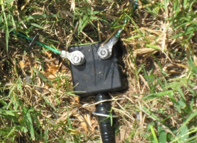
 This web article details the construction of a 4-meter band coaxial dipole antenna, designed for operation between **70.000 MHz and 70.500 MHz**. The resource provides a bill of materials and step-by-step assembly instructions for a half-wave dipole constructed from _RG-58_ coaxial cable. The design specifies a direct 50 ohm feedpoint impedance, eliminating the need for an external matching network. Construction photographs illustrate the stripping and soldering processes for the coaxial cable elements, ensuring proper electrical connection and physical integrity. The article includes specific dimensions for the radiating elements, derived from calculations for the 70 MHz band. The project outlines the physical dimensions required for resonance at 70 MHz, with the outer braid forming one half and the inner conductor forming the other. The feedline connection is directly to the coaxial dipole's center, maintaining a 50 ohm characteristic impedance. While the article does not present SWR plots or VNA sweeps, it focuses on the mechanical construction and dimensional accuracy for achieving a functional 4-meter dipole. The design is intended for fixed station use, with no specific mention of polarization or height above ground, but implies a standard horizontal orientation for dipole operation. DXZone Focus: Web Article | 4m Coaxial Dipole | Construction Guide | 50 ohm Feed
 -
 An article describing how to homebew a VHF 4 elements Yagi antenna.
 -
 A delta loop antenna for 20 meters band designed with MMana with a tuning system made in a classic stub configuration
 -
 An interesting presetnation full of usefull tricks to correctly design and build 23 cm Yagi using simple tools. The basic design of the antenna presented in this document is taken from the original DL6WU Yagi Design published in 1982
 -
 Pictures, design plan and description of a 5 element yagi antenna for the 4 meters band by 9A7PJT
 -
 YT1VP Yagi antenna for 6 meters
 -
 K1JJ presents a compilation of insights regarding vertical radial ground systems, specifically applied to 160m vertical arrays. The resource details 19 distinct observations and recommendations, emphasizing that ground radials primarily reduce ground losses rather than influencing pattern formation. It explains that RF current flows inefficiently through average soil, necessitating copper radials to create a low-resistance path back to the antenna base. The content suggests that **50-60 radials** are generally sufficient to achieve optimal efficiency, with diminishing returns beyond that number, and that radials should be laid on the surface for best performance. The discussion also addresses practical aspects such as wire gauge, installation techniques using 'U' shaped staples, and methods for connecting radials in multi-element arrays. It highlights the importance of radial length, stating that 1/4 wave radials are a crucial minimum, and that for 160m, radials should be at least _100 feet_ long. The resource critically examines the efficacy of elevated radials versus ground radials, noting that while a few elevated radials may suffice for VHF, HF applications, particularly on 160m, require extensive ground radial systems to efficiently collect RF currents in the near field. It also touches on the impact of radial systems on parasitic elements and the significance of symmetrical radial patterns for minimizing losses. Further practical advice includes wire type recommendations, proper soldering and weatherproofing techniques for radial connections, and considerations for integrating steel towers into the ground system. The author shares personal experience with installing 60 quarter-wave and half-wave radials under each of three in-line verticals, expressing satisfaction with the results.
 -

-
 A home made 4 element yagi antenna that can be easily adapted for 10 meter band
 -
 A six meter band 3 element yagi beam antenna project with shortened elements using coax cables with the outer ends stripped and the center conductor shorted in somewhat of a Bazooka antenna.
 -
 Rotatable Antenna with Phased Elements based on the orignal design concept of HB9CV antennas, is considered to have an higher gain than standard quad antennas. The Swiss Quad Antenna does not need any spreader or boom.
 -
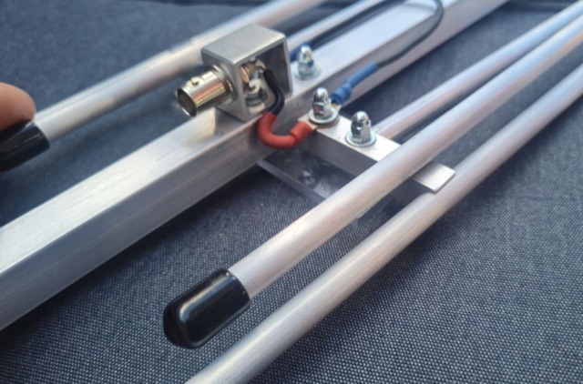
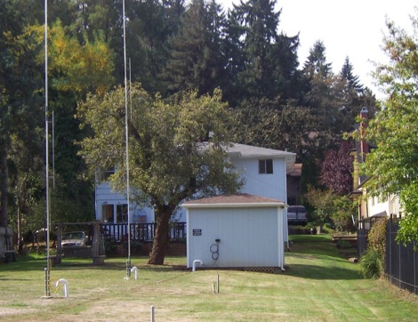
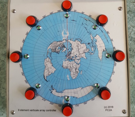 The receiving antenna setup for the top band, made with a 9 elements vertical antenna array, remote controller and remote relais.
 -
 The webpage discusses metal fatigue in antenna elements for radio amateurs, offering construction tips and techniques. It covers theory, tricks, and the use of baluns and coils.
 -
 A great and efficient monoband VHF portable antenna. The article consist of two version of a 12.5 Ohm 3 elements yagi beam antenna plans for the two meter band, a full sized and a shortened version expecially designed for the SSB and CW on 144 MHz.
 -
 A 2 elements yagi beam for 12 meters band with liear load
 -
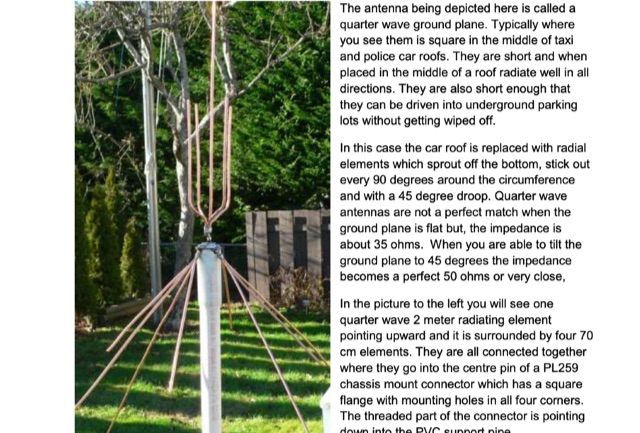 Adapted from a similar project by NA4IT. Made with one quarter wave 2 meter radiating element pointing upward and it is surrounded by four 70 cm elements.
 -
 A light and sturdy Quad for 10 and 15 meters. Basic Quad antenna design considerations. Building and assembling a dual band HF QUAD antenna, designing and joining cross-arms and boom, assembling spreader and element wire installation notes. QST article.
 -
 A two element beam antenna for ten meters band. This home-brew two-element beam is the perfect introduction to rolling your own gain antenna
 -
 The Maria Maluca HF multiband antenna as designed in 1957 by PY2BBP is a directive antenna for 15 meter and a passive element that works as director and reflector in different bands
 -
 A compact high G/T Yagi with bent Drive element by DG7YBN
 -
 Presents _Beam Quest_, the official Japanese distributor for _SteppIR_ antennas, detailing their product lineup and services. The site showcases various _SteppIR_ Yagi models, including the _Dream Beam_ series (DB42, DB36, DB18E, DB11) with configurations from two to four elements, alongside the _Big IR_ and _Small IR_ vertical antennas. It also lists accessories such as TX/RX and PC interfaces, essential for integrating these advanced antenna systems into a ham shack. Operators often seek out _SteppIR_ antennas for their dynamically adjustable element lengths, which allow for optimization across multiple bands, a significant advantage for DXing and contesting. This adaptability contrasts sharply with fixed-element Yagis, providing a distinct edge in varying band conditions. The resource provides contact information, including email and phone numbers, for inquiries and support regarding _SteppIR_ products within Japan, serving as a direct point of contact for sales and technical assistance.
 -
 A practical guide on hombrewing Yagi antennas, including notes on Driven Element, Transformation & Symmetrising Coax Lines, Full Boom length vs. electrical length, Elements & Insulators on Boom and additional tips and tricks, in English and German
 -
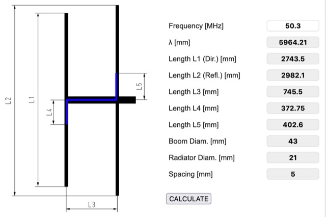 Online HB9CV antenna calculator, accept as input the desired resonating frequency and provides dimensions for spacing and length of each element, including boom and radiator diameter.
 -
 The calculator designs the Yagi-Uda antenna based on the DL6WU model with boom correction, following the G3SEK-DL6WU method. It optimizes the antenna for maximum gain and allows adjustment of passive elements without affecting SWR. DL6WU antennas are known for their high gain, minimal sensitivity to nearby objects, and stable performance in various weather conditions.
 -
 Building the Three-Element Hex Beam. A project and construction phase of an HF hex-Beam antenna using trees to hang the antenna and a Channel Master antenna rotator.
 -
 Designing and constructing a two-element receiving loop antenna array for HF operation involves specific considerations for achieving high directivity and noise reduction. This resource details a homebrew system comprising two 30-inch diamond-shaped loops, spaced 20 feet apart, which are fed through mast-mounted preamplifiers and passive signal combiners. The operational principle relies on adjusting phase delays between elements via precise _Belden 8241_ coaxial cable lengths, optimized for specific bands from 160m to 20m. Performance data, derived from _EZ-NEC_ modeling, illustrates consistent 90° azimuth-plane beamwidth and low take-off angles across the target bands, with _Receiving Directivity Factor_ (RDF) values comparable to a 300-foot Beverage antenna. The article presents detailed elevation and azimuth plots for 20m, 30m, 40m, 80m, and 160m, demonstrating the array's ability to provide strong response at low DX angles while also supporting _NVIS_ signals. Key components like the _DX Engineering RPA-1_ preamplifier and _DXE RSC-2_ signal combiner are discussed, alongside the importance of impedance matching to preserve antenna patterns. The construction emphasizes self-contained elements that do not require ground radials, offering a compact solution suitable for suburban environments and stealth installations, with a focus on optimizing receive performance independently from transmit antennas.
 -
 A 70 cm yagi antenna design by YU7EF includes tables with antenna elements dimension and spacing. This UHF Yagi antenna plan provides a maximum gain of 17.93 db
 -
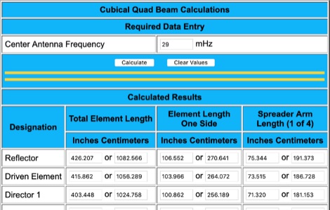 Cubical Quad Antenna On-line Calculator helps on defining the size of each element and spreader. Simply give the resonating frequency and it will calculate size of each element.
 -
 An experimental antenna for HF reception. It consists of a single loop element mounted on the ground. It is stealthy, small, and quiet. EZ-NEC plots and on-air test results are included.
 -
 Constructing an End-Fed Half-Wave (EFHW) antenna offers a practical solution for HF operators seeking a multiband wire antenna without the need for extensive radial systems. This design typically employs a high-impedance transformer at the feed point, matching the antenna's inherent high impedance to a 50-ohm coaxial feedline. The article specifically details a 2012 approach, focusing on a transformer with a 49:1 turns ratio, which is a common configuration for EFHW antennas. The resource outlines the construction of a wire element cut for a half-wavelength on the lowest desired band, with specific coil arrangements enabling operation on harmonically related bands such as 40m, 20m, and 10m. It discusses the physical dimensions and winding details for the matching transformer, often utilizing a ferrite toroid core to achieve the necessary impedance transformation. The content provides insights into the operational principles and practical considerations for deploying such an antenna, including methods for tuning and optimizing performance across multiple amateur radio bands. While acknowledging that the presented information from 2012 may be superseded by newer insights, it serves as a foundational reference for understanding EFHW antenna theory and construction.
 -
 Quads beams consist of 2 1 wavelength (approximately) loops, ordinarily arranged so that one is the driven element and the other is the reflector. In this project author explains how to build a two element Quad Antenna for the 28 MHz.
 -
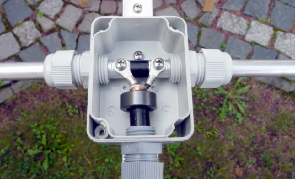
 One of the featured products, the V350 CAMP, is a multiband vertical antenna covering 6 to 80 meters, priced at R$ 799,90, demonstrating the range of ready-to-use solutions available. The inventory includes various antenna types such as **HF**, **VHF**, and **UHF** designs, along with dual-band options like the J-Pole Dual V/UHF for R$ 235,00. For those building their own arrays, the store stocks essential components like element holders, clamps, junction boxes, and aluminum plates, alongside specialized items such as the KIT Isolador Central Dipolo - 01DX for R$ 99,90. The shop also provides a comprehensive selection of installation hardware, including diverse antenna mounts, PTT supports, and various coaxial cables like RG58 and RG213, with prices up to R$ 849,90 for RG213. Connectors such as UHF male PL259 and various adapters are readily available, ensuring compatibility for different setups. Additionally, specialized items like side handles for popular transceivers such as the FT857/891 and IC7300 are offered, catering to specific equipment needs. Beyond antennas, the store supplies practical accessories like transport bags, 12V power cables for transceivers, and even branded merchandise like the Antena Kit mug. Rodrigo Gonçalves, PP5BT, manages the operation from Blumenau, SC, Brazil, providing direct contact via WhatsApp at +55 47 9.9985.0155.
 -
 A 20-meter window frame stealth antenna, based on a design by _PD7MAA_, utilizes a single 620cm wire loop for discreet installation. The feeding mechanism employs a _4C65_ toroidal core, where the antenna loop functions as a single-turn secondary, and the feedline wraps twice. Tuning is achieved via a 30cm twisted wire stub, allowing for SWR adjustment within the 20m band. This design is specified for QRP operation, with a maximum power limit of **25 Watts** to prevent core saturation or arcing. Wire selection recommendations include thin, insulated copper wire (0.75mm to 1mm) for blending with architectural elements. The guide focuses on practical construction steps for a low-profile 14MHz antenna.
 -
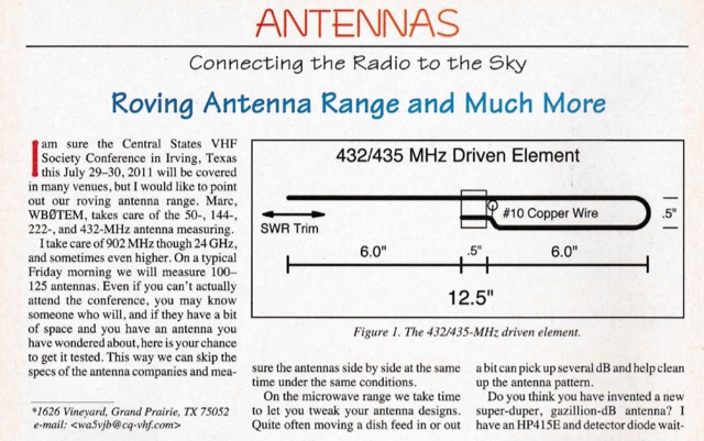 A 18 elements Yagi antenna for 432/435 MHz as published on 2011 CQ VHF magazine
 -
 Make them simple then Make them work. The LAZY H antenna is a general type of antenna that is in the curtain array family. By placing two 1 wavelength dipoles in a plane that is at right angles to the direction of maximum radiation and keeping the proper in-phase current condition to each element, you can achieve a high gain bi-directional antenna.
 -
 The Tri-pole antenna, a clever modification of a standard dipole, allows for dual-band operation by integrating a third element. This design effectively shortens the overall dipole length by 10 to 20 percent, simplifying antenna rotation and offering a compact footprint. KK4OBI's article delves into the operational principles, using a 6 and 10-meter Tri-pole as a primary example, and provides comprehensive instructions for constructing any Tri-pole antenna within the 6 to 15-meter range. Key to the Tri-pole's performance is its off-center feed, necessitating a common mode choke at the feed point for optimal tuning and reduced noise. The author outlines a methodical approach to determining element dimensions, starting with a vertical element frequency calculated as 0.47 times the sum of the desired upper and lower band frequencies. This calculation, along with K-values derived from trend lines, guides the initial lengths for the horizontal arms, demonstrating how a 10m-6m Tri-pole can achieve a total horizontal length 78% shorter than a conventional 10-meter dipole. Tuning and balancing are critical, with the article detailing adjustments to arm lengths and the vertical element to achieve balanced SWR values, as validated through 4NEC2 simulations. Radiation patterns are analyzed at various elevations, showing gains around 5.7 dBi and favorable take-off angles for DX contacts. Construction details specify aluminum tubing dimensions, U-bolts, and an SO-239 connector, emphasizing the importance of a ferrite-based choke for wideband operation.
 -
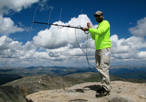 An attempt to build a 2m antenna. Consist of a 4 element yagi antenna for SOTA activities
 -
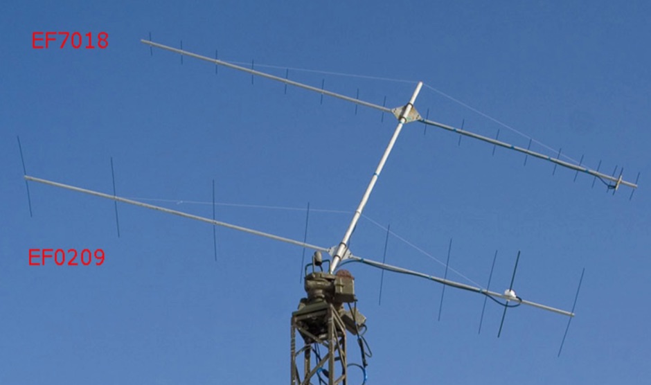
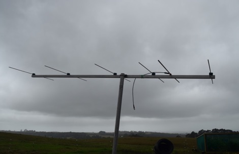
 Antennas for the 1296 MHz based on the construction plans of some Yagis 35 elements by DL6WU, F9FT, DJ9YW. These antennas features a boom of about 3 m and gives a gain of about 17.8 dBd
 -
 A basic YAGI UDA online antenna calculator, accept as input frequency, number of elements, diameter of parasitic element and boom diameter. This online calculator will generate a basic design data including each element length and spacing.
 -
 YU7EF EF0206 2m Band 6 Element Yagi Antenna project, provides 11.8 dbi gain
 -
 A home made RDF 3 elements Yagi that can be used for fox hunting. The particularity of this antenna is that it can be folded, in order to save space while travelling. In Dutch.
 -
 A review of the 30 meter MonoGap Antenna. This review covers from the unboxing go the Gap product, the assembly of the elements, the test and tuning phase and a performance report during the years
 -
 The DIY 137 MHz WX SAT V-dipole antenna project details the construction of a specialized antenna for receiving weather satellite transmissions. It provides specific dimensions for the dipole elements, designed for optimal reception around the 137 MHz band, which is commonly used by NOAA and Meteor weather satellites. The resource outlines the materials required, such as aluminum tubing for elements and PVC for the support structure, along with the necessary coaxial cable and connectors. The article presents a clear, step-by-step assembly process, including how to form the V-shape and connect the feedline. It emphasizes practical considerations for mounting and weatherproofing the antenna for outdoor deployment. The design focuses on simplicity and effectiveness for amateur radio operators interested in satellite imagery. Key aspects include the precise angle of the V-dipole and the lengths of the radiating elements, which are critical for achieving the desired circular polarization response for satellite signals. The resource includes photographic documentation of the construction phases and the final mounted antenna.