Search results
Query: 2 meter net
Links: 470 | Categories: 2
-
 This calculator ask as input diameter, lenght turn and frequencu and will return L and Q
 -
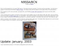
 Beacon website of WE4S, Grady Donaldson, located in McDonough, GA. EM73TM.
 -
-
 Demonstrates the construction of a high-power 6-meter (50 MHz) amplifier, specifically designed for demanding modes like EME, TEP, and multiskip Es. It details the use of a _GU-43B_ tetrode in a grounded-cathode configuration, emphasizing the need for stabilized grid voltage and input capacitance compensation. The resource provides a comprehensive schematic, power supply design, and practical considerations for component sourcing, particularly for high-voltage and high-current sections. The builder achieved an output power of **1250 watts** with an anode current of 0.65 amperes and 3200 volts anode voltage. The article also covers the physical construction within a modified P6-31 enclosure, outlining the internal layout for RF and power supply sections, and includes photos of the completed unit. It highlights critical safety precautions for working with high voltages and reactive currents up to **20 Amperes** in the P-network.
 -
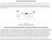 This generator requires 100volts supply at 5mA. A 0 -5 mA meter inserted at J1 measures the crystal current.
 -
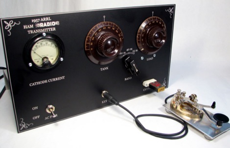 A homebrew radio transmitter project, based and inspired by the original 30 Watts input on 80 50 and 15 meters band transmitter by W11CP
 -
 Sixty-meter repeaters typically use a 1 MHz frequency separation between input and output, while 2-meter repeaters commonly employ a **600 kHz** split and 70-centimeter repeaters use a **5 MHz** offset. This article details the fundamental technical principles of amateur voice repeaters, explaining how they extend VHF/UHF communication range by receiving on one frequency and simultaneously retransmitting on another. It covers essential components such as receivers, transmitters, filters, and antennas, often situated on elevated locations for optimal coverage. The resource delves into the critical challenge of _desensing_—where the repeater's strong transmit signal overpowers its own receiver—and the engineering solutions employed, including antenna separation and the use of high-Q cavity filters. It also explores various control and timing systems, from basic squelch activation to more sophisticated microcontroller-based boards that manage functions like voice identification, time-out timers, and fault protection. Different access methods are discussed, including open access, toneburst, CTCSS subtone, and DTMF, each offering distinct advantages for managing repeater usage and mitigating interference. Furthermore, the article examines repeater linking, both conventional RF methods and modern internet-based solutions, highlighting how linking expands coverage and promotes activity across multiple repeaters or bands. It introduces less common repeater types such as 'parrot' repeaters, which use a single frequency and digital voice recording, and linear translators, capable of relaying multiple signals and modes simultaneously across different bands, often found in amateur satellites.
 -
 Constructing a basic multimeter involves integrating a 0-1mA meter movement with various shunts and multipliers, selected via a switch, to create a versatile instrument capable of measuring DC volts, current, and resistance. The design outlines two main units: a primary unit handling six DC current ranges up to 1 amp and eight DC voltage ranges up to 1000 volts, alongside an internal battery for an ohms range up to 200,000 ohms. This approach allows for a practical, hands-on understanding of meter operation. An add-on unit further extends the multimeter's capabilities, incorporating a meter rectifier and switched series resistors to provide four AC voltage ranges up to 100 volts. Additional shunt and series resistors, designated Ra and Rb, are included to expand the instrument's range to 10A and 5kV, demonstrating how modular design can enhance functionality. When this add-on is in use, the main instrument is set to measure 1mA FSD, connecting via specific lugs. Component selection emphasizes precision, with 1% tolerance high stability resistors for series elements and Eureka resistance wire for shunts. The design specifies values calculated for a meter with 60 ohms internal resistance, noting that these would require modification for different meter characteristics. Experimental adjustment of shunt values is recommended to ensure accurate readings against a calibrated reference meter, reinforcing practical calibration techniques.
 -

-
 Sort of similar to the one of the 6m omni. Instead of using twin-lead, this design makes use of a more or less regular double bazooka antenna (coaxial dipole). Your attention shall be drawn to the available standart literature, such as Rothammel. In order to "compute" the dimension, Karl Rothammel mentioned that the total length of the dipole shall be 95% of the free-space wavelength. The short-circuit bridges (closing the folded dipole) are to be placed at a distance-fraction being equal to the velocity factor of the coax cable used, which will be 66% using RG-58 or RG174.
 -

-
 Developing operational amateur radio equipment for the 134 GHz band presents significant technical challenges, particularly in frequency generation and stability. This resource details the construction of a 134 GHz system, outlining its architecture with separate transmit (Tx) and receive (Rx) modules, each employing a local oscillator (LO) and RF head units. The system utilizes a dual Flann 50 GHz lens-type horn antenna configuration for optimal signal coupling. The transmit path incorporates an LMX2541 synthesizer chip operating at approximately 2.8 GHz, referenced by a 10 MHz double-oven Morion OCXO for exceptional stability. This signal is multiplied through a series of stages (X4, then X2) to generate a 22.4 GHz signal, which subsequently drives a dual series diode multiplier to produce the final X6 signal for 134 GHz operation. The receive side features an anti-parallel diode mixer coupled to a 144 MHz transceiver via a preamplifier, ensuring effective downconversion. Operational mode is CW, achieved by keying a multiplier stage. The project includes images of the Tx and Rx head units and describes a successful 3.5 km test with G8ACE, demonstrating stable signal tones due to PLLs locked to OCXOs at both ends, confirming the system's robust performance.
 -
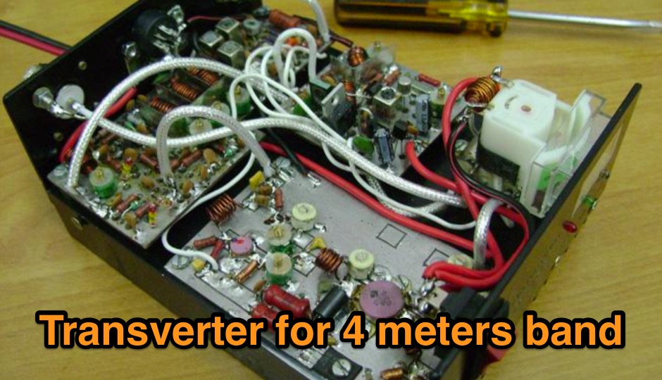 A 70 MHz Transverter project with a block diagram and schematics
 -

-
-
 The RBN S-Meter visualizes real-time HF propagation data from the Reverse Beacon Network (RBN). It processes thousands of automated spots per hour, providing a real-time picture of active RF paths on HF bands. Users can set their vantage point using _Region Mode_ or _Grid Square Mode_. Region Mode allows selection from broad geographic areas like E. North America or Europe, while Grid Square Mode uses a Maidenhead grid square and radius for more precise data. The app displays eight region panels, each with horizontal bars for bands 160m through 6m, indicating signal strength with a color ramp from green to red. A dimmer trail shows peak hold values, and an S-unit readout provides additional detail. The app is a free web application accessible on any device, offering a practical tool for ham radio operators interested in CW, RTTY, and FT8 signals. It features a Progressive Web App installation option for enhanced usability on mobile and desktop platforms. Users can install it on Android, iOS, and Windows devices, providing a native app-like experience. The app replaces the previous Windows standalone executable, incorporating user feedback to improve features like grid square mode and automatic location detection.
 -
 Modifying an MFJ-259B Antenna Analyzer to operate on 630 meters
 -
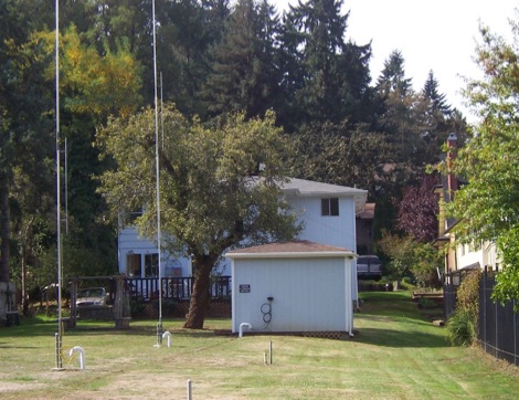
 The Boone Area Radio Klub (BARK) serves Boone County, Iowa, as its local amateur radio club, actively welcoming visitors to its meetings and weekly ARES nets. The club maintains a 2-meter repeater on 146.850/250 MHz with a 114.8 Hz tone and a 440 MHz repeater on 443.9+ MHz, both situated at the Boone County Hospital, with a simplex fallback on 146.550 MHz for the 2-meter net. Additionally, BARK supports the Iowa 160-meter ARES net at 1.972.5 MHz, which operates at 9:30 PM on Sundays, featuring a rotating schedule of net controls including KNØR, KBØMPL, NØISU, KEØQEU, and KBØLPI. BARK conducts bimonthly license testing sessions on the second Saturday of even-numbered months, with specific dates like October 19, 2024, at the Hamboree, requiring a $15 fee and prior FCC Registration Number (FRN) acquisition. The club's activities are well-documented through numerous photo galleries from past Field Days (1998, 1999, 2008, 2010, 2013, 2017, 2018, 2019), JOTA events (2013), and special event stations (2010 B&SVRR&M). Members like KBØMPL (Margot Conard) have contributed educational PowerPoint presentations on topics such as "Fun with Handie Talkies," "HF Propagation," and "Digital Mode - FLDIGI - OLIVIA 8/500 - JT65 HF - BAND PLANS." The club's officers, as of May 2018, include WØFS (Clay Conard) as President, NØISU (Mitch Carroll) as Vice-President, and KBØLPI (Eric Sloan) as Treasurer/Secretary, guiding the club's operations and community engagement.
 -
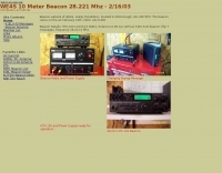
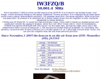
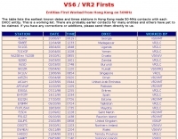
 The ZS1J/B beacon operates on 28.2025 MHz with 5 Watts output to a half-wave, end-fed vertical antenna, initially installed in 1977 as ZS5VHF near Durban. The 10-meter transmitter is a modified 23-channel CB radio, and the identification keyer uses a diode matrix unit with TTL ICs from the same era. After relocation to Plettenberg Bay in 1993, the beacon has been in continuous service, with additional QRP transmitters later installed for other bands. In 1994, a single-transistor, 80-meter, 0.5-watt QRP transmitter with a half-wave dipole was added on 3586 kHz, followed by a 160-meter, 0.5-watt unit on 1817 kHz. A 30-meter, 0.5-watt transmitter was installed in 1996, operating on 10.124 MHz. In 2002, a 40-meter QRRP beacon on 7029 kHz, with an output of 100 microwatts, achieved DX reports up to 1100 km from ZS6UT in Pretoria. Best DX reports for the 80m and 160m beacons came from 9J2BO.
 -
 Over 150 pages of content are dedicated to maximizing activity on the 6-meter band, often referred to as the _Magic Band_. The resource details various propagation modes, including sporadic E, F2, and tropospheric ducting, providing insights into their characteristics and how to leverage them for DX contacts. It also covers essential equipment considerations, from transceivers and transverters to specific antenna designs optimized for 50 MHz operation, such as Yagis and Moxon antennas. The eBook presents strategies for participating in 6-meter contests and pursuing awards like _VUCC_, offering practical advice on logging software and operating techniques. It includes discussions on software tools useful for predicting propagation and managing contacts, alongside guidance on finding and utilizing DX maps to identify openings. The author, K5ND, shares his extensive experience to help operators achieve successful 6-meter DXing. Specific sections address the code of practice for 50 MHz operations and provide assistance in locating rare DX opportunities. The content is structured to guide both new and experienced operators through the nuances of the band, from initial setup to advanced operating strategies.
 -
 Low-frequency (LF) radio time signals, operating primarily in the 40–80 kHz range, are broadcast by national physics laboratories for precise clock synchronization. Transmitters like **JJY** (40 kHz, 50 kW; 60 kHz, 50 kW), RTZ (50 kHz, 10 kW ERP), MSF (60 kHz, 15 kW ERP), WWVB (60 kHz, 50 kW ERP), RBU (66.66 kHz, 10 kW), and DCF77 (77.5 kHz, 50 kW) cover vast geographic areas, often several hundred to thousands of kilometers. LF signals offer distinct propagation advantages over higher-band transmissions such as GPS. Their long wavelengths (3–6 km) enable effective diffraction around obstacles like mountains and buildings. The ionosphere and ground act as a waveguide, eliminating the need for line-of-sight and allowing a single powerful station to cover extensive regions. Ground wave propagation minimizes ionospheric variability effects on transmission delay, and signals penetrate most building walls effectively. Robust and low-cost receivers, often priced at 20–30 USD/EUR, are widely used in radio clocks. These receivers typically comprise a tuned ferrite core antenna, a receiver IC (e.g., Atmel T4227, U4223B, MAS1016) for amplification and AM detection, and a microcontroller for decoding the time signal and phase-locking a local clock. Specific components for DCF77, MSF, and WWVB are readily available from vendors like HKW Elektronik and Ultralink.
 -
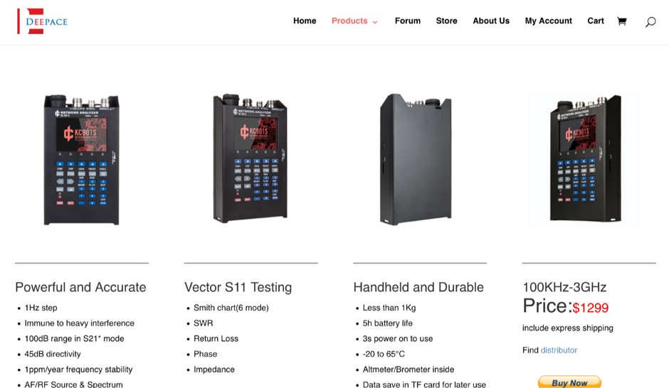 KC901S Handheld vector antenna analyzer RF ANALYZER 3GHz S11 S21 Fieldmeter RF Source Spectrum
 -
 Operating an amateur radio club, VE2CEV details its activities, including regular meetings and a significant project involving the construction of a **satellite ground station**. The resource outlines the project's inception, team formation, equipment acquisition, and the physical installation of antennas and rotator systems. It specifically mentions the use of a dual-axis AZ/EL rotator and antennas for VHF, UHF, and SHF (2 meters, 70 centimeters, and 13 centimeters), along with the strategic use of **Heliax cables** to minimize RF signal loss. The club also provides information on its interconnected repeater network covering southwestern Montérégie. The content highlights the practical application of the satellite station for communicating via amateur satellites and the International Space Station (ISS). It details the collaborative effort of members in securing a powerful Linux server, negotiating antenna installation with local authorities, and the precise alignment of antennas. The club emphasizes its role in guiding new amateurs, offering demonstrations, and potentially organizing courses, indicating a focus on community engagement and technical education within the amateur radio hobby.
 -
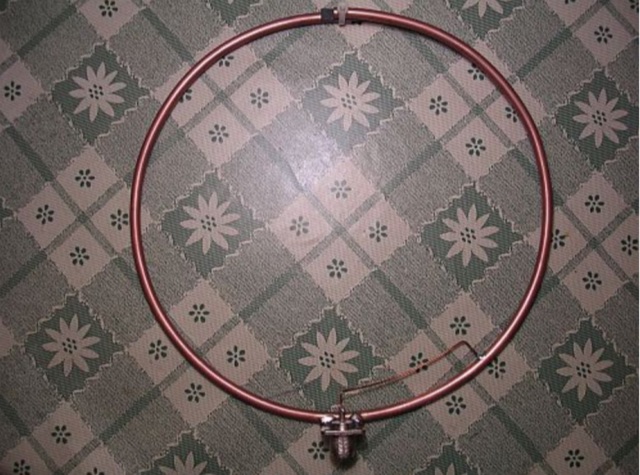 A small, easy to build, copper tube magnetic loop antenna for the 2 meters band. In Italian
 -
 Basic magnetic loop antenna examples and loop aerials theory explained. This article inclued some interesting tricks on building magnetic loop antennas and an usefull excell sheet to help compute magneti loop antennas calculating power efficiency from 10 to 40 meters band
 -
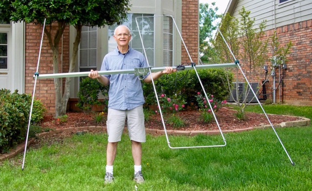
 The Tri-pole antenna, a clever modification of a standard dipole, allows for dual-band operation by integrating a third element. This design effectively shortens the overall dipole length by 10 to 20 percent, simplifying antenna rotation and offering a compact footprint. KK4OBI's article delves into the operational principles, using a 6 and 10-meter Tri-pole as a primary example, and provides comprehensive instructions for constructing any Tri-pole antenna within the 6 to 15-meter range. Key to the Tri-pole's performance is its off-center feed, necessitating a common mode choke at the feed point for optimal tuning and reduced noise. The author outlines a methodical approach to determining element dimensions, starting with a vertical element frequency calculated as 0.47 times the sum of the desired upper and lower band frequencies. This calculation, along with K-values derived from trend lines, guides the initial lengths for the horizontal arms, demonstrating how a 10m-6m Tri-pole can achieve a total horizontal length 78% shorter than a conventional 10-meter dipole. Tuning and balancing are critical, with the article detailing adjustments to arm lengths and the vertical element to achieve balanced SWR values, as validated through 4NEC2 simulations. Radiation patterns are analyzed at various elevations, showing gains around 5.7 dBi and favorable take-off angles for DX contacts. Construction details specify aluminum tubing dimensions, U-bolts, and an SO-239 connector, emphasizing the importance of a ferrite-based choke for wideband operation.
 -
-
 Basically, this antenna is a 23-foot wire fed through a 4:1 un-un transformer. This antenna can be easily used in portable operation, for operating all bands from 40-10 meters.
 -
 Top Loaded Vertical Antenna 3,5 MHz 80m and a 14 MHz Trap for the 20m band. The weight of this portable vertical antenna is less than 1 kg, including the ground network. The weight of the telescopic fiberglass fishing rod is another 1kg. The rod expands from 1.5 meters to 8 meters.
 -
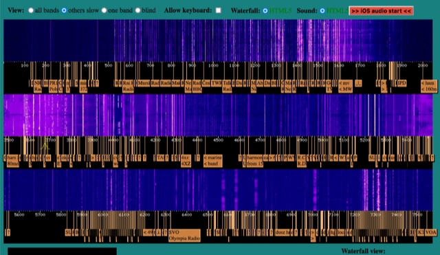 WebSDR receiver located near Krizevci, Croatia with 0-2 MHz, 60-80 meters band and 40-49 meters band
 -
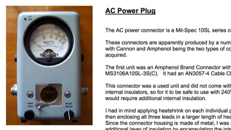 Bird 4314 RF Power Meter Battery Replacement
 -
-
 DF0WD/DL4YHF's Longwave Overview details amateur radio operations on the 135.7 to 137.8 kHz segment in Germany. The author outlines the "inofficial" European band plan, specifying segments for QRSS, TX tests, beacons, conventional CW, and data modes. Early LF activities at DF0WD began with a 20-watt CW transmitter, later upgraded to a homemade linear transverter capable of 100 watts, driven by an Icom IC706 on 10.137 MHz. The station's antenna system includes a 200-meter wire, approximately 10 meters above ground, supported by football field light-masts. Despite its length, the antenna's efficiency is noted as very low due to the immense wavelength of about 2.2 km. The author's experience highlights the significant challenge of achieving effective radiated power (EIRP) on LF, estimating DF0WD's EIRP at around 80 milliwatts based on field strength measurements from PA0SE. DF0WD/DL4YHF has successfully worked numerous countries on 136 kHz CW, including DL, F, G, GI, GM, GU, GW, HB9, HB0, LX, OE, OH, OK, OM, ON, OZ, PA, and SM. The author also mentions ongoing efforts to log contacts with CT, EI, LA/LG, and to complete a two-way QSO with Italy, demonstrating persistent activity on this challenging band.
 -
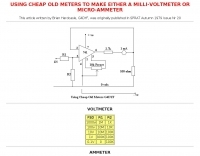 This article include a circuit that allows a cheap 0-1mA meter to be used as a micro-ammeter or a milli-voltmeter
 -
 AC7GZ/B is a converted Sharp CB-2460 Citizens Band transceiver operatin on 28.2118 MHz.
 -
 A review of the 30 meter MonoGap Antenna. This review covers from the unboxing go the Gap product, the assembly of the elements, the test and tuning phase and a performance report during the years
 -
 The ARRL's End-Fed Half-Wave (EFHW) Antenna Kit is an easy-to-build four-band antenna designed for 10, 15, 20, and 40 meters. Ideal for portable operations, it includes a 49:1 impedance transformer for compatibility with most transceivers. This project, detailed with step-by-step assembly instructions, involves creating a weatherproof enclosure and impedance matching network. The kit simplifies HF operations and supports multiple configurations, making it a versatile tool for amateur radio opertors.
 -
 Clarifies the intricate process of calibrating the _Elecraft K2_ dial, addressing common user challenges and lively discussions on the Elecraft reflector. Wilhelm, W3FPR, dissects the K2's PLL synthesizer design, chosen for its low phase noise, kit-friendly duplication, and cost-effective components. The resource emphasizes the critical role of the 4000.000 kHz reference oscillator's accuracy during CAL PLL, CAL FIL, and CAL FCTR functions, noting its dependence on temperature and crystal stability for optimal performance. Explaining the K2's frequency display, the document reveals it relies on microprocessor-driven look-up tables generated by CAL PLL for VFO values and CAL FIL for BFO values. In SSB and RTTY, these combine, while CW and CWr modes also factor in the sidetone pitch. The author details inherent limitations, such as the 10 Hz increment resolution of the dial and varying PLL step sizes—from 3 Hz on 160 meters to 10 Hz on 10 meters. BFO increments range from 20 to 35 Hz, collectively limiting practical dial accuracy to within **20 Hz** with diligent effort, or **30 Hz** for a slightly less demanding task. The guide outlines a four-step calibration procedure: setting the reference oscillator, running CAL PLL, running CAL FIL, and setting all BFOs. It highlights the _N6KR Method_ as a particularly easy and accurate approach, requiring only the K2 and a known frequency source like WWV for zero-beating, eliminating the need for external test equipment.
 -
 256 memories enable the _AT-AUTO_ to recall settings across multiple bands, making it efficient for operators who frequently change frequencies. The tuner is compatible with various antennas and amplifiers, such as the Mercury LUX, and integrates seamlessly with radios like the FLEX 6400 using an RS232-USB connection. This integration allows the tuner to follow frequency changes without additional input, enhancing operational efficiency. Despite being out of production, the _AT-AUTO_ remains supported by Kessler Engineering, which offers firmware updates and repair services. The tuner features a cross-needle SWR meter, providing quick visual feedback during tuning. It also includes a QRO keyline circuit to protect amplifiers during tuning. Users appreciate the tuner's ability to track radios via CAT control, avoiding automatic tuning during QSOs, a common issue with other models. The _AT-AUTO_ is praised for its durability and performance, with many users noting its reliability over years of use. Its ability to handle legal limit power and its balanced line output make it a versatile choice for serious operators. Although it lacks some features like multiple coax outputs found in other models, its robust build and continued support make it a valuable tool for HF enthusiasts.
 -
-
 Determining the characteristic impedance (Z) of an unknown coaxial cable, a common challenge for many radio amateurs, can be resolved with a straightforward method. The impedance of a coaxial cable is derived from its inductance and capacitance, and importantly, these values are independent of the cable's length or the operating frequency. This means that measuring a random length of cable, such as 20 meters, provides sufficient data for calculation. The core of this technique involves an LC-meter to obtain the inductance (L) in microHenries (uH) and capacitance (C) in microFarads (uF). The impedance is then calculated using the formula Z = L/C. For instance, a measurement yielding L=1.2uH and C=450pF (0.00045 uF) results in an impedance of 51.6 Ohms, closely matching **RG-58** specifications. Similarly, a TV coaxial cable with L=1.8uH and C=320pF (0.00032 uF) calculates to 75 Ohms. While the accuracy of this method, depending on the LC-meter's tolerance, is approximately 10%, it proves sufficiently precise for practical determination of unknown coaxial cable impedance, as noted by Makis, SV1BSX, who credits Cliff, K7RR, for the formula's dissemination.
 -
 N4PAL 10 Meter, 28.214MHz Radio Beacon Site Information and Siginal Report Logging
 -
 Constructing a dual-band antenna for 40 and 20 meters often involves compromises in size or complexity. This resource presents a compact _open sleeve dipole_ design that addresses these challenges by using 450-ohm ladder line and folded elements to achieve a total length of approximately **17.17 meters**, significantly shorter than a full-size 40-meter dipole. The design leverages electromagnetic coupling, where a primary radiator handles the 40-meter band, and a second conductor resonates on 20 meters without direct electrical connection. This configuration eliminates the need for traditional traps, loading coils, or switching components, simplifying construction and reducing potential loss points. The antenna is fed with RG-58C/U coaxial cable, and a common-mode choke is recommended at the feed point to suppress sheath currents, ensuring a cleaner radiation pattern and minimizing RF in the shack. The design is well-suited for portable operations, field deployments, temporary installations, and restricted urban environments where space is a premium, offering solid performance on both HF bands.
 -
 Getting Started on the Magic Band is a very exaustive article about operating the six meters band. It covers several aspects of operations, techniques, tips and guidelines on getting started on the six meters band.
 -
 A magnetic loop antenna designed for 14 MHz. This kind of antennas is also known as STL, small transmitting loop and can be an excellent solution when you are not allowed to put antennas on your roof
 -
 A 3 band dipole antenna for 40-80-160 meter bands, It's made with easily available materials and is designed for inverted V mounting. The antenna is shortened for these bands, but still manages to make contacts in 80m and 160m with stations in Canada and the USA. The construction details are provided, including the dimensions of the antenna elements and the traps. The antenna is easy to build and provides good performance in all three bands. In Italian.
 -
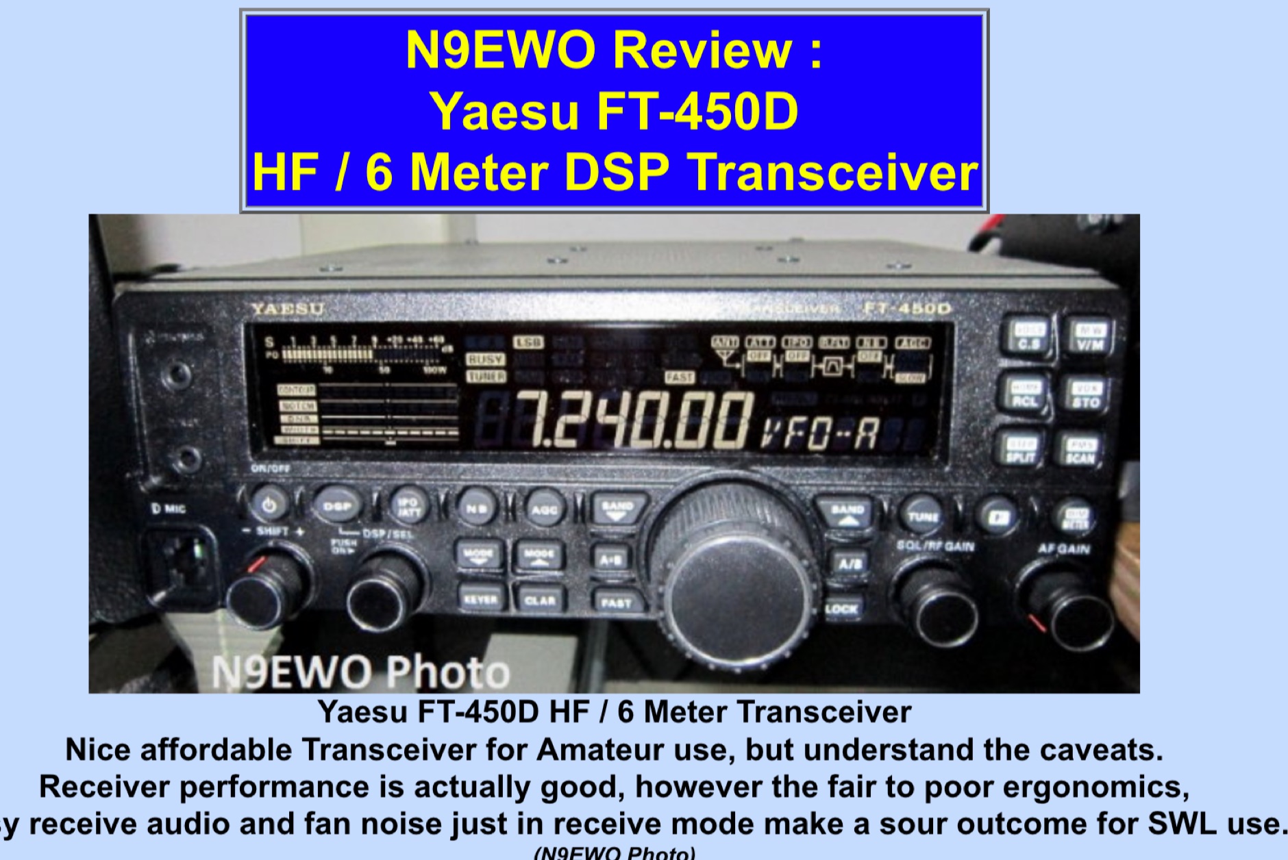 Yaesu FT-450D HF / 6 Meter DSP Transceiver, a nice affordable transceiver for amateur radio use, but understand the caveats.
 -
-
 Jeri Ellsworthhas started a video series devoted to building a magnetic loop antenna for the 160- and 80-meter bands. The first video, included after the break, is an overview of the rationale behind a magnetic loop
 -