Search results
Query: calcul
Links: 381 | Categories: 14
Categories
- Antennas > Antenna Calculators
- Technical Reference > Calculators
- Software > Antenna analysis
- Antennas > Theory > Antenna Gain
- Technical Reference > Attenuators
- Antennas > Bazooka
- Operating Aids > Distance & Bearing
- Software > EME
- Software > Grid Bearing and Maps
- Operating Aids > Grid Squares
- Antennas > HB9CV
- Software > RF Design
- Technical Reference > Components > Toroids
- Antennas > Theory > Wind Load
-
 This program simplifies the complex jumper calculations for the PRF1520 radio, which can be a pain to determine manually. It supports common crystal frequencies and channel spacings, advising if a desired frequency is achievable. A recent feature allows determining unknown frequencies of a newly obtained radio by setting the jumper positions and other parameters.
 -
 Online impedance calculators grouped by types like Wire inductances, Toroid incuctances, Plane, PAD, Strap inductances, but even Core and Coax Inductances. Air core inductances and mutual inductance groups are also availbale. All these calculators let you input specific paramenters based on the inductor selected and will calculate specific incutance and related dimensions.
 -
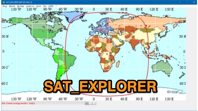 SAT_EXPLORER is a versatile software for tracking the Moon, Sun, and artificial satellites while controlling various antenna interfaces. Compatible with Windows XP and later (32/64-bit) and multilingual (English, French, German, Italian, Spanish), it integrates seamlessly with TRX-Manager for transceiver control. SAT_EXPLORER computes satellite and Moon positions with high precision, calculates EME Doppler shifts, and uploads real-time satellite positions and coverage maps to your personal web pages. Linux/Ubuntu users can run it using WINE or CROSSOVER.
 -
 The DIY Power Meter project utilizes the _INA226_ high-side power monitoring chip, paired with an ATtiny85 microcontroller, to measure voltage, current, and power, displaying the results on a 128x32 OLED screen. The INA226 communicates via an I2C interface and is programmed with a calibration factor based on the shunt resistance and current register LSB. The project is designed to handle a maximum current of 500mA using a 0.16ohm shunt resistor, which can be adjusted to a 0.2ohm resistor, reducing the full-scale current range to 409mA with a resolution of **12.5uA**. The shunt resistor dissipates only 33mW at maximum current, making 1/4 watt resistors suitable for the setup. The PowerMeter.ino sketch configures the shunt resistance and maximum design current, automatically calculating the calibration factor. The project can be prototyped on a breadboard using an Arduino Uno, employing the Wire library for INA226 and OLED communication, and the u8g2lib library for the OLED display. For the ATtiny85 version, the Adafruit-TinyWireM and Tiny4kOLED libraries are used. The power meter is independently powered by a 3V CR2032 cell, with power switching options including manual switches or DC switched jacks. The low-side n-channel MOSFET switch configuration is tested but introduces voltage drop issues, making manual switching a more reliable option until a suitable DC switched jack is found. DXZone Technical Profile: INA226 | ATtiny85 | OLED Display | Power Meter
 -
 Online antenna calculator for J-Pole models.
 -
 Delta loop antennas, particularly the 30 meter variant, offer unique advantages in terms of vertical polarization and omni-directional coverage. The construction process detailed by VE3VN highlights common mechanical and electrical challenges faced by amateur radio operators. Key design considerations include minimizing interaction with existing contest band antennas, achieving low elevation angles for DX chasing, and ensuring the antenna remains off the ground for agricultural clearance. The article provides specific measurements, such as the loop's height and feed point impedance, which are critical for optimizing performance. The use of NEC modeling software illustrates the importance of accurate resonance calculations, revealing how proximity to the tower affects both pattern and impedance. This practical account serves as a resource for hams looking to build effective antennas while navigating typical construction hurdles.
 -
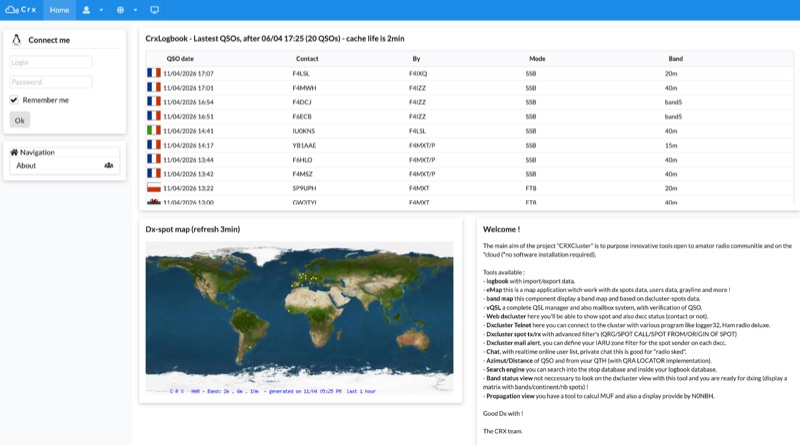 Demonstrates a cloud-based suite of tools for amateur radio operations, eliminating local software installation. The platform integrates a comprehensive logbook with import/export functionality, an _eMap_ application displaying DX spots, user locations, and grayline data, alongside a dynamic band map derived from DX cluster information. It also provides a _vQSL_ system for QSL management and a mailbox with QSO verification. Users can access a Web DX cluster to monitor spots and _DXCC_ status, or connect via Telnet using external programs like _Logger32_ or Ham Radio Deluxe. The cluster supports advanced spot filtering by QRG, spot call, spot from, and origin, with configurable mail alerts based on IARU zone filters. Additional features include a real-time chat for skeds, azimuth/distance calculations from a user's QTH (with QRA locator), a search engine for spot and logbook databases, a band status matrix, and a propagation tool for MUF calculations, leveraging data from N0NBH.
 -
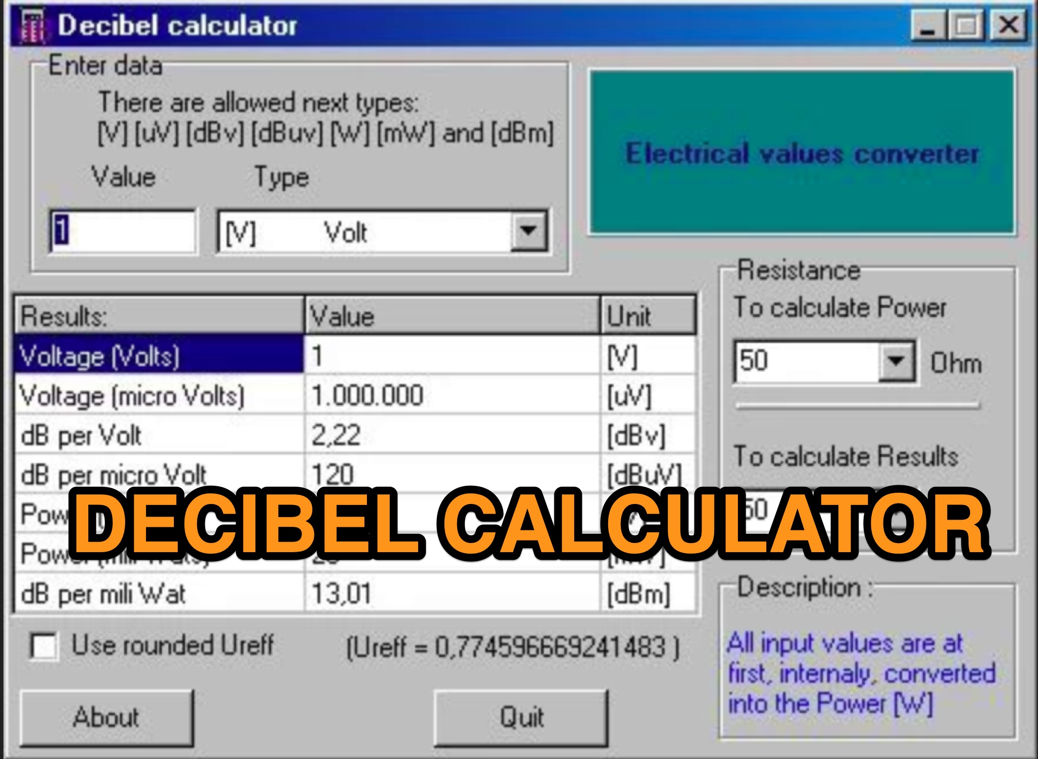 Learn how to easily convert between different units like dBu, dBm, W, mW, V, and uV with the dBCalc application. This small windows program allows ham radio operators to quickly check conversions using input and output resistance. It's a useful tool for anyone dealing with electronic measurements and calculations. Best of all, dBCalc is free to use, making it a convenient solution for amateur radio enthusiasts. This tool simplifies complex conversions and helps hams optimize their equipment setup.
 -
 This article explores the powerful features of AutoEZ as an Excel application working with EZNEC antenna modeling software. The article demonstrates how variables, equations, and formulas enable versatile antenna design and automatic optimization. Through practical examples including dipoles, inverted vees, delta loops, and monopoles, the author shows techniques for achieving resonance, implementing transmission line resonators for broadbanding, and optimizing antennas across frequency ranges. The step-by-step demonstrations cover unit conversion, coordinate calculations, segmentation considerations, and SWR optimization. This practical guide illustrates how AutoEZ extends EZNEC's capabilities, making complex antenna modeling more efficient and accessible.
 -
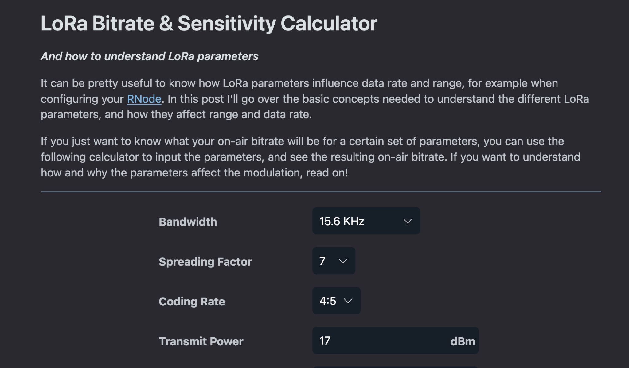 This article explains how LoRa parameters impact data rate and range when setting up a LoRa transceiver. It covers the basic concepts needed to understand different LoRa parameters and their effects on modulation. By adjusting parameters, you can achieve fast data transfers or extend transmission range. The post also offers a calculator to determine on-air bitrate based on input parameters. Understanding LoRa parameters is crucial for optimizing performance and achieving desired communication outcomes.
 -
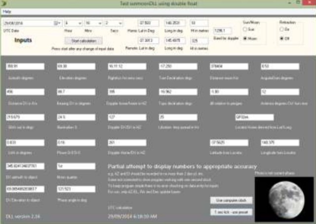 The purpose of the Moon tracking DLL is to provide an easily used platform for the calculation of the position of the sun or the moon and to provide the associated information often required for amateur radio operators interested in EME. DLL works with any of Windows versions of Delphi, Visual Basic, C and versions.
 -
 This excel workbook addresses the issue of power loss in transmission lines with complex characteristic impedance ZoZo​. It illustrates the discrepancy between actual loss (0.35 dB) and matched line loss (0.6 dB) using a simplified example, highlighting potential software tool limitations. The RF Feedline Power-Loss Calculator provides accurate end-to-end loss assessments for both microwave and RF applications. This tool is suitable for engineers and students and is compatible with Windows versions of Excel 2016 or later, though it is not compatible with Macintosh systems.
 -
 The Beam project offers various features for controlling antenna rotators, including support for 2 or 4 line LCD displays, software or hardware clocks, open collector drives for azimuth and elevation control, and internal calculations for tracking the sun and moon. It can also track satellites and supports "Flip Mode" for inverted antennas. The 4-line version provides detailed readouts while the 2-line version offers a more compact display. New versions now support PWM and I2C H-bridge modes for adjustable speed control at the end of a move.
 -
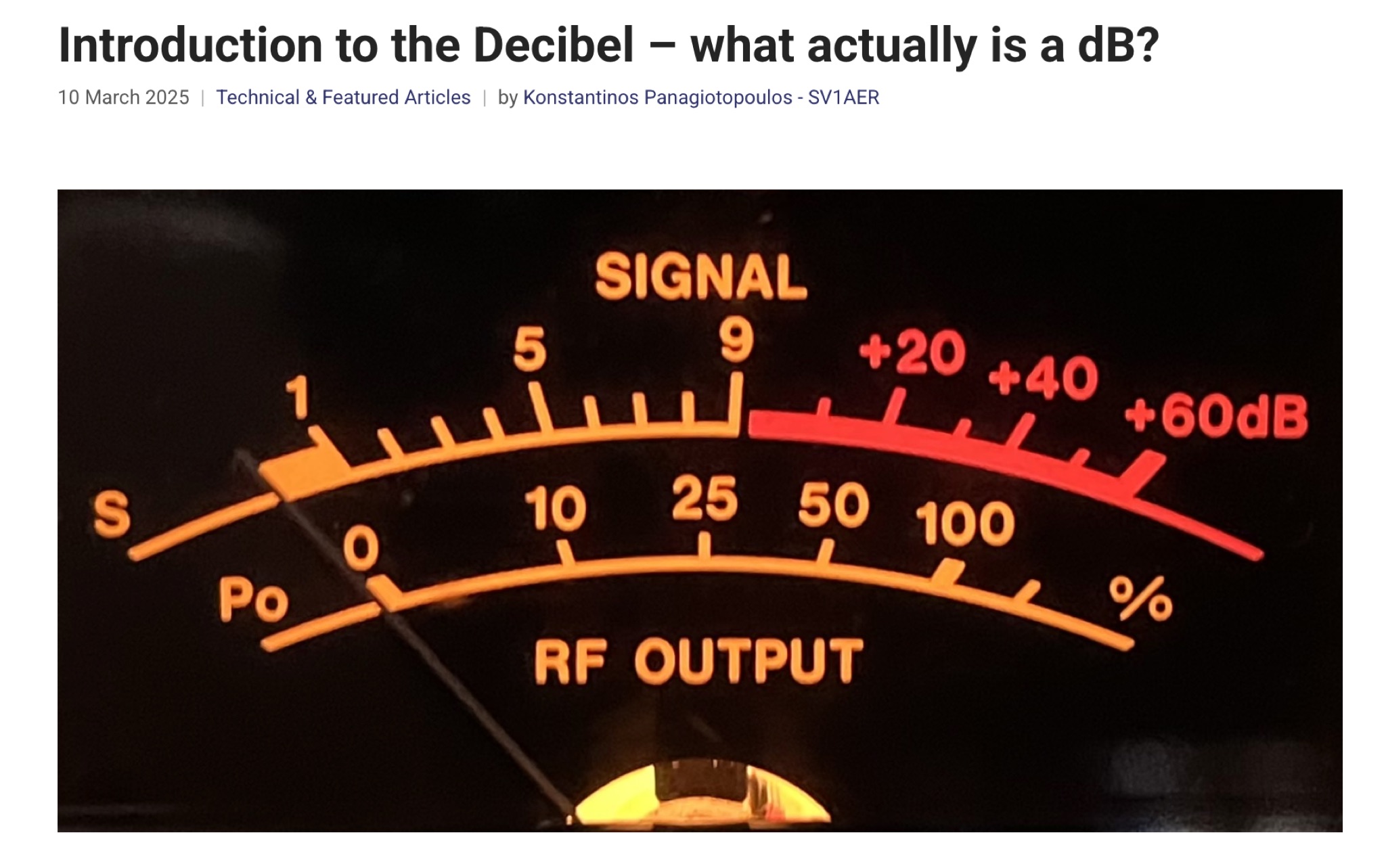 This article provides a comprehensive introduction to the decibel (dB), its logarithmic nature, and its applications in power, voltage, and antenna gain calculations. It explains how dB simplifies comparisons in electronics, telecommunications, and audio perception. The author clarifies key mathematical concepts, including power ratios, voltage doubling, and absolute levels like dBm and dBV. The discussion on S-units and antenna system gain is particularly relevant for radio amateurs. Overall, this is an informative and well-structured guide to understanding and applying decibels in technical fields.
 -
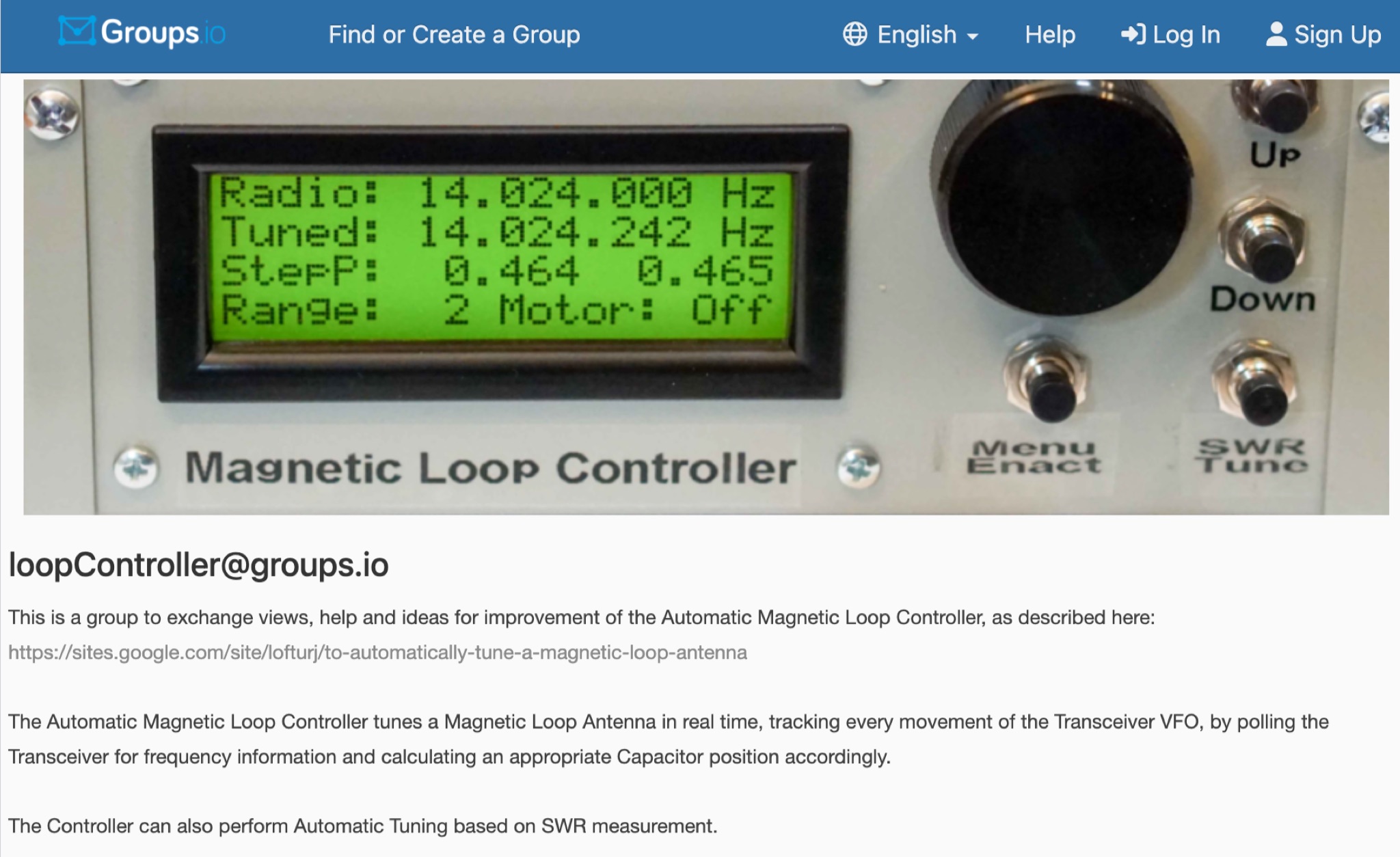 This is a group to exchange views, help and ideas for improvement of the Automatic Magnetic Loop Controller, as described at VE2AO web site. The Automatic Magnetic Loop Controller tunes a Magnetic Loop Antenna in real time, tracking every movement of the Transceiver VFO, by polling the Transceiver for frequency information and calculating an appropriate Capacitor position accordingly. The Controller can also perform Automatic Tuning based on SWR measurement.
 -
 A full-wave delta loop antenna, approximately 141 feet in total wire length for the 40-meter band, offers a low angle of radiation, which is highly advantageous for DX operations. This design, optimized for both 30m and 40m, leverages a specific circumference calculation of 1005/F, ensuring resonance on both bands through a simple switching mechanism. The antenna's configuration enhances long-distance communication, making it a practical choice for hams with limited space. The resource details the construction process, including the use of a _Ceramic Knife Switch_ for band selection and an _RG-11_ matching section to achieve optimal impedance. It outlines the precise loop lengths required for each band, along with tuning secrets to ensure efficient operation. Requiring a minimum height of 12 feet, this antenna can be supported by a single mast or tree limb, making it suitable for suburban installations where stealth or space constraints are a factor.
 -
 This project outlines a simple, cost-effective 40m band HF dipole antenna design, ideal for beginners. Constructed with insulated copper wire and a 1:1 balun, it offers a 50-ohm impedance, suitable for both 40m and 15m bands due to the harmonic relationship. Calculations account for a K factor, ensuring optimal length and performance. Antenna modeling with 4NEC2 confirms practical access to both bands, though real-world results may vary. Lightweight materials and straightforward assembly make it an accessible and versatile amateur radio solution.
 -
 Online Coil Inductance Calculator. To calculate the inductance of a single-layer, air-core coil, just select the measurement units, enter the number of turns, the coil diameter and the coil length.
 -
 This page by ARCTICPEAK provides a calculator for determining ERP and EIRP (Effective radiated power and effective isotropic radiated power). The tool is designed to help hams calculate and understand the power radiated by their radio equipment. The content is useful for ham radio operators who want to optimize their transmission power and comply with regulations. LA8OKA Martin has created this resource to assist hams in accurately measuring their radio signals.
 -
 This page calculate and compared visual the difference between the farnsworth timing speed and the standard morse timing.
 -
 This article explores the role of velocity factor (VF) in calculating stub lengths for VHF/UHF Baluns. It clarifies misconceptions about VF's relevance, distinguishing between coaxial cable interior fields and external stub fields. Practical examples, such as the Pawsey Stub and Coaxial Cable Balun, are analyzed alongside experimental findings. The results reveal that traditional VF adjustments are unnecessary for stubs with external fields but critical for internal coaxial applications. Historical and theoretical insights provide a comprehensive perspective for antenna enthusiasts and designers.
 -
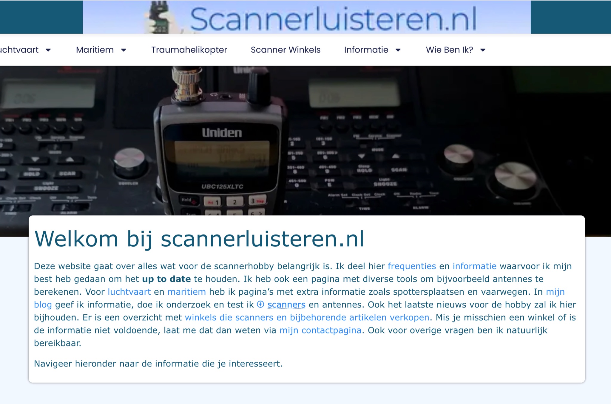 A Dutch website, with a translation option, about scanner radios, maritime, and aviation communication. With maps,a blog, free tools and calculators, and a large collection of Dutch frequencies.
 -
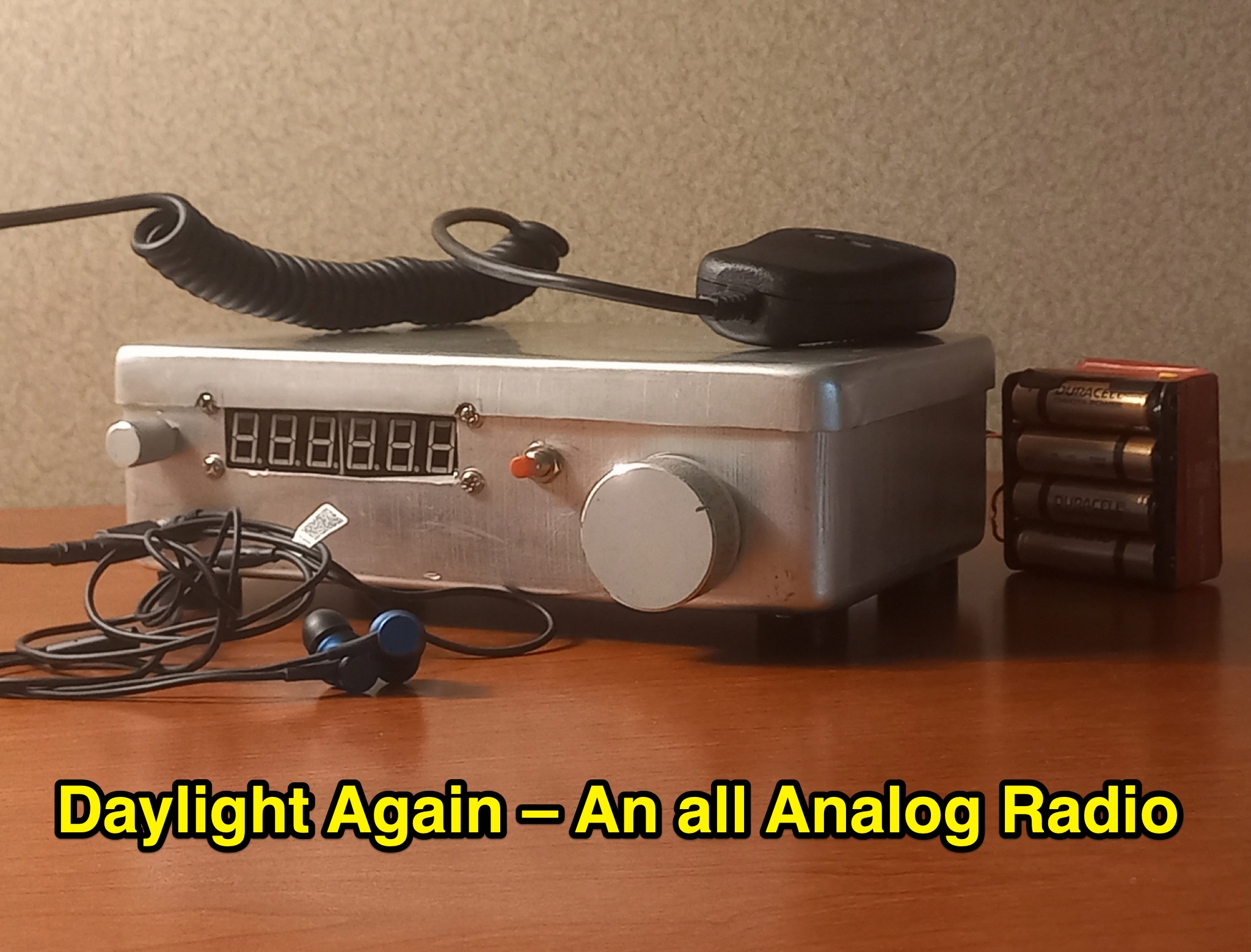 This article discusses a high performance, 7MHz, 5 watt SSB rig, the Daylight Radio, an all-analog radio design from the 1980s that includes a full circuit diagram, IMD NR60 calculations, QER crystal filter, bandpass filter, receiver portion, and more. The author explores the design, components, and functionality of this analog radio for hams interested in vintage or homebrew radio projects.
 -
 This page by Arctic Peak provides a detailed explanation on how to use quarter-wave transmission lines as impedance transformers in ham radio antenna work. It explains how to match impedance values by connecting them with a λ/4 transmission line. The page also offers guidance on constructing your own transmission lines with specific impedance requirements, along with a calculator to determine the quarter wave length based on velocity factor and frequency. Useful for hams looking to optimize antenna performance and match transmission line impedance effectively.
 -
 This page provides a detailed guide on the J-pole antenna, an end-fed half-wave antenna matched to the feedline by a quarter-wave transmission line stub. It covers the characteristics, construction materials, feeding options, and mounting considerations for optimal performance. The information is useful for hams or amateur radio operators looking to build and set up a J-pole antenna for improved transmission and reception.
 -
 The page features a spreadsheet that calculates power in watt and dBm based on voltage and impedance, power in dBm with a given power and impedance, voltage in millivolts with a given power and impedance, and more. It also converts between millivolt, microvolt, volt, watt, and milliwatt. Useful for hams looking to accurately calculate power and voltage values for radio equipment. Last updated in December 2014.
 -
 Ham Exam provides adaptive practice tests that adjust difficulty based on your performance. The site offers all current question pools and calculates your probability of passing the actual exam based on your practice results. It includes detailed explanations for each answer and tracks your progress across specific subelements of the exam. The clean, distraction-free interface makes it easy to focus on studying, and no registration is required to use the basic features.
 -
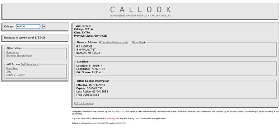 Callook provides a **USA amateur radio callsign lookup service** with data current as of March 25, 2026. The platform allows users to search for valid callsigns and retrieve detailed information, including geographic coordinates sourced from the Bing Maps API. A mathematically calculated **grid square** is derived from these coordinates, though accuracy is not guaranteed due to reliance on external services. The service supports multiple access methods, including a browser search plugin, direct API access with a reference, and plain text output for integration into other applications or scripts. This tool facilitates rapid identification of US amateur radio operators, offering an alternative to other callbook services. Its API access enables developers to integrate callsign lookup functionality into custom applications, streamlining data retrieval for logging software or contest management. The direct presentation of FCC data, combined with grid square calculation, assists DXers and contesters in verifying contact information and location details during on-air operations.
 -
 This page provides a calculator to determine the total line loss and additional line loss in your transmission line based on the level of SWR. It helps hams understand the impact of high SWR on transmission line losses. The calculator allows users to input their SWR level and get accurate calculations of total losses. This tool is useful for ham radio operators looking to optimize their transmission setups and improve overall efficiency.
 -
 This page provides a detailed example of the modeling and analysis of an 80m delta dipole antenna with a 600-ohm bifilar feedline. The model is based on antennas used by the RAF from 1940 to 1970. It covers the original model specifications, conductor mass calculations, resonance frequency observation, geometry adjustment steps, and final antenna dimensions. The content includes theoretical formulas, resonance frequency calculations, and practical steps for adjusting the antenna for optimal performance. Overall, it serves as a practical guide for hams looking to understand and optimize the performance of a delta dipole antenna for the 80m band.
 -
 W4EEY offers specialized preparation materials focused on the mathematics and electronics theory portions of ham exams. Their approach breaks down complex formulas into step-by-step processes, making them accessible even to those without strong math backgrounds. The site includes calculators for common ham radio formulas, interactive circuit diagrams, and in-depth explanations of electronic principles. Their materials are particularly valuable for the Amateur Extra exam, where technical content becomes more challenging.