Search results
Query: 10 meter portable
Links: 42 | Categories: 0
-
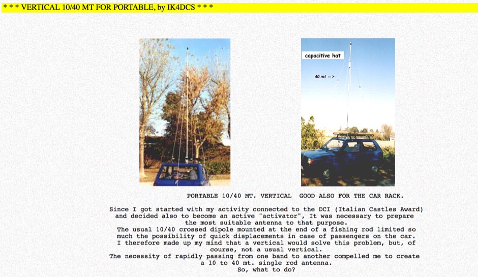 The web page provides detailed information on a portable 10/20/40 meter vertical antenna designed for mobile operations, including modifications for 20 and 40 meters. It includes images and descriptions of the antenna setup in a car. The content is useful for amateur radio operators looking to enhance their mobile communication capabilities.
 -
 This is the antenna w3ff designed for his walking portable station. It is a dipole constructed out of the plastic plumbing pipe CPVC. There are telescoping whips at the ends of each side of the dipole, and these whips are adjusted to bring the antenna into resonance on each of five HF Bands 10, 12, 15, 17, and 20 Meters
 -
 HF Wire Yagi antenna with notes and eznec file on original article of a Portable 3-Band Yagi antenna for 10-15-20 meter band made with wire elements. Include link the original to QST article.
 -
 The Flower Pot Antenna project details a portable dual-band antenna primarily operating on 10 meters, with secondary resonance near the 30-meter band. Construction involves winding RG58 coaxial cable uniformly around a large plastic flower pot, approximately 70cm high with a 60cm top diameter. The design eliminates the need for radials, contributing to its compact and lightweight nature. Key construction steps include soldering the inner conductor to the shield at one end of the wound cable and connecting the wound cable's shield to the rig cable's inner conductor at the base. An LC network, comprising a variable capacitor (0-200pF) and an inductor (10 coils, 5cm diameter, 2mm wire), is inserted between the wound cable's inner conductor and the rig cable's shield. Tuning is performed with an antenna analyzer, adjusting cable length and the variable capacitor for optimal impedance on 10 meters. The antenna performs effectively when installed horizontally.
 -
 A 3 band dipole for 10 15 and 20 meters band, easy to build, and that can be easily setup in any occasion, inclunding field days or portable operations
 -
 This project details three variants of a vertical half-wave antenna design for the 4-meter (70MHz) amateur radio band. The antennas use end-feeding with a parallel-tuned circuit for impedance matching to 50-ohm coaxial cable. The first variant uses suspended flexible wire for portable use, the second employs a fiberglass rod with internal wire for permanent outdoor installation, and the third utilizes aluminum tent poles for quick mobile deployment. Despite the narrow bandwidth of the matching circuit, this suits the narrow 4m FM allocation well. The design offers an effective omnidirectional radiation pattern and can be constructed with readily available materials.
 -
 A Portable 2 element Triband Yagi antenna that can work on 10 15 20 meter band by VE7CA
 -
 A 10-meter J-Pole antenna, detailed in QST February 1950, offers a straightforward solution for hams operating with restricted space. This design, originally presented by W1BLR, is a **half-wave radiator** fed by a quarter-wave matching stub, providing a low-angle radiation pattern beneficial for DX. The article describes building the antenna from readily available materials like copper pipe, emphasizing its simplicity and effectiveness for **single-band operation**. The J-Pole's inherent design provides a good impedance match to 50-ohm coaxial cable without the need for an external tuner, a significant advantage for portable or minimalist stations. Its nondirectional pattern ensures coverage in all directions, making it a versatile choice for general operating on the 28 MHz band. The construction plans are clear, allowing even those with basic workshop skills to assemble a functional antenna.
 -
 End-Fed Half-Wave Antennas (EFHWAs) are analyzed for their utility in portable QRP operations, emphasizing their simplicity, efficiency, and predictable radiation patterns compared to other portable antenna types. The discussion contrasts EFHWAs with vertical antennas, random length wires, and center-fed dipoles, highlighting the common pitfalls of each, such as ground system dependency for verticals and feedline issues for dipoles. The article details the electrical half-wavelength calculation using the formula L (Ft) = 468/F(MHz) and explains how EFHWAs can be resonant on harmonic frequencies, enabling multiband operation. Various deployment configurations are presented, including the inverted L, inverted Vee, sloping wire, and vertical setups, each with specific advantages for radiation angle and polarization. For instance, a vertical EFHWA offers a low angle of radiation suitable for DX contacts without requiring an extensive ground system. The resource also addresses the counterpoise requirements, suggesting a quarter-wavelength wire or connection to a metallic structure for decoupling. A schematic diagram for a simple parallel-tuned circuit tuner, based on the _Rainbow Bridge/Tuner_ design, is provided, detailing component values for 30 and 40 meters, including a 6 microhenry toroidal inductor and a 20-100 picofarad mica compression capacitor. The tuner's adjustment process for SWR matching is also outlined.
 -
-
 The document details the optimization and construction of the _Maria Maluca_ antenna, a compact 6-band (20m-6m) directional beam. It presents a comparative analysis of shortwave antenna principles, highlighting the efficiency gains achieved by using an open feeder line and tuner as a resonant unit, contrasting this with the losses associated with traps or capacitive loads in multiband antennas. The resource specifically revisits an older South American 2-element design for 10, 15, and 20 meters, applying modern NEC-based software to develop a six-band version. Performance data is meticulously tabulated, showing impedance, free space gain, gain at 12m height, elevation angle, and front-to-back (F/B) ratio for each band from 20m through 6m. For instance, on 15m, the antenna achieves 5.1 dBd free space gain and 13.72 dB F/B ratio. The construction section provides practical guidance on element assembly using aluminum pipes and hose clamps, detailing the use of a heavy-duty glass fiber reinforced polyamide rod for electrical separation and bending strength. It also specifies the use of 450-ohm _Wireman_ line CQ 552 for the transmission line. The document includes diagrams for rod fixing, an air-wound balun, and a vertical elevation diagram for the 15m band, illustrating its DX qualification. It also discusses the antenna's suitability for portable and expedition operations, noting its compact transport dimensions (max 1.50m length, 12 lb weight) and quick assembly time (under 15 minutes). The author, Dipl.Ing. Helmut Oeller, DC6NY, is identified as a source for material kits.
 -
 Presents the design and construction of the OK2FJ Bigatas, a portable, automatically tuned vertical antenna covering 80 through 10 meters. It details two distinct control systems: one utilizing BCD band data from Yaesu FT-857/897 transceivers, and another employing voltage level sensing for the Yaesu FT-817. The resource provides specific instructions for building the antenna's radiating element, loading coil with switchable taps, and the control circuitry, emphasizing the use of readily available components. The article outlines the physical construction of the antenna, including the use of duralumin tubes for the radiator and a PVC tube for the coil form. It specifies coil winding details, tap points, and the integration of radial wires for ground plane operation. The control electronics section provides schematics and component lists for both the BCD decoder (using a 74LS42 IC) and the voltage comparator (using an _LM3914_ bargraph driver), enabling rapid, automatic band switching without the minute-long tuning delays common in other systems. Crucially, the antenna achieves rapid band changes, with typical SWR values centered on common operating segments, such as **3.7 MHz** for 80m SSB. It also discusses modifications for CW operation on 80m and the trade-offs between antenna efficiency and full-range automatic tuning on higher HF bands, where manual adjustment of radiator length is suggested for optimal performance on 15m, 12m, and 10m. The resource includes construction photos and a discussion of cable requirements for reliable operation.
 -
 30/17/12 and 20/15/10-Meter Tribanders and a 40 meters inverted V wire yagi antenna
 -
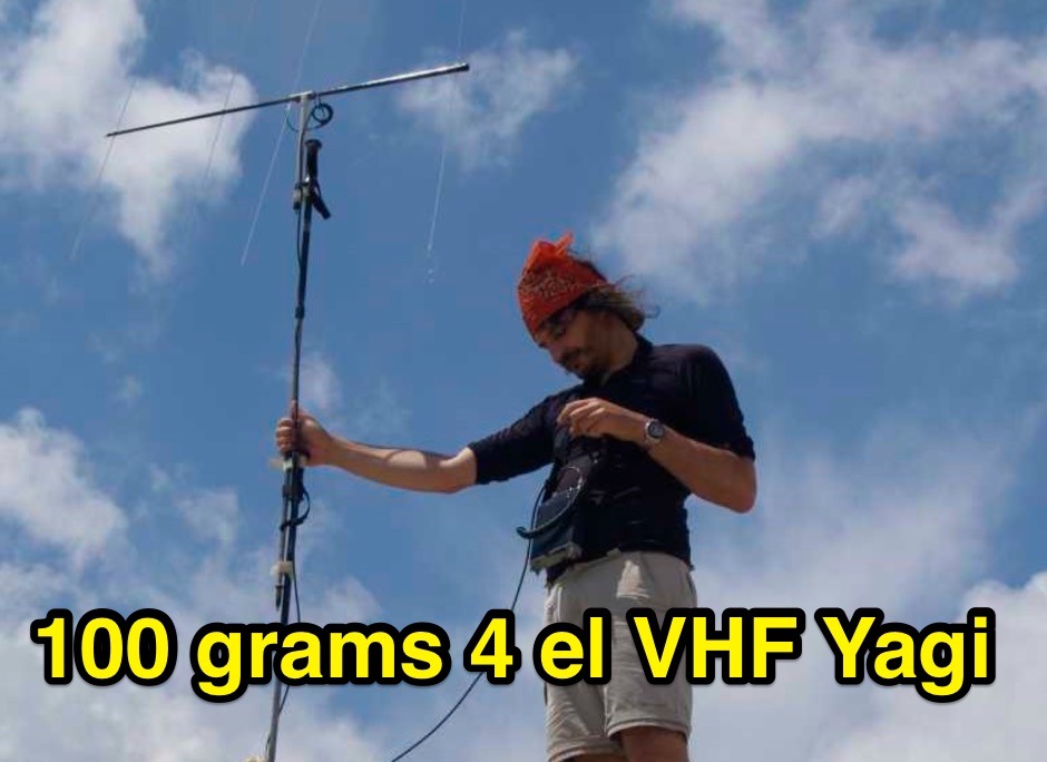 A portable VHF home-made Yagi-Uda antenna, that is extremely easy to build and very cheap. Moreover this antenna, while dismounted is just 1 meter long, and the total weight is just 100 grams.
 -
 A portable 4 elements quad antenna for 144 MHz, 9 to 10 DBd forward gain, 30 DB front-to-back ratio, and 33 DB front-to-side ratio
 -
 Constructing a portable, high-gain antenna for _AO-40_ satellite operations presents unique challenges, particularly regarding mechanical stability and parabolic accuracy. This resource details the build of a 1.2-meter "brolly dish" antenna, utilizing a non-conducting fiberglass umbrella frame as its foundation. The project outlines a method for achieving a parabolic shape using stressed aluminum fly screen mesh, guided by practical geometry and a temporary dowel template. Key steps include selecting an appropriate umbrella with a suitable f/D ratio (ideally >0.25), removing the original fabric, and precisely cutting and attaching eight segments of fly screen to the struts to form the reflective surface. The construction process, which took approximately five hours for the author, _G6LVB_, resulted in a dish with an f/D of 0.27 (depth=270mm, diameter=1160mm, f=310mm). The article also describes a modification to a _TransSystem AIDC_ feed, incorporating a PCB reflector behind the dipole for easier mounting. Performance tests at a squint angle of 15 deg and a range of 50,000km yielded a signal-to-noise ratio of 33dB on the S2 beacon and 23dB for SSB signals, indicating strong reception. The author notes that the modified umbrella may not close fully without risking surface disfigurement.
 -
 Compact and efficient magnetic loop antenna that cover from 40 to 10 meters project by G8ODE published by RSARS
 -
 The X80 multi-band HF vertical antenna, a commercial iteration of the Rybakov design, exhibits a physical length of 5.5 meters, or approximately 18 feet, and is constructed from aluminum tubing. It operates as a non-resonant vertical, requiring an external antenna tuner for impedance matching across its intended operating frequencies. The antenna's design incorporates a 1:4 UNUN at its base, facilitating a nominal 50-ohm feed point impedance for the coaxial cable. Performance observations indicate effective operation on 40 meters, 20 meters, 15 meters, and 10 meters, with reduced efficiency on 80 meters and 160 meters due to its relatively short electrical length for these lower bands. Comparative analysis with a G5RV dipole and a half-wave end-fed antenna reveals the X80 offers a lower take-off angle, beneficial for DX contacts, particularly on the higher HF bands. Field tests conducted with an Icom IC-706MKIIG transceiver and an LDG AT-100ProII autotuner demonstrate the X80's ability to achieve acceptable SWR across 80m through 10m. The antenna's compact footprint and ease of deployment make it suitable for restricted spaces or portable operations, though its performance on 80 meters is noted as a compromise compared to full-size resonant antennas.
 -
 The Superantennas MP-1 portable HF antenna is analyzed for its design and field performance, particularly its high-Q loading coil and 3/8-inch mounting. The review details the antenna's construction, including an 8-inch vertical section, a large-diameter loading coil tuned by a sleeve, and a 4-foot whip that disassembles into six rods for transport. Initial testing with the supplied 10-foot ribbon cable "ground plane" yielded poor SWR and RF hot conditions, indicating an inadequate ground system. Further experimentation with longer radials and resonant counterpoises for each band improved matching and eliminated RF hot issues, but introduced significant operational complexity. The author notes the difficulty in optimizing both counterpoise length and coil setting without an antenna analyzer, and the sensitivity of the MP-1 to counterpoise deployment. The review also discusses the recommendation to tune for maximum received signals rather than minimum SWR, often necessitating an external ATU due to the antenna's typical low impedance. The **MP-1**'s critical dependence on resonant counterpoises for effective operation, especially when elevated, is highlighted as a major drawback for portable use. The author ultimately sold the antenna, concluding that despite its sound technical design, its fussy nature and the need for extensive counterpoise management or an ATU detract from its portability and convenience compared to simpler, less expensive dipole solutions. The **Superantennas MP-1** is deemed a flawed portable antenna, requiring considerable effort to achieve its claimed performance.
 -
 An experimental prototype of an asymmetrical hatted vertical dipole antenna that can work on HF bands 20 to 10 meters band. The AHVD Vertical dipole is an upside-down T design
 -
 A simple portable dipole antenna for the 40 meter band using a total lenght of 18 meter. It can be used for 80 to 10 meters coverage using a antenna tuner.
 -
 The Buddistick antenna, as demonstrated by KP4MD, effectively handles up to **250 watts** and provides coverage from 40 through 10 meters, with an optional coil extending operation to 80 and 60 meters. KP4MD's video presentation meticulously describes the antenna setup, emphasizing the critical role of the _shunting coil_ for achieving resonance on lower bands like 40 and 80 meters. This practical approach highlights how a compact antenna can deliver solid performance from a constrained location. SWR curve diagrams are included, clearly illustrating the impact of the shunting coil on the antenna's resonating frequency. These visual aids provide concrete evidence of the adjustments needed for optimal operation across different bands, particularly when space is at a premium. KP4MD's insights are particularly valuable for hams operating from apartments or other limited spaces, showcasing real-world results from a balcony installation.
 -
 Basically, this antenna is a 23-foot wire fed through a 4:1 un-un transformer. This antenna can be easily used in portable operation, for operating all bands from 40-10 meters.
 -
 The ARRL's End-Fed Half-Wave (EFHW) Antenna Kit is an easy-to-build four-band antenna designed for 10, 15, 20, and 40 meters. Ideal for portable operations, it includes a 49:1 impedance transformer for compatibility with most transceivers. This project, detailed with step-by-step assembly instructions, involves creating a weatherproof enclosure and impedance matching network. The kit simplifies HF operations and supports multiple configurations, making it a versatile tool for amateur radio opertors.
 -
 A 60-foot available space, for example, might necessitate a shortened multiband dipole array to cover 80, 40, and 15 meters effectively. This resource details the construction of such an antenna, combining full-size and coil-loaded dipoles on a single feedline. It addresses the common challenge of fitting multiple HF bands into restricted physical footprints, providing practical guidance for hams with smaller backyards or portable operations. The core of the offering is an interactive calculator that determines required loading coil inductance and dipole lengths for various amateur bands from 160m to 10m. Users input their available space, and the tool provides dimensions, coil turns, and an efficiency rating (Good or Fair) based on the antenna's electrical length relative to a quarter-wavelength. It also suggests suitable _PVC_ pipe diameters for coil forms. The article further illustrates a center feed-point assembly using an 18-inch section of 2-inch _PVC_ pipe, detailing eye-bolt spacing and coaxial connector installation. It emphasizes the importance of adequate spacing between parallel dipoles and offers customization options for the feed-point, including the addition of a _Balun_ for improved feedline isolation.
 -
 This article documents the author's journey in building, modifying, and testing a DIY short vertical antenna for 40, 30, and 20 meters, with potential 80m capability. Initially inspired by Parks On The Air (POTA), the author explores pedestrian mobile operation and details various experiments to enhance antenna performance. The piece highlights challenges, SWR tuning, portability, and practical results, emphasizing a balance between efficiency and size. Ultimately, it showcases the adaptability of DIY antennas for portable ham radio applications.
 -
 Building an End-Fed Half-Wave (EFHW) antenna from a kit, as detailed by Frank Bontenbal, PA2DKW, with process photos by Bob Inderbitzen, NQ1R, offers a practical approach for hams. This specific kit, a collaboration between ARRL and HF Kits, targets 10, 15, 20, and 40 meters, making it a versatile option for HF operations. Unlike a center-fed dipole, the EFHW is a half-wavelength antenna fed at one end, which simplifies deployment, particularly for portable use. The construction guide meticulously outlines the assembly of the 49:1 impedance matching network, crucial for transforming the antenna's high impedance (around 2,500 Ohms) to a transceiver-friendly 50 Ohms. Steps include preparing the enclosure by drilling holes for the coaxial connector and antenna connections, followed by the precise winding of enameled copper wire onto a toroid to create the transformer. The guide emphasizes careful insulation removal and soldering for reliable connections. Final assembly involves integrating a 100 pF capacitor for higher band compensation, soldering the transformer's primary and secondary sides, and conducting SWR tests with a 2K7 resistor or a half-wavelength wire. The document also provides examples of wire lengths for different bands, such as 16 feet for 10 meters or 66 feet for 40 meters, demonstrating the transformer's adaptability for various half-wavelength configurations.
 -
 A portable loop antenna, made with a 3 meter loop resonates with the chosen capacitor from just below 7MHz to about 28.300MHz which makes it usable on the bands from 40m to 10m.
 -
 The antenna I built was inspired by a portable delta loop designed by Doug DeMaw, W1FB. Given that I constrained myself to a 50-foot roll of speak wire, I scaled my antenna for the 20M band. Using the formula, 1005 divided by the frequency in megahertz, I calculated a total length of 71 feet (21.6 meters) for the center of the 20M band.
 -
 Learn how to easily build a 10-meter vertical antenna, perfect for DX contacts on the amateur radio bands. This flowerpot or T2LT design is portable, efficient, and ideal for ham radio operators looking to improve their DX performance. With just a few basic tools and materials, you can construct this antenna for portable operations or as a home station setup. Discover how to set up the antenna, improve its performance by raising it higher, and start making contacts with stations around the world. Watch a step-by-step guide on YouTube for building and testing this DIY ham radio antenna.
 -
 Original HF magnetic loop antenna designed by the author to work in conjunction with QRP transceivers like the FT-817 in portable operations. In this configuration the loop can operate from 30 to 10 meters. Using a two spires radiator of the same diameter it also covers 40 meters.
 -
 Initially planned as an article on the R-407 station mast, this project evolved into creating a custom mast kit. Utilizing original materials, the design was modified for cost-effectiveness and practicality in home assembly. The new mast extends to 10 meters, featuring secure connections, a leather-lined base to prevent metal-on-metal friction, and sturdy military-grade anchors. Modifications include lengthened connecting tubes, improved anti-rotation features, and a convenient base design for solo assembly. Ideal for amateur radio operators, this mast provides stability, ease of construction, and versatility, proving more economical than professional products without compromising on performance or reliability. Article in Czeck.
 -
 Learn how to build your own QRPGuys DS-1 40-10m short vertical antenna for ham radio operators. This page provides detailed instructions on constructing this antenna, which covers the 40 to 10-meter bands. Whether you're a beginner looking to get started with antenna building or an experienced ham radio operator looking for a new project, this resource is useful for anyone interested in DIY antennas for portable or QRP operations.
 -
 The Portable EFHW antenna for the 40, 20, 15, and 10-meter bands utilizes a broadband transformer with a 1:49 ratio, designed on a PCB by either Jan or DL2MAN. The design incorporates an **FT114 core**, offering an alternative to the FT82 core. The antenna requires precisely 20.5 meters of DX Wire Ultralight for optimal performance. Additional components include DX Wires "Dyneema" 1mm rope and 1mm bricklayers string for structural support. The SWR plot indicates performance at two elevation heights: 5.5 meters (blue line) and 4 meters (yellow line), demonstrating optimization for low-elevation portable use without poles. The antenna's components, including spool and rope tensioners, are available for 3D printing, with spool dimensions scaled to 130% for a length of approximately 110mm. The design emphasizes simplicity and portability, suitable for field deployment.
 -
 The 1/4 wavelength vertical antenna project, initially designed for 20 meters, has evolved into a versatile portable solution covering 10 through 60 meters. K0BXB details its construction, emphasizing a bottom-loaded design with a tapped loading coil and four 10-foot counterpoise wires. The author shares personal experiences and field results, including **18 QSOs** during a park activation on 17m and 30m with 10 watts, and a **2,435-mile** contact with a contest station in Bonaire on 20m using 5 watts. Comparisons are drawn to commercial offerings like the _Wolf River Coils TIA_ and _QRPGuys Triband Vertical_, highlighting the DIY antenna's small footprint, light weight, and ease of tuning for POTA activations. The resource includes insights into using test equipment such as the _NanoVNA_ for SWR optimization and discusses various radiator lengths, from 17-foot wire to a 102-inch whip, demonstrating adaptability for different portable setups. Construction tips cover coil winding, tap placement, and connecting feedlines and radials using common components.
 -
 This article presents a novel Top Loaded End-Fed Half-Wave (TLEFHW) antenna design for 20-meter ham radio operation. The antenna features a compact 14-foot vertical radiator with a capacitance hat configuration, eliminating the need for radials or ground systems. Using EZNEC modeling and field testing, the design achieves a 1.5:1 SWR across the 20m band with a 4.11 dBi gain. Key features include quick deployment, lightweight construction, and directional radiation pattern with 110-degree beamwidth. The design, while requiring a 45-foot footprint due to the top hat, offers an effective portable solution for amateur radio operators seeking a no-ground, no-tuner 20m antenna option.
 -
 This tutorial demonstrates how to charge laptops or tablets, like the Microsoft Surface, using off-grid 12-volt batteries typically used for ham radio gear. The guide highlights the importance of selecting a reliable USB-C PD adapter, recommending a 15V, 60W minimum with 5–20V, 3–5A capability. Featured tools include a 100W USB-C adapter and a USB multimeter for monitoring power usage. The video also explores the compact, efficient Power Queen 50Ah LiFePO4 battery for portable power solutions.
 -
 The ICOM IC-705, a popular QRP transceiver for portable operations, often presents unique challenges for field deployment. This resource details practical solutions for common portable setup issues, particularly for _Parks on the Air_ (POTA) activations. It describes a custom bracket for connecting antennas to the IC-705 through a backpack's antenna flap, utilizing a BNC female-to-female chassis mount connector to mitigate cable tangles. The author shares experiences with a DIY magnetic loop antenna, noting its ease of tuning with the IC-705 and successful CW contacts on 40 and 20 meters over distances exceeding **1000 miles**. Another modification presented is a strain relief solution for the microphone cord, replacing the standard spring clip with an easier-to-attach method. The page also mentions using a _Wolf River Parks antenna_ for POTA activations and references the QRPGuys DS-1 antenna as another portable option. Firmware updates and integration with an LDG Z11-Pro II auto-tuner are also discussed.
 -
 A versatile digital VFO design utilizing the Silicon Labs Si5351a oscillator chip and Nokia 5110/3310 graphics LCD display, operating from 1-160MHz with dual VFO capability. This microcontroller-based system, powered by an ATmega328 processor, features rotary encoder tuning, selectable step sizes, RIT control, and comprehensive band memory functions. Drawing less than 40mA at 3.3V, it significantly improves upon previous DDS designs' power consumption while offering advanced features like S-meter display, VFO lock, and programmable BFO/CIO offsets. The design achieves flexible functionality through simple hardware implementation and efficient software architecture, making it particularly suitable for QRP and portable amateur radio applications.
 -
 "The QRP Adventures of VE3FI" is a captivating blog that chronicles the amateur radio experiences of Bill, VE3FI, over two decades. Holding Canadian Basic, 5-word CW, and Advanced licenses, Bill's main interests include DXing and QRP operations. The blog offers detailed accounts of his portable activations, such as a recent outing in March 2025, where he achieved impressive DX contacts on the 10-meter band using just 8 watts and a Hamstick antenna. Bill's engaging storytelling and practical insights make this blog a valuable resource for both seasoned and aspiring amateur radio enthusiasts.
 -
 VE1ZAC's analysis details the performance of **MFJ927** and **SGC239** autotuners with portable HF vertical antennas, specifically comparing 31 ft and 43 ft configurations. The resource originated from challenges encountered during a Maritime QSO Party roving operation, necessitating a lightweight and easily deployable antenna system. Target bands for the contest included 80, 40, 20, 15, and 10 meters, with a maximum power handling of 100 W CW. The author utilized a 30-foot carbon fiber push-up pole to support a vertical wire element, noting its 2 lb weight and reliability. EZNEC modeling was employed to predict performance, showing favorable results for a 30-foot vertical with elevated radials, particularly on 40 and 20 meters. Feedpoint impedance measurements, taken with an AIM4170C, are presented for various HF bands, both with and without a 41-foot RG6 stub designed to reduce reactance on 80 and 20 meters. The stub significantly improved matching on these bands, easing the tuner's workload. Operational tests revealed issues with the MFJ927's reliability during contest setup, leading to reliance on the K3's internal tuner. The SGC239, tested post-contest, performed flawlessly. A detailed side-by-side comparison covers mechanical aspects, connection options, power bias, impedance range, board quality, and documentation. Modifications to the MFJ927, including a new aluminum case, white paint for heat reduction, and upgraded impedance-measuring resistors, are also described.
 -
 The **Yaesu FRG-100** shortwave receiver, introduced in 1992, operates across a frequency range of 50 kHz to 30 MHz, accommodating AM, LSB, USB, and CW modes, with an optional narrow-band FM capability. Its physical dimensions are 238 x 93 x 243 mm, with a weight of 3 kg, making it suitable for both portable and fixed station deployments. Power options include standard mains voltage or 12VDC, providing operational flexibility for diverse listening environments. The front panel integrates a manual tuning knob, an analogue signal strength meter, and an LCD display that provides critical information such as frequency, operating mode, memory channel, and time. Users can configure various operational parameters, including tuning steps and bandwidth filters, to optimize reception for specific signals. This review highlights the FRG-100's straightforward interface and its utility for shortwave listening enthusiasts. The design emphasizes user-friendly adjustments for settings, which contributes to its appeal among those interested in general coverage reception.