Search results
Query: 16 d cell
Links: 14 | Categories: 0
-
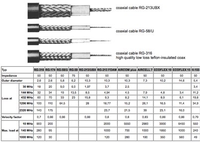 A page with several coax cable characteristics comparison. Includes RG-316 RG-174 RG-58/U RG-59 RG-213/UBX RG-213 FOAM AIRCOM plus AIRCELL 7 ECOFLEX 10 ECOFLEX 15 H-155
 -
 The Yaesu VX-5R, manufactured between 199x and 200x, offers a transmit frequency range covering 50-52 MHz, 144-146 MHz, and 430-440 MHz for European models, with US versions extending to 50-54 MHz, 144-148 MHz, and 430-450 MHz. Its receiver boasts an impressive wideband capability from 0.5 MHz to 999 MHz, with cellular frequencies blocked in some regions. The unit provides up to 5 watts RF output on 6 meters and 2 meters, and 4.5 watts on 70 centimeters, with selectable lower power settings down to 300 mW. This handheld transceiver utilizes a double conversion superheterodyne receiver system, featuring a 47.25 MHz first IF for FM and 45.8 MHz for WFM. Key specifications include a frequency stability of ±5 ppm across a wide temperature range and a current drain of 25-150 mA on receive. The VX-5R supports 220 regular memory channels with alpha tags, 3 home channels, and 10 NOAA weather channels, all stored in non-volatile EEPROM. Additional features include CTCSS/PL and DCS with tone search, ARS, ARTS, an internal voltmeter, and a Spectra-Scope. The device operates on a 7.2 VDC battery pack or 10-16 VDC external power, weighing 255 grams with dimensions of 58x88x27 mm. The VX-5R was also available as the metallic silver VX-5RS.
 -
 The Atmel AVR Butterfly is a credit card sized board which contains an AVR MEGA169 processor, a six character LCD display, a five way joystick navigation switch, a piezo speaker, a 3 volt lithium battery cell for power and a few other odds and ends.
 -
 The Kenwood TS-870S HF transceiver features two state-of-the-art 24-bit 20 MIPS DSP chips, providing over 100dB out-of-passband attenuation and CW bandwidth adjustable to 50 Hz. It operates across 160-10 meters with 100 watts output, incorporating digital filtering, a beat canceller, and 100 memory channels. The radio also includes a transmit equalizer, RX antenna input, and a K1 Logic Keyer, enhancing signal processing and operational flexibility for amateur radio operators. Advanced capabilities include IF stage DSP, dual noise reduction, and an auto notch filter, all contributing to superior signal reception and clarity. The TS-870S offers a variable AGC, voice equalizer, and an RS-232C port for computer control, with Windows™ software supplied. Its built-in automatic antenna tuner functions on all bands for both transmit and receive modes, streamlining station setup and operation. Available accessories such as the DRU-3A digital recording unit, SO-2 high stability crystal oscillator, and VS-2 voice synthesizer option further extend the transceiver's utility. The unit requires 13.8 VDC at 20.5 Amps and is supplied with an MC-43S hand microphone, making it a comprehensive station component.
 -
 An introduction to digital modes DMR Fusion and D-Star. This excellent article will guide you to learn differences between these digital modes by evaluating costs, ease of use and programaming, extendability and more characteristics.
 -
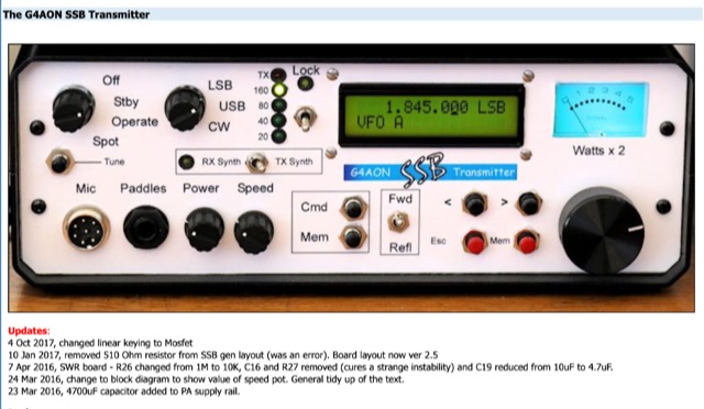 This transmitter covers the 160, 80, 40 and 20 metre bands and provides both SSB and properly generated CW. The CW side of this transmitter is not compromised and produces excellent CW. On SSB the audio has been tailored to provide a rising response to 3 KHz, with a sharp drop above that frequency. There is RF speech clipping to both provide more "punch" and to limit the peak output.
 -
 This practical, hands-on article offers a valuable journey through balun construction for portable antenna systems. The author skillfully navigates from theoretical debates to practical implementation, providing a well-documented DIY process using RG316 micro coax and an FT114-43 toroid core. The step-by-step instructions, complemented by photographs, make this complex technical project accessible to hobbyists. Particularly impressive is the author's focus on lightweight design (just 173 grams) for SOTA field operations. While the final antenna requires minor tuning adjustments, the successful field test during the Pirate Contest demonstrates the effectiveness of this approach. An excellent resource that transforms theory into practical application for ham radio operators.
 -
 This article describes the construction of a simple dual-band VHF/UHF end-fed vertical dipole antenna designed for local repeater access using an Icom IC-705 radio. Built from a single piece of RG58U coaxial cable, the antenna consists of a 460mm exposed inner conductor, 450mm of intact coax, and a 9-turn choke balun wound on a 27mm former. Mounted on a 10m Spiderpole, the antenna achieves excellent SWR readings (<1.2:1 on 2m, <1.5:1 on 70cm) and provides effective coverage of local repeaters with unexpected reach into distant locations.
 -
 Operating from Banana Island, Sierra Leone (AF-037), the 9L2019 DXpedition by F6KOP and a ten-operator team used the callsign 9LY1JM from January 9-21, 2019. This detailed report covers the logistical challenges, including securing visas and licenses with local assistance from Mark 9L1YXJ and Gregory of Dalton’s Guest House. The team deployed monoband quarter-wave verticals on the beach and two Beverage on Ground (BOG) antennas for Europe/Asia and the USA, operating four stations simultaneously. Technical hurdles encountered included high tides submerging antennas, requiring repositioning, and persistent QRM between closely spaced stations, mitigated by doubling filters. CW signal irregularities at 30-32 WPM were resolved by PC and WINTEST restarts. A significant FT8 logging bug was identified and corrected with on-site software. Despite these issues, the team logged over 4,000 QSOs in the first 24 hours, averaging 5,000 QSOs daily, with a peak of over 6,000 in one day. Propagation varied, with excellent 160m conditions on January 12 yielding over 750 QSOs, and a later four-hour opening pushing the 160m total past 1,600. High bands were challenging due to low solar activity, but mid-bands provided intense pileups and rapid continent-wide contacts. The DXpedition concluded with nearly 50,000 QSOs, including a successful school QSO with Collège Doisneau de Sarralbe (57), managed by F1ULQ and F6KFT.
 -
 This study details a reception comparison between vertical and horizontal active loop antennas, specifically two identical _Wellgood active loop antennas_, on various HF bands. The experiment, conducted in a densely populated QRM-prone area, monitored FT8 signals over a 24-hour period using two identical receivers. The methodology involved direct comparison of signal reception across the HF spectrum, aiming to identify performance differences based on antenna orientation. The results indicate that vertical loops demonstrated superior performance on higher bands (10m, 15m, 20m), while horizontal loops excelled on lower bands (30m, 40m, 160m), particularly for receiving long-distance (DX) signals. The horizontal loop's advantage on lower bands is attributed to potentially better low-angle performance and reduced sensitivity to man-made noise, yielding a **2-3 S-unit** improvement on 160m. The study provides practical insights for optimizing antenna placement in challenging urban environments, noting that the horizontal loop consistently showed a **10-15 dB** signal-to-noise ratio improvement on lower bands.
 -
 LZ1AQ describes a versatile QRP antenna tuner that switches between Pi and Tee configurations with a single toggle. Using two variable capacitors and a seven-switch stepped inductor providing 128 increments (0.16 to 18.7 uH), this compact design handles 3.5 to 28 MHz with excellent matching range. The Pi mode works best for certain impedances while Tee mode proves more universal, matching loads the Pi cannot. Built in a plastic enclosure using salvaged radio capacitors, the tuner operates reliably up to 100 watts with proper antennas, though it's optimized for QRP service with random wires.
 -
 This article details the design and construction of a compact 20-meter QRP SSB transceiver by Pete Juliano, N6QW, measuring just 2 x 4 x 2 inches—small enough for a shirt pocket. Inspired by a 1963 QST design and refined from a prior version, it employs bilateral circuits, a 4.9152 MHz homebrew crystal filter, switched-crystal VXO for 60 kHz coverage (14.160-14.220 MHz), and standard components like ADE-1L mixers and IRF510 PA for 1W output. Key innovations include a double-sided PCB skeletal frame for shielding and isolation, Vectorboard sub-assemblies, and ultra-miniature relays. The bilateral receiver/transmitter shares stages, omitting AGC for simplicity, while a W3NQN LPF and optional 10W external amp enable DX contacts. Tune-up focuses on crystal matching and bias for linearity. Videos on YouTube demonstrate performance, confirming excellent stability and audio. Total cost nears $100, prioritizing portability over features like CW.
 -
 The DIY Power Meter project utilizes the _INA226_ high-side power monitoring chip, paired with an ATtiny85 microcontroller, to measure voltage, current, and power, displaying the results on a 128x32 OLED screen. The INA226 communicates via an I2C interface and is programmed with a calibration factor based on the shunt resistance and current register LSB. The project is designed to handle a maximum current of 500mA using a 0.16ohm shunt resistor, which can be adjusted to a 0.2ohm resistor, reducing the full-scale current range to 409mA with a resolution of **12.5uA**. The shunt resistor dissipates only 33mW at maximum current, making 1/4 watt resistors suitable for the setup. The PowerMeter.ino sketch configures the shunt resistance and maximum design current, automatically calculating the calibration factor. The project can be prototyped on a breadboard using an Arduino Uno, employing the Wire library for INA226 and OLED communication, and the u8g2lib library for the OLED display. For the ATtiny85 version, the Adafruit-TinyWireM and Tiny4kOLED libraries are used. The power meter is independently powered by a 3V CR2032 cell, with power switching options including manual switches or DC switched jacks. The low-side n-channel MOSFET switch configuration is tested but introduces voltage drop issues, making manual switching a more reliable option until a suitable DC switched jack is found. DXZone Technical Profile: INA226 | ATtiny85 | OLED Display | Power Meter
 -
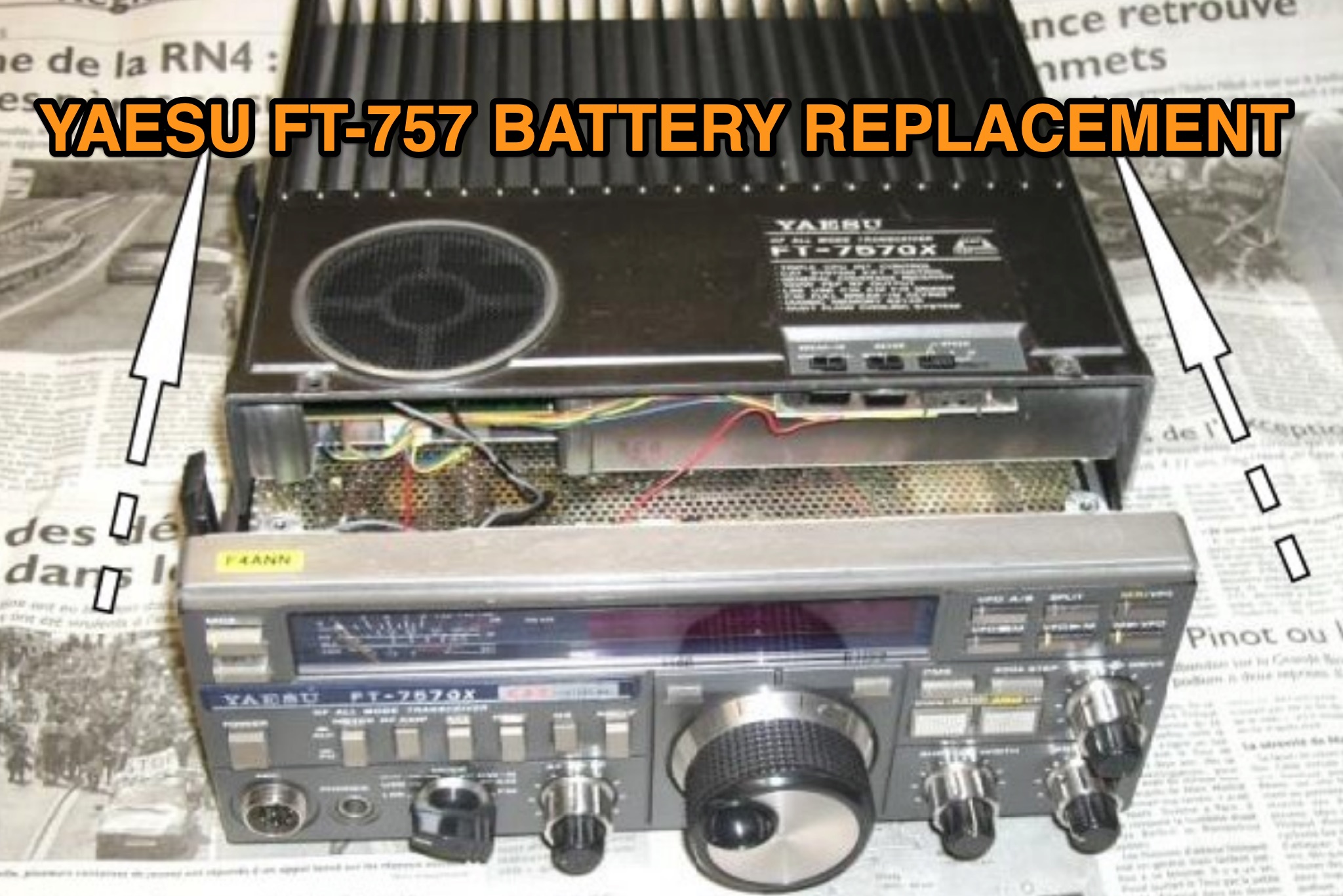 This guide by F4ANN (2014) explains replacing the backup battery in a YAESU FT-757 GX when stored frequencies reset on power-up. The original CR-1/3N lithium cell (3V, 160 mA) can be substituted with a CR2032 (170 mA), which is cheaper, widely available, and easier to replace. The process involves opening the transceiver, carefully desoldering the old battery from the PCB, and wiring in a holder for the CR2032. Extra care is required with screws, connectors, and soldering. The author also replaced backlights and serviced the cooling fan. Future battery replacements are simplified to four screws.