Search results
Query: 4m antenna construction
Links: 16 | Categories: 0
-
 Demonstrates the construction and performance of an updated ZS6BKW multiband dipole, a variant of the _G5RV_ antenna, specifically designed for HF operation. The article details a real-world installation using 13.5m copper wire elements and 12.2m of 450 Ohm ladder line, configured as a sloping inverted-V with the apex at 10m and ends at 4m above ground. It covers the critical aspect of impedance matching, incorporating an 8-turn choke balun at the feedline transition to RG-58U coax to mitigate RF common mode current. Measurements confirm favorable SWR readings below **1.3:1** on 7.1 MHz, 14.11 MHz, 18.06 MHz, and 24.8 MHz, indicating effective resonance across 40m, 20m, 17m, and 12m bands. The installation also shows usable SWR dips on 3.55 MHz (5:1), 29.02 MHz (2:1), and 50.84 MHz (3:1), extending its utility to 80m, 10m, and 6m with an antenna tuning unit. Initial on-air results report clear reception of stations over **5000km** away, validating its DX potential.
 -
 The article "Exploring the World of 10 Meter Beacons" by Ken Reitz, KS4ZR, provides an in-depth look at 10-meter beacon operations, focusing on their utility for propagation analysis. It details FCC Rules part 97.203 governing beacon stations, including license requirements, power limits (under 100 watts), and the specified band segment of 28.200-28.300 MHz for U.S. operations. The content highlights the diversity in beacon construction, from converted CB radios to home-brew QRP transmitters, and discusses the robust operating conditions these 24/7 stations endure. The resource presents several case studies of active 10-meter beacon operators like Ron Anderson KA0PSE/B, Domenic Bianco KC9GNK/B, and Bill Hays WJ5O/B, detailing their equipment, antenna setups, and typical signal report volumes. It also introduces the NCDXF/IARU International Beacon Project, which features 18 synchronized beacons worldwide transmitting on 28.200 MHz at varying power levels (100W, 10W, 1W, 100mW) to facilitate propagation testing. The article also covers the PropNet Project utilizing PSK31 on 28.131 MHz and the 250 Synchronized Propagation Beacon Project on 28.250 MHz. Practical advice for monitoring includes using the RST reporting method, understanding the impact of the solar cycle on 10-meter propagation, and tips for setting up a personal beacon, such as frequency selection and power output considerations. The IY4M Guglielmo Marconi Memorial Beacon Robot on 28.195 MHz is also mentioned for its automatic QSO mode. The article concludes with a list of other resources for 10-meter beacon information.
 -
 The ZS6BKW antenna, a popular multiband wire antenna, offers improved band matching compared to the traditional G5RV. This construction guide details the process, beginning with specific dimensions: 13.11 meters (43 feet) for the 450-ohm ladder line and initial dipole arm lengths of approximately 14.8 meters each. It emphasizes the critical role of an _antenna analyzer_ for accurate tuning, particularly for determining the velocity factor of the ladder line and achieving a 1:1 impedance match. The article outlines the materials required, including a 1:1 current balun, 450-ohm window line, wire for the dipole arms, and a 50-ohm non-inductive resistor for testing. It provides a step-by-step procedure for cutting the ladder line to its electrical half-wavelength, explaining how to calculate the velocity factor using measured and free-space frequencies. For instance, a measured 50-ohm impedance at 12.54 MHz with a calculated free-space half-wavelength frequency of 11.44 MHz yields a velocity factor of 0.91. Final adjustments involve hoisting the antenna to its operational height and fine-tuning the dipole arm lengths to achieve optimal SWR, specifically targeting 14.200 MHz. The _ZS6BKW_ design is noted for its performance on 80m, 40m, 20m, 10m, and 6m, though it is not optimized for 15m operation. The author, _VK4MDX_, shares practical tips for durable construction using stainless steel wire and cable clamps.
 -
 This document details the design and construction of a Vinecom 6N4 dual-band Yagi antenna for the 50MHz (6-meter) and 70MHz (4-meter) amateur radio bands. The antenna features 9 total elements (4 elements for 50MHz, 5 elements for 70MHz) on a 4.236-meter aluminum boom. Computer simulations using MMANA software predict 7.21 dBd gain on both bands with front-to-back ratios of 16.01dB (6m) and 15.37dB (4m). The design uses 12.7mm diameter elements mounted on a 32mm square boom, weighing 5.7kg total. Practical measurements with an MFJ-269 analyzer confirmed good SWR performance across both bands after element length adjustments.
 -
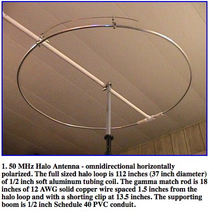 A well documented article about construction and analysis of a horizontally polarized halo antenna for 6 meters band by Dr. Carol F. Milazzo, KP4MD
 -
 Optimizing a G5RV or ZS6BKW multiband wire antenna for HF operation often involves addressing common SWR issues and understanding feedline characteristics. This resource chronicles the construction and performance evaluation of a G5RV, initially built for 80m, 40m, 15m, and 10m bands, by a newly licensed Foundation operator. The author details the selection of materials, including 3.5 mm stainless steel wire for the doublet arms and enameled copper wire for the open-wire feeder, and the initial decision to omit a balun based on common online information. The narrative highlights the initial disappointing performance, characterized by high receive noise and poor signal reports on 80 meters, despite the transceiver's internal ATU achieving a 1:1 match. This led to experimentation with a coax current balun and further research into G5RV myths, such as SWR claims and the necessity of a balun. The author then describes modifying the antenna to the ZS6BKW configuration, which involves specific changes to the doublet and feedline lengths, and integrating a 1:1 current balun wound on a ferrite toroid. The modifications resulted in improved reception and transmit performance across the bands.
 -
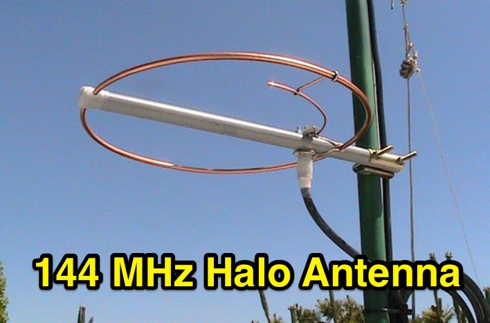 Construction and analysis of a low cost omnidirectional horizontally polarized antenna for 144 MHz, including notes on halo antenna stacking
 -
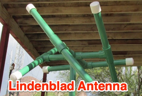 This is a presentation used at OVARC on the LindenBlad antenna construction. The presentation cover several topics about this antenna, from the basic antenna design, to the guide on how to contruct a custom lindenblad antenna for the 2 meters band and and 70 centimenters band.
 -
 This web article details the construction of a 4-meter band coaxial dipole antenna, designed for operation between **70.000 MHz and 70.500 MHz**. The resource provides a bill of materials and step-by-step assembly instructions for a half-wave dipole constructed from _RG-58_ coaxial cable. The design specifies a direct 50 ohm feedpoint impedance, eliminating the need for an external matching network. Construction photographs illustrate the stripping and soldering processes for the coaxial cable elements, ensuring proper electrical connection and physical integrity. The article includes specific dimensions for the radiating elements, derived from calculations for the 70 MHz band. The project outlines the physical dimensions required for resonance at 70 MHz, with the outer braid forming one half and the inner conductor forming the other. The feedline connection is directly to the coaxial dipole's center, maintaining a 50 ohm characteristic impedance. While the article does not present SWR plots or VNA sweeps, it focuses on the mechanical construction and dimensional accuracy for achieving a functional 4-meter dipole. The design is intended for fixed station use, with no specific mention of polarization or height above ground, but implies a standard horizontal orientation for dipole operation. DXZone Focus: Web Article | 4m Coaxial Dipole | Construction Guide | 50 ohm Feed
 -
 A 20-meter window frame stealth antenna, based on a design by _PD7MAA_, utilizes a single 620cm wire loop for discreet installation. The feeding mechanism employs a _4C65_ toroidal core, where the antenna loop functions as a single-turn secondary, and the feedline wraps twice. Tuning is achieved via a 30cm twisted wire stub, allowing for SWR adjustment within the 20m band. This design is specified for QRP operation, with a maximum power limit of **25 Watts** to prevent core saturation or arcing. Wire selection recommendations include thin, insulated copper wire (0.75mm to 1mm) for blending with architectural elements. The guide focuses on practical construction steps for a low-profile 14MHz antenna.
 -
 Building an 80-160 meter antenna in a small garden (9m x 14m) involves creative solutions due to space constraints. This project outlines the construction of a trapped 80-160 meter vertical dipole, utilizing a crank-up tower and an 11-meter fiberglass pole. The design prioritizes minimal visibility, ease of construction, and cost-effectiveness, achieving effective operation despite limited space.
 -
 A coaxial cable trap is a fundamental component in multiband antenna design, enabling a single radiator to resonate efficiently on multiple frequencies by electrically shortening or lengthening the antenna element. This project focuses on constructing such a trap for a vertical antenna operating on the 10 MHz (30m) and 14 MHz (20m) amateur bands, providing practical insights into its fabrication and integration. The article outlines the specific dimensions and winding techniques for the coaxial trap, emphasizing the use of readily available materials. It details the physical construction of the vertical element, including the mast and radiating sections, to achieve optimal performance across both target bands. The author shares personal experiences with similar trap designs, noting their effectiveness in previous horizontal dipole configurations. Key construction steps are illustrated with _original photos_, showing the assembly of the trap and its incorporation into the overall antenna structure. The design aims for a compact footprint, making it suitable for limited space installations while still delivering effective DX capabilities on the **30-meter** and **20-meter** bands.
 -
 144MHz 2m Portable Yagi VHF Beam Antenna. This page contains construction details on a 2 metre 144MHz VHF Yagi beam antenna, designed for portable use.
 -
 This project documents the construction and enhancement of a 30m Vertical Dipole Array (VDA) antenna inspired by Remco 7QNL article. Initial design utilized an 18m Spiderbeam pole and a 4m boom. Improvements included a lighter boom structure using fishing rods and a revised coaxial arrangement for enhanced mechanical stability.
 -
 The resource details the construction of a 433 MHz LoRa APRS iGate and a tracker, both built around _TTGO T-Beam v1.1_ microcontroller boards. Each board integrates an OLED screen, WiFi, GPS, and an SMA antenna connector, powered by an 18650 3.7 V lithium-ion battery or microUSB. The iGate operates on 433.775 MHz, with its status verifiable on aprs.fi, demonstrating practical implementation of LoRa-based APRS solutions. The methodology involves programming the modules using Visual Studio Code with the PlatformIO plugin. This process loads the necessary firmware and a JSON configuration file, which includes the operator's callsign and WiFi credentials for the iGate. The guide emphasizes the ease of programming and provides specific steps for configuration. Initial testing of the iGate and tracker, including smart beaconing configuration, is documented. The low power output of approximately 200 mW from the LoRa board's transmitter is noted, with suggestions for range extension through improved antennas or RF amplification. The author, N4MI, plans to deploy a higher-gain 70cm antenna for the iGate.
 -
 The 4m Slim Jim antenna project provides a construction guide for a low-cost, high-performance aerial designed specifically for the 70 MHz FM band. This design achieves a 1:1 SWR across the 4m FM band with straightforward adjustment of the feed point, utilizing RG-58 coax. Its low angle of radiation contributes to effective signal propagation. Construction involves using plastic knitting needles as spreaders and a telescopic fishing pole for support, with components secured using two-part epoxy. Annealed bare single-core copper wire forms the radiating element. The setup process includes raising the antenna at least 3 meters above ground for tuning, adjusting the RG-58 feed point for optimal SWR, and then soldering connections. Waterproofing is achieved with yacht varnish. The design emphasizes low wind resistance for durability, making it suitable for exposed outdoor installations. A PDF construction diagram is available to supplement the written instructions.