Search results
Query: 50 ohm dummy load
Links: 12 | Categories: 0
-
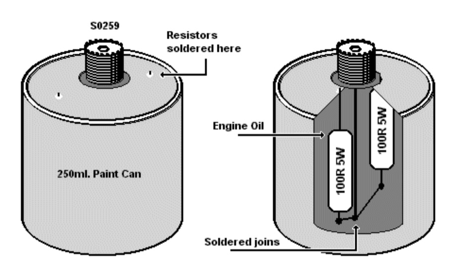 Make your own dummy load with two 100-ohm 5W resistors
 -
 This article describes a low-cost, low-to-moderate power dummy load, which presents a 50-Ohm resistive load from HF through 440MHz.
 -
 This homebrewed antenna tuning unit also incorporates a 50-ohm QRP dummy load, power meter (1 or 10 Watts full scale), and SWR meter
 -
 This project shows how to build a 50-ohm dummy load using non-inductive resistors, oil for heat dissipation, and a simple assembly process. It enables accurate transmitter tuning, testing, and power measurement across LF to UHF bands. The setup allows meter calibration by measuring peak voltage, applying diode drop correction, and calculating RMS voltage and power precisely. Parts are inexpensive and widely available. With proper assembly, this dummy load offers extended service life, accurate readings within 2%, and a reliable alternative to costly commercial wattmeters for amateur radio applications.
 -
 Details a practical QRP wattmeter construction, leveraging a simplified SWR meter design by JA6HIC. The project focuses on a forward-only power measurement circuit, providing a functional instrument for RF power levels from milliwatts up to 5 watts. It maintains a 50-ohm input and output impedance, suitable for typical QRP transceivers and antenna systems. The resource includes the schematic for the "VSW" (Very Simple Wattmeter) and outlines a six-step alignment procedure. This calibration process involves using a known RF source up to 5W, setting full-scale deflection, and marking power increments. It also addresses minimizing frequency effects on readings with a 100pF trimmer capacitor, noting that measurement error is highest at the lower end of the scale. Construction notes mention using a piece of RG-213 coaxial cable for the inductance and coupler, with the wattmeter assembled in early 2003. The author provides an example measurement showing 0.8W into a dummy load and 1W into a 3-element beam.
 -
 This simple 30m QRSS beacon is built entirely out of junkbox parts, the only component purchased specifically for this project was the 10,140kHz crystal. Hans Summers' 30m QRSS beacon project emphasizes simplicity and low cost, built almost entirely from reused parts. Key components include a 10,140kHz crystal, a 2N3904 transistor from a broken DVD player, and an ordinary LED used for frequency shift. The oscillator is stabilized in a polystyrene box, with power amplification driven by recycled copper PCB. Output power peaks at 360mW, and a custom 50-ohm dummy load manages heat. Though aesthetically unconventional, the beacon works effectively, fulfilling the project's low cost aim.
 -
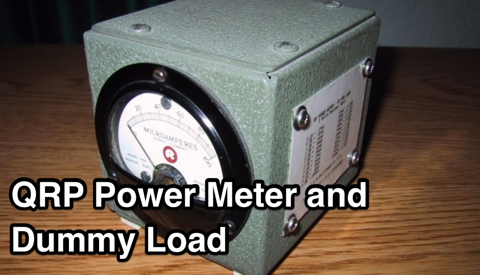 In this article the schematic is of AA5TB QRP power meter and dummy (50 Ohm) load combination
 -
 A homebrew dummy load is usually a combination of several parallel carbon resistors, in order to be able a final resistance of 50 Ohms.
 -
 If your doing any home brewing gear for ham radio its a great idea to have a dummy load. This will to your radio be the perfect antenna...it will never radiate but your radio sees a perfect 50 Ohm impedance.
 -
 A simple 50 ohm dummy load to test transmitters. includes a simple RF diode detector to measure the peak voltage, and calculate the power
 -
 An homemade 50 Ohm 140 W dummy load based on an idea and project by ON5DB Renaud.
 -
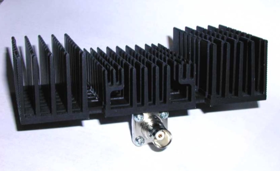
 Twenty 1-watt carbon film resistors are configured in parallel to construct a 50-ohm **dummy load** for amateur radio applications. The design incorporates a heatsink for thermal dissipation and an **SO-239 connector** for RF input, making it suitable for QRP operations. This budget-friendly project details component selection, soldering techniques, and mounting procedures, achieving a continuous power rating of 10 watts and intermittent handling of up to 100 watts across HF and VHF frequency ranges. The resource provides a step-by-step guide for assembly. This construction offers an economical solution for essential shack tasks such as antenna tuning, transmitter testing, and SWR meter calibration without radiating an RF signal. The utilization of readily available components significantly reduces the overall build cost compared to commercial alternatives, providing radio amateurs with a functional and reliable test accessory. While specific VSWR measurements are not provided, the design prioritizes practical utility for low-power transceiver diagnostics and general RF experimentation.