Search results
Query: 600 watt
Links: 15 | Categories: 0
-
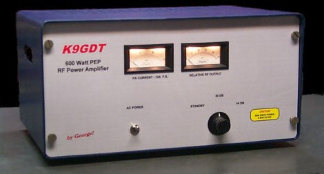 Schematics plans by K9GDT and all infos to build a 600 Watt HF Amplifier. The amplifier uses four Motorola MRF150 50 volt TMOS power FETs configured in push-pull/parallel and biased for class AB linear operation.
 -
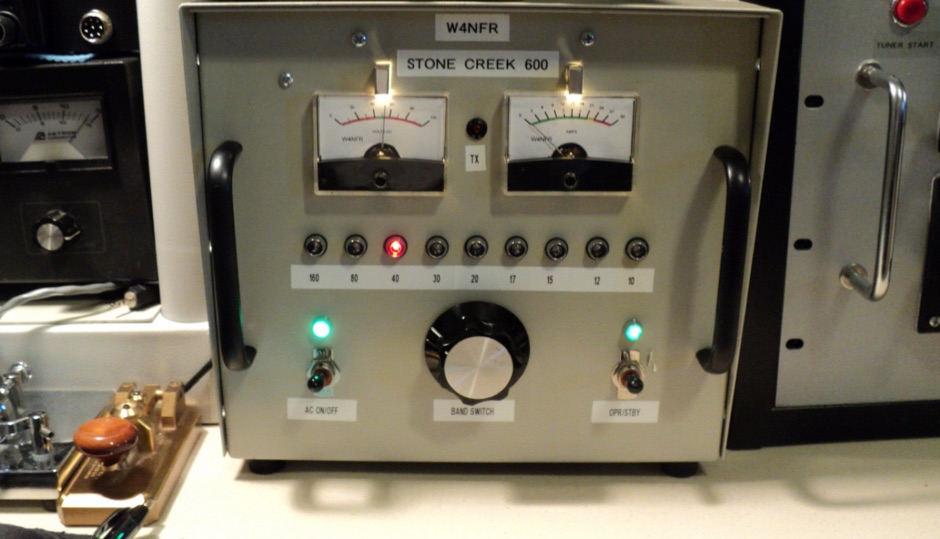
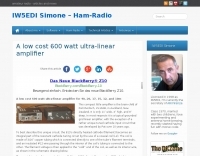 This compact little amplifier is the brain-child of Pat Murdoch, ZL1AXB, in Auckland, New Zealand. It is only 11" wide, 4" high, and 9" deep. Operates for 40, 20, 17, 15, 12, and 10m
 -
 Constructing a high-power solid-state amplifier for HF operations presents unique challenges, particularly when aiming for significant output like 600 watts. This project details an amplifier design employing **Motorola MRF150** FETs, a common choice for their robust performance in RF power applications. The design emphasizes achieving substantial power output, a critical factor for effective DXing and contesting, where every decibel can make a difference in signal propagation and readability. While specific circuit diagrams or construction details are not directly presented on the current page, the mention of MRF150 FETs points towards a design that would typically involve push-pull configurations, impedance matching networks, and robust power supply considerations to handle the high current demands. Such amplifiers are often built with an eye towards linearity and efficiency across the HF bands. Amateurs pursuing similar high-power solid-state projects often share insights on thermal management, intermodulation distortion, and component sourcing, all vital for a stable and reliable amplifier capable of delivering 600 watts into a proper antenna system.
 -
 G3WZT John Matthews project of a 600 Watt solid state linear amplifier for the 6 meters band
 -
 A solid state linear based on EB104 Motorola Engineering Bulletin by Helge Granberg. It uses 4 MRF150 FETs in push-pull parallel to acheive 600 Watts from about 6 Watts drive
 -
 The **United States Islands (USI) Awards Program** is an amateur radio operating activity centered on activating and chasing islands located within the fifty states of the United States, its territories, and protectorates. These islands encompass coastal shores, lakes, rivers, ponds, and streams, offering a diverse range of operating environments. The program provides numerous achievement awards for both island activators and island chasers, encouraging portable operations and mini-DXpeditions. Participants engage in year-round activities, including the **One-Day-Getaway (1DG)**, a casual portable operation held on the second Saturday of May, and the U.S. Islands QSO Party (IQP), a 15-hour contest occurring on the last full weekend of August. USI encourages hams to discover and operate from islands in their local areas, providing an alternative to traditional Field Day operations for outdoor radio enjoyment. The program supports various operating styles, including portable, walk-on, paddle-to, motor-to, mobile, and drive-on activations. Recent activities include AC1RH activating MA064R Eagle Island daily, aiming for over 100 activations using 600 watts, and KD9ZAB and KD5YZY qualifying MO021R Tower Rock, which is also a POTA US-10147 location. The USI program maintains a clear distinction from the Islands On The Air (IOTA) awards program.
 -
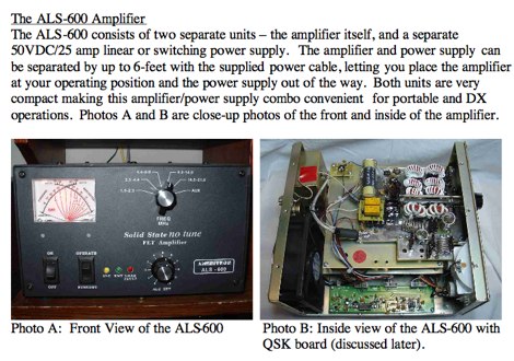 The Ameritron ALS-600 600-Watt HF Power Amplifier review by AD5X
 -
 AL-811 and AL-811H specifications and information about this 600-800 Watt ham radio ower amplifiers
 -
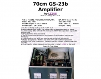 1500 watts of RF output on the 70cm band requires robust amplifier design, a challenge addressed by this project featuring the GS-23b / 4CX1600U Svetlana tube. The resource details the construction of a high-power UHF amplifier, providing insights into component selection and layout necessary for stable operation at these frequencies and power levels.
 -
 Constructing a high-power 70cm solid-state amplifier presents unique challenges, particularly when aiming for 500 watts output using modern LDMOS devices. This resource details the author's experience building a 70cm amplifier based on a _Freescale MRFE6VP5600H_ transistor, initially from an RFHAM kit. It meticulously outlines the necessary modifications to achieve advertised performance, including optimizing input and output matching, correcting bias circuitry, and ensuring proper output balun connections for stability. The author shares specific adjustments, such as trimming the prototyping board for better transistor fit, drilling additional mounting holes for improved heat sinking, and replacing original matching capacitors with a single _20pf MIN02 metal mica_ for superior output. A critical fix involved jumpering gate decoupling pads to balance the push-pull transistor halves, which increased output to 580W and improved IMD. The resource also highlights a crucial correction to the output balun connection, initially reversed in the _Dubus_ article schematic, which resolved intermittent stability issues. Test results are provided, showing input power, output power, and drain current at 50V, demonstrating the amplifier's performance after modifications. This practical account offers valuable insights for hams undertaking similar high-power UHF amplifier projects, especially those working with LDMOS devices and kit-based constructions.
 -
 On March 27, 2017, the FCC adopted final rules for the USA 630-meter band, detailed in Report and Order FCC 17-33, which required PLC coordination with the Utilities Telecom Council before amateur operations could commence. This resource documents the WD2XSH experimental group's activities, including authorized stations, band plans, and frequency assignments within the 465-515 KHz range, with many stations operating between 495-499 KHz and 501-510 KHz. The site also highlights the WRC-12 decision on February 14, 2012, which granted a new **7-kilohertz-wide** secondary allocation between _472-479 kHz_ for the Amateur Radio Service worldwide. The group's efforts included operating with a maximum ERP of **20 Watts** across 45 stations in the continental USA, Alaska, and Hawaii, using emission modes such as CW, PSK-31, FSK-31, and MSK-31. The site provides links to download FCC 17-33 in PDF and DOCx formats, and offers a station location map, a list of stations by callsign and frequency, and an archive of news updates. Reception reports for any 600-meter station are encouraged to help the amateur radio community understand propagation and repeatability on this challenging band.
 -
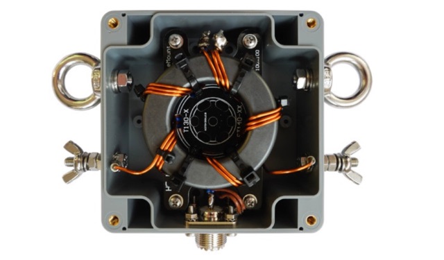 This Guide helps you to build the 1:2 BalUn 600 Watts DIY kit step by step. If a delta-loop or quad-loop antenna is powered with a coax cable from the transceiver it is necessary to use a 1:2 BalUn. This 1:2 BalUn uses a symmetrical 1:2 impedance transformer.
 -
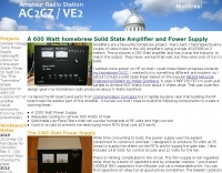
 This is a Solid State Amplifier Project. It uses 4 MRF150 MosFet Power Transistors. The Power Supply Voltage is 50 VDC at 21.5 Amp. The max power available is 1,075 Watts. The Efficiency is about 65% +/- and runs Class AB Solid State.
 -
 A C-Pole Antenna for QRPxpeditions describes a DIY C-Pole antenna designed for QRP (low-power) expeditions, inspired by KF2YN’s ground-independent vertical model. After adjustments, it achieved a 1:1 SWR at 14.060 MHz, rising to 2.5:1 at 14.35 MHz. A choke balun, comprising 15 turns of RG8X around a 4†can, was essential for optimal performance. Compact and self-supporting, the antenna enables reliable communication with minimal setup. Contacts included stations across the U.S., and even a 4,600-mile connection to Spain using only 5 watts.
 -
 An Arduino-based interface provides a remote tuner call command for Icom **IC7700** and **IC7800** transceivers, addressing the lack of a built-in function for external tuners such as the MFJ 998RT. This setup initiates a low-power transmit signal, typically 15 watts, allowing the remote autotuner to perform its matching sequence. The article details the required CI-V line communication and modifications to existing Arduino code, specifically referencing contributions from Jean-Jacques ON7EQ for improved Icom interrogation routines. The system involves a sequence of steps: storing the transceiver's current mode and power, disabling the internal autotuner, activating a control relay to interrupt the amplifier line, switching to RTTY mode at low power, and initiating transmit. The transmit duration is manually controlled by the operator, observing the SWR meter until a low SWR is achieved, then a second button press stops the transmission. A built-in 4-second transmit limit provides a safety measure. After tuning, the routine restores the original mode and power settings, re-enables the internal autotuner, and performs a brief 2-second RTTY transmission for internal tuner adjustment. The circuit diagram includes a Panasonic form 2 relay for amp control and emphasizes critical delays in the Arduino code for stable operation at 9600 baud CI-V communication. Compatibility with logging software like DXLab, N1MM, and N3FJP is noted, with specific interrogation time settings required to avoid conflicts.