Search results
Query: 706 power up
Links: 6 | Categories: 0
-
 This resource provides a historical listing of **unlicensed amateur radio beacons** active in the United States as of December 1993, specifically detailing both **LOWFER** (Low Frequency Experimental Radio) and **MEDFER** (Medium Frequency Experimental Radio) operations. The data includes beacon frequencies in kilocycles (Kc), identification codes, state locations, and the callsigns or names of the beacon operators. Frequencies range from 166.667 Kc for LOWFER to 1706.0 Kc for MEDFER, illustrating the spectrum utilized by these experimental stations. The information was originally compiled by Mark Burkart and relayed to the rec.radio.shortwave newsgroup by Rick Robinson, KF4AR. The list serves as a snapshot of experimental beacon activity from the early 1990s, offering insight into the types of operations and the individuals involved in unlicensed, low-power transmissions. It highlights specific beacon IDs like "ABC SC" on 510.5 Kc and "GK HI" on 1620 Kc, alongside operator details such as Todd Roberts (WD4NGG) and Herb Vanderbeek (WY6G). While not a current operational guide, it is a valuable historical document for those interested in the evolution of LF/MF experimental radio and the early days of internet-based amateur radio information sharing.
 -
 If your IC-706MKIIG will not power up without even hearing a relay click, check the state of the HV line.
 -
 Illustrates the specific wiring and configuration steps required to interface an SGC-230 Smartuner with an Icom IC-706 HF/VHF/UHF transceiver. The document details the necessary connections for power, control, and RF signal paths between the two devices, ensuring proper impedance matching and automatic antenna tuning functionality. It specifies the pin assignments for the IC-706's ACC socket and the SGC-230's control port, crucial for successful integration. Outlines the operational considerations for the combined system, including initial setup procedures and potential troubleshooting tips for common connectivity issues. The resource presents a clear, diagrammatic representation of the interconnections, which aids in visual comprehension of the required cable fabrication or modification. Covers the specific settings within the IC-706 menu that need adjustment to enable external tuner control, such as the 'TUNER' function and other relevant parameters. This ensures the transceiver correctly communicates with the SGC-230 for efficient antenna tuning across various amateur bands.
 -
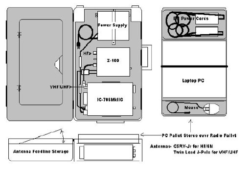 A Portable 100 watt radio station setup composed by a 706MKII transceiver, Z-100 antenna tuner and power supply by N1GY
 -
 DF0WD/DL4YHF's Longwave Overview details amateur radio operations on the 135.7 to 137.8 kHz segment in Germany. The author outlines the "inofficial" European band plan, specifying segments for QRSS, TX tests, beacons, conventional CW, and data modes. Early LF activities at DF0WD began with a 20-watt CW transmitter, later upgraded to a homemade linear transverter capable of 100 watts, driven by an Icom IC706 on 10.137 MHz. The station's antenna system includes a 200-meter wire, approximately 10 meters above ground, supported by football field light-masts. Despite its length, the antenna's efficiency is noted as very low due to the immense wavelength of about 2.2 km. The author's experience highlights the significant challenge of achieving effective radiated power (EIRP) on LF, estimating DF0WD's EIRP at around 80 milliwatts based on field strength measurements from PA0SE. DF0WD/DL4YHF has successfully worked numerous countries on 136 kHz CW, including DL, F, G, GI, GM, GU, GW, HB9, HB0, LX, OE, OH, OK, OM, ON, OZ, PA, and SM. The author also mentions ongoing efforts to log contacts with CT, EI, LA/LG, and to complete a two-way QSO with Italy, demonstrating persistent activity on this challenging band.
 -
 After years of reliable performance, a 26-year-old Icom 706MK2G exhibited an unusual deviation during FM transmission, with the actual frequency being 10kHz off from the displayed frequency. Additionally, the power meter showed a sharp dip during transmission. Upon investigation, it was discovered that the FM VCO voltage adjust variable had become dirty and sluggish over time. By adjusting the variable capacitor and cleaning it with switch cleaner, the issue was resolved, restoring stable power output and accurate frequency transmission.