Search results
Query: arte
Links: 209 | Categories: 1
Categories
-
 2-Element parasitic Yagis for the Shortwave-Bands 10-12-15-17-20-30m. The antennas are feeded with the DK7ZB-match. A quarter-wave choke of coax is grounded at the socket.
 -
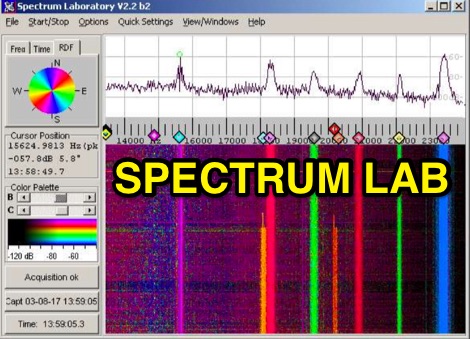 Audio Spectrum Analyser Spectrum Lab or Speclab started as a simple FFT program running under DOS a long time ago, but it is now a specialized audio analyzer, filter, frequency converter, hum filter, data logger and more. Can be used for MTHELL QRSS, DFCW, PSK, MSK, Castle. Spectrum Lab is a free audio analysis tool, lets you see the hidden world of sound. It analyzes live audio or recordings, showing you the exact frequencies present. Watch sounds change over time with a waterfall display. Need to clean up your audio? It can filter out noise in real-time. Even play with radio signals by decoding and creating special modes! While ideal for amateur radio enthusiasts, anyone can explore the science of sound for free.
 -
 This PDF article from April 2001 QST details the construction of the "NJQRP Squirt," a reduced-size 80-meter inverted-V dipole antenna. The resource provides a general construction sketch, a photograph of the assembled antenna, and specific dimensions for PC-board insulators. The antenna consists of two wire legs, each approximately **34 feet long**, separated by 90 degrees, fed at the center. It is designed for operation on 80 meters (3.5-4.0 MHz) as a quarter-wavelength antenna, requiring a low-loss feedline and an external antenna tuner due to its non-resonant feedpoint impedance. Construction utilizes readily available materials, including 1/16-inch glass-epoxy PC board for end and center insulators, and #20 or #22 insulated hookup wire for the elements. The feedline specified is 300-ohm TV flat ribbon line, with a note on potential trimming for tuner compatibility. N2CX reports the antenna's center should be elevated to at least **20 feet**, with ends no lower than seven feet above ground, resulting in a ground footprint of approximately 50 feet wide. The design prioritizes NVIS propagation for local 80-meter contacts. DXZone Focus: PDF Article | 80m Inverted-V Dipole | Construction Notes | 34 ft element length
 -
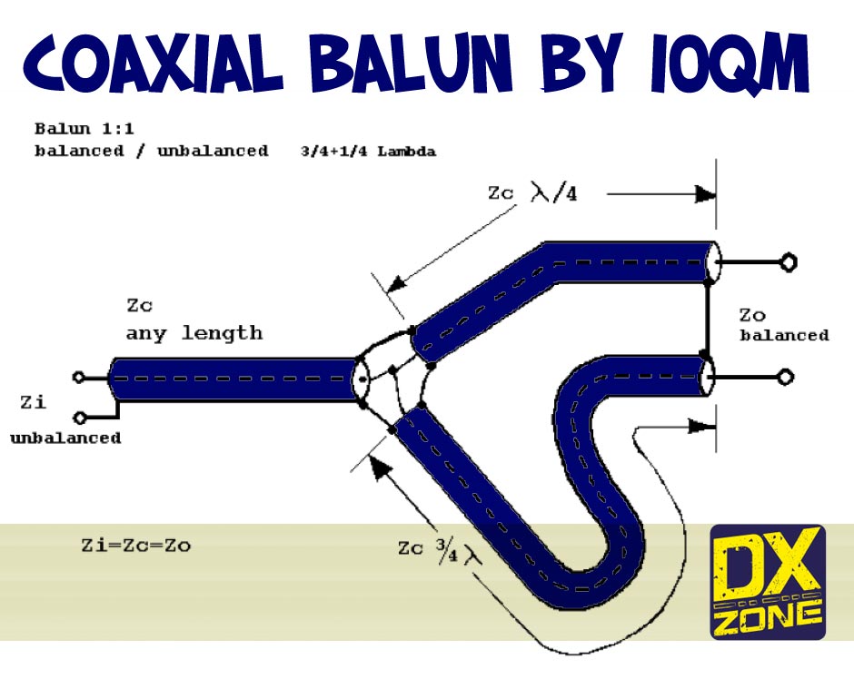 PDF article about a coaxial 1:1 balun, original concept by I4BBE using a quarter-wavelength and the three-quarter-wave adapting sections with the 50-Ohm coaxial cable by I0QM
 -
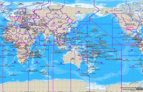 The website provides a free to download large Jpeg DXCC map with amateur radio prefixes and CQ zones. It is a valuable resource for radio amateurs looking to identify DX entities and zones for their operations.
 -
 Details the construction of a J-vertical antenna specifically for the 10-meter band, offering a practical alternative to a _Slim Jim_ design for 28 MHz. The resource outlines the use of aluminum tubing for the half-wave vertical section and coaxial cable for the quarter-wave matching section, providing specific calculations for element lengths based on frequency and coaxial cable velocity factor. It contrasts the performance of the J-vertical with center-fed dipoles and end-fed verticals, noting superior results in previous comparisons. The article further presents a more recent iteration of the J-vertical, constructed using a fiberglass pole and insulated wire, with updated dimensions for 28.8 MHz. It includes practical advice on weatherproofing connections and securing the antenna for durability against adverse conditions, referencing the survival of an original _J Vertical_ during 110 MPH winds in 1987. The SWR performance is reported as 1.1:1 at 28.6 MHz, maintaining below 1.5:1 across 28.3 to 29 MHz.
 -
 4 Element Cubical Quad, Yagis, LZA Circular Quad, Shrunken Quad , quarter wave, J-Pole, beam mounting , changing polarity
 -
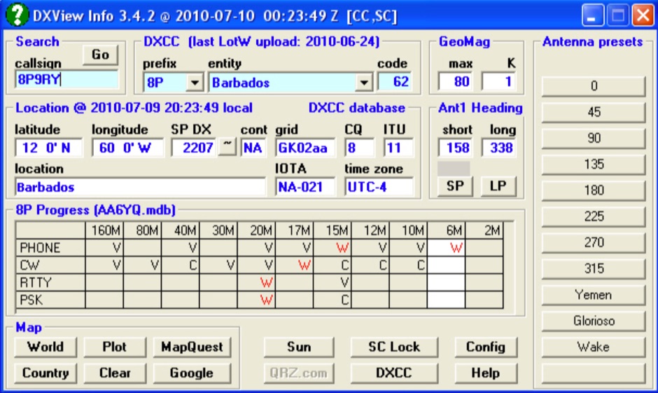 A free application that displays location information determined from a callsign, displays translations of common "QSO words and phrases" in the languages used in the callsign's DXCC entity, displays beam headings and SpotCollector DX Spots on a world map, displays country maps, and provides point-and-click control of antenna rotators from AlfaSpid, ARSWIN, Heath, Hygain, M2, Prosistel, SARTek, TIC, Trackbox, and Yaesu
 -
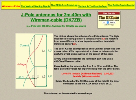 J-Poles with Wireman-cables for the quarterwave matching section, working on VHF and HF bands
 -
 The antenna was named for W4JRW who invented it and holds a patent on the basic principle and uses quarter wave stubs, 80, 40, 20, 15 and 10 meter bands
 -
 Details the construction and optimization of antenna systems for amateur radio satellite operations, focusing on practical, homebrew solutions for VHF/UHF bands. It covers building _groundplane antennas_ from salvaged materials, recycling old beam antennas into new configurations like a 2-meter crossed yagi, and constructing a 10-meter horizontal delta loop. The resource also explains antenna matching techniques, including folded dipole driven elements and quarter-wave transformers, along with the importance of accurate SWR measurements and minimizing coax loss. Demonstrates how to achieve a **1:1 SWR** by carefully trimming elements and adjusting radial angles on groundplane antennas. It provides insights into selecting appropriate coax and connectors, highlighting the benefits of Belden 9913 for low loss and the proper installation of _N-connectors_. The article also addresses RFI mitigation from computer birdies and presents a design for a silent triac antenna control circuit, offering practical solutions for common satellite station challenges.
 -
 The best antenna is the simple Dipole. If you have height, you even can put up a quarter wave vertical or an inverted, but sometimes you may need shorten version by 4S7NR
 -
 PKW Antennas for ham radio bands, Quads, delta loops, log periodics antennas for military and professional use by Ditta Martelli fabbrica italiana antenne
 -
 Alinco's factory in Toyama, Japan, holds ISO9002/140001 certification, underscoring its commitment to quality manufacturing processes for amateur radio equipment. The company produces a diverse range of products, including HF transceivers, mobile VHF/UHF radios, handhelds, and scanners, serving both new and experienced operators within the ham radio community. Their product line extends beyond transceivers to encompass essential accessories such as antenna tuners and power supplies, which are crucial for complete station setups. These offerings support various operating environments, from portable field operations to fixed home stations, ensuring versatility for radio amateurs. Alinco, Inc. Electronics Division is headquartered at Yodoyabashi Dai-Bldg 13F, 4-4-9 Koraibashi, Chuo-ku, Osaka 541-0043 Japan, maintaining a global presence in the amateur radio market.
 -
 The PSK31 philosophy, tips and tricks, sound files, how to get started, sound card setup and tips.
 -
 Examines the current geopolitical landscape of Armenia, offering detailed reports on regional developments and internal political discourse. The station, _Radio Azatutyun_, covers critical discussions such as the potential for conflict in September, with one source suggesting a "war is coming, it won't be delayed," alongside ongoing debates about Armenia-EU visa liberalization, which is projected to require "another 2-3 years" for completion. It also highlights the contentious rhetoric surrounding the Prime Minister's interactions with displaced persons from Artsakh. The resource delves into significant international relations, including discussions between Bayramov and Araghchi on regional situations, and Iran's denial of recent negotiations with the US. It also features updates on former President Trump's demands for an additional **$200 billion** for defense and his assertion that "regime change" in Iran is effectively underway. Further content includes analyses of drone attacks in Baku, the proposed new Constitution, and local issues such as the delayed reconstruction of Gyumri's central market and the persistent problem of Vanadzor's temporary kindergartens. The platform also hosts podcasts like "The Choice is Yours," exploring the reliability of pre-election polls.
 -
 The 30/40 meter **vertical antenna** project by IK4DCS details the construction of a shortened, self-supporting design, reaching a total length of 5 meters. The antenna incorporates a linear loading section and a coaxial cable trap for 30 meters, based on the "Antenne Volume 2°" text by Nerio Neri (page 223). The design uses six radials, three for each band, positioned at approximately 90° inclination and at least one meter above the roof or ground, connected via a 1:1 balun at the feed point. Mechanical construction utilizes aluminum tubing, with a 2.30-meter primary radiator section (30 mm diameter) joined to a second part using a Teflon insert and a PVC sleeve for rigidity. The linear load, approximately 3.70 meters long, accounts for a 30% physical shortening of the quarter-wave element. A capacitive load, made from three 50 cm radials, is integrated into the 40-meter top section for fine-tuning. Final adjustments involved radial inclination for 40 meters, as initial testing showed increased SWR and interference on 30 meters due to nearby resonant structures. The author emphasizes the importance of clear space for optimal performance and provides drawings and photos to clarify the build process.
 -
 This project started as a result of renewed interest in 40 meters coupled with the desire for an antenna system that would be more effective than the simple dipole.
 -
 A 10-meter J-Pole antenna, detailed in QST February 1950, offers a straightforward solution for hams operating with restricted space. This design, originally presented by W1BLR, is a **half-wave radiator** fed by a quarter-wave matching stub, providing a low-angle radiation pattern beneficial for DX. The article describes building the antenna from readily available materials like copper pipe, emphasizing its simplicity and effectiveness for **single-band operation**. The J-Pole's inherent design provides a good impedance match to 50-ohm coaxial cable without the need for an external tuner, a significant advantage for portable or minimalist stations. Its nondirectional pattern ensures coverage in all directions, making it a versatile choice for general operating on the 28 MHz band. The construction plans are clear, allowing even those with basic workshop skills to assemble a functional antenna.
 -
 All copper J-Pole antennas for sale. 6 meter, 2 meter, 222 MHz, 440 MHz, LPFM, Marine, GMRS. Includes a construction plan in pdf format if you wish to build your own antenna.
 -
 A Site to help you get started in QRP, including building your own QRP radio.
 -
 A 20 meter quarter wave vertical antenna by jerry sevick W2FMI QST Article
 -
 Constructing a **2-meter** J-pole antenna from readily available copper plumbing components offers a robust and cost-effective solution for VHF operation. This design, dubbed the "Plumber's Delight," functions essentially as a half-wave dipole fed by 50-ohm coax via a **gamma match**. It incorporates a quarter-wave copper tubing support, which, when affixed to a metal mast or tower, enhances forward power in the direction of the radiating elements. The original configuration utilized a small ceramic trimmer capacitor for the gamma match, suitable for up to 10 watts. A subsequent modification replaced this with a 50 pF variable capacitor housed in a plastic enclosure, accommodating higher RF power and improving weather resistance. The antenna elements are secured using a copper "T" fitting, and an SO-239 connector mounts directly to this fitting. Performance includes gain away from the support mast, and tuning is straightforward by adjusting the gamma match capacitor for a 1:1 SWR. The total cost for materials, excluding the capacitor and coax, can be under $10.
 -
-
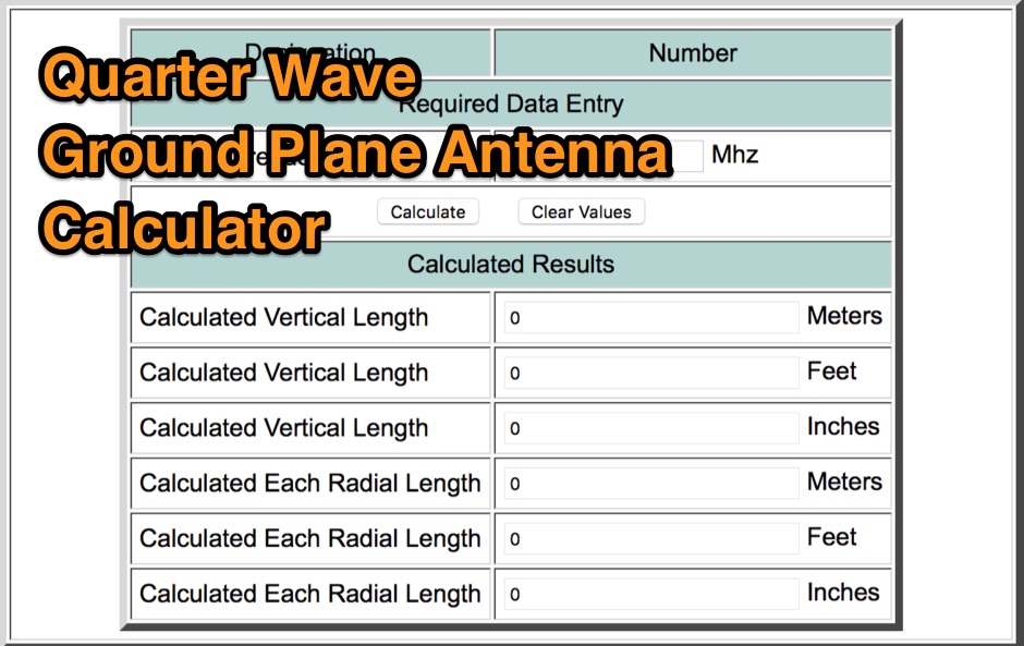 Amateur quarter wave ground plane antenna calculator, calculate vertical and radial length
 -
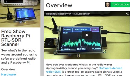 Get started with SDR using a Raspberry Pi and inexpensive RTL-SDR tuner.
 -
 End-Fed Half-Wave Antennas (EFHWAs) are analyzed for their utility in portable QRP operations, emphasizing their simplicity, efficiency, and predictable radiation patterns compared to other portable antenna types. The discussion contrasts EFHWAs with vertical antennas, random length wires, and center-fed dipoles, highlighting the common pitfalls of each, such as ground system dependency for verticals and feedline issues for dipoles. The article details the electrical half-wavelength calculation using the formula L (Ft) = 468/F(MHz) and explains how EFHWAs can be resonant on harmonic frequencies, enabling multiband operation. Various deployment configurations are presented, including the inverted L, inverted Vee, sloping wire, and vertical setups, each with specific advantages for radiation angle and polarization. For instance, a vertical EFHWA offers a low angle of radiation suitable for DX contacts without requiring an extensive ground system. The resource also addresses the counterpoise requirements, suggesting a quarter-wavelength wire or connection to a metallic structure for decoupling. A schematic diagram for a simple parallel-tuned circuit tuner, based on the _Rainbow Bridge/Tuner_ design, is provided, detailing component values for 30 and 40 meters, including a 6 microhenry toroidal inductor and a 20-100 picofarad mica compression capacitor. The tuner's adjustment process for SWR matching is also outlined.
 -
 Get the most out of the shortwave listening hobby. Follow these steps to get started with your new radio.
 -
 Publication for the video aspects of ham radio
 -
 The Powerpoint presentation below was given by Fred Hopengarten, K1VR, at the 1998 Dayton Hamvention Antenna Forum
 -
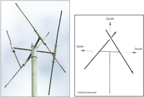 An easy to build antenna for ground reception of NOAA weather or amateur satellite signals. Double cross antenna by Gerald Martes
 -
 Simple DIY stealth apartment antenna for 20m and 40m. It is basically a ZigZag quarter wave dipole antenna
 -
 A quarter-wave vertical antenna design for HF operation offers a practical solution for radio amateurs seeking a compact and efficient multi-band radiator. This project details the construction of a 5-band HF vertical, drawing inspiration from established commercial products such as the _DX COMMANDER_ and the MV6. The design emphasizes ease of assembly and disassembly, making it suitable for portable operations or installations with limited space. The article provides insights into various construction methods and offers practical tips for building a robust yet lightweight antenna. It highlights the benefits of a vertical configuration for DX contacts, particularly on the lower HF bands, and discusses real-world performance observations. The antenna is designed to cover multiple HF bands, providing versatility for various operating scenarios. Operators can achieve significant DX results with this type of antenna, often comparable to more complex arrays, especially when deployed with an effective ground system. The project aims to empower hams to build a capable antenna without significant financial outlay.
 -
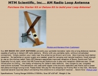 Loop Antenna Starter Kit contains detailed plans for building the MTM Scientific, Inc. loop antenna from scratch.
 -
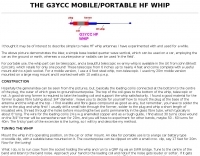 A simple base loaded quarter wave vertical, which can be used on a car or portable by G3YCC
 -
 A quarter wave vertical end-fed antenna for the 40 meters band. As all vertical antennas, also this aerial requires a good earthing system. In this project the ground is composed by twelve 4, wires buried in the lawn by using a spade to create a slit to drop the wire into.
 -
 How Ham Radio Works, by Gary Brown, Ham radio can be very portable and affordable. In this article, we will look at ham radio and show you how to get started in this wireless world
 -
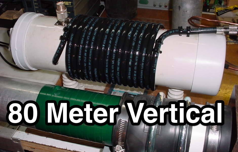 Homebrew a 1/4 wave 80 meter vertical using aluminium tubing
 -
-
 What Amateur Radio (ham radio) is. How to get started in ham radio. License requirements. Where to find instructions.
 -
 Helical antennas invented by John Kraus give a circular polarized wave. They are one of the easiest to design. Find a tube with a circumference equal to one wavelength, and wrap wire in a helix spaced a quarter wavelengt
 -
 Demonstrates the design and construction of a 9-element Yagi antenna for the **70 cm band** (432 MHz), based on the DK7ZB concept. The resource details EZNEC+ calculations for a single antenna, providing gain, sidelobe suppression, and front-to-back ratio figures. It also presents a comprehensive analysis of stacking two such antennas, including optimal stacking distance (1000 mm) and the resulting performance enhancements for the stacked array, such as an increased gain of 17.03 dBi. The article includes detailed drawings, wire file dimensions in millimeters, and azimuth/elevation plots for both single and stacked configurations. Practical construction steps are documented with original photographs, illustrating element mounting, the **28 Ohm matching system** using two quarter-wave 75 Ohm transmission lines, and the critical N-connector wiring. It also covers the iterative process of fine-tuning the driven element length to achieve a return loss of 20 dB, validating the EZNEC+ simulation results with actual measurements.
 -
 A simple quarter-wave length vertical for 40m band using a 12 m spiderpole
 -
 A multiband quarter wave vertical antenna that works on 5 bands.
 -
 NorCal, a group of some 2,000+ QRP enthusiasts started in Northern California in 1993.
 -
 This strange looking antenna is a combination of Coupled-Resonator principle by K9AY and a quarter stubs to achieve low angle radiation pattern. Designed with 4nec2 NEC based antenna modeler and optimizer for 145/220/440MHz bands
 -
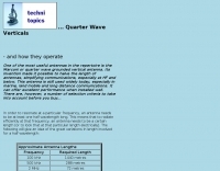 One of the most useful antennas in the repertoire is the Marconi or quarter wave grounded vertical antenna. Its invention made it possible to halve the length of antennas, simplifying communications, especially at HF and below.
 -
 Getting started with RTLSDR on MacOSX
 -
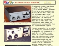 This homebrew six-meter linear amplifier started off life as a "junker" Alpha 76PA h.f. amplfier. Power output is 800W
 -
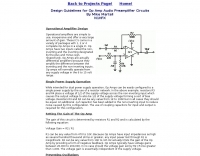 Design guidelines for Op Amp audio preamplifier circuits by Mike Martell N1HFX