Search results
Query: balanced
Links: 63 | Categories: 0
-
 The antenna is a 10 - 160 meter horizontal loop fed with 450 ohm ladder line all the way into the ham shack to an Palstar AT1500BAL balanced line antenna tuner
 -
 A balun is a device that is used at the feedpoint of a balanced antenna when an unbalanced feedline is desired to feed the antenna. Balun is a contraction for BALanced to UNbalanced.
 -
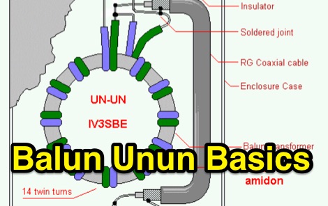 The word balun means balanced-unbalanced: it's used to adapt a balanced device to an unbalanced one, read more basic thory on Ununs and Baluns
 -
 End-Fed antennas are NOT balanced systems; but neither are verticals, ground planes, discones, windoms, zepps, Marconis, half-slopers, et al. Additionally, the low-impedance antenna port of your transmitter/receiver is not balanced.
 -
 Selecting an appropriate antenna system for shortwave broadcasting involves evaluating various types based on performance, cost, and operational parameters. This resource details the critical specifications for broadcast antennas, including average and peak power ratings, directivity, takeoff angle (TOA), horizontal beamwidth, and gain, emphasizing that a 100-kW transmitter requires an antenna rated for 150 kW average and 400 kW peak. It clarifies that low TOA signals travel thousands of kilometers, while high TOA is for local coverage, and nearly all modern shortwave broadcast antennas are horizontally polarized. The article explores specific antenna types, such as Log-Periodic Antennas (LPAs), which offer wide frequency ranges (e.g., 2-30 MHz) and directional patterns with 11 dBi gain, costing from $20K to over $100K for multi-curtain versions. Dipole arrays, also known as curtain antennas, are prevalent in international broadcasting, featuring steerable beams (±15° and ±30°) and mode-switching capabilities to alter TOA, with high/low pairs costing over $1 million. Fan dipoles are noted for omnidirectional patterns, smaller size, and lower cost for low-power applications, while rhombics, though simple, require resistive termination and incur several dB of I2R losses. Balun considerations are crucial, as most communications baluns are not rated for the higher average and peak powers of AM broadcast transmitters. Modern shortwave antennas utilize durable materials like Alumoweld wire rope for radiators and support elements, avoiding copper, fiberglass, or materials prone to stretching or deterioration. Feeder systems for high-power stations often require tapered-line baluns to convert 50-ohm unbalanced power to 300-ohm balanced for connection to the antenna.
 -
 One common challenge in antenna systems is mitigating common-mode current on the feedline, which can distort radiation patterns and introduce RF in the shack. This project details a 1:1 balun design that ingeniously avoids traditional ferrite beads, often a costly component, by substituting them with steel wool. The steel wool, when integrated into the balun's construction, effectively attenuates unwanted RF on the outer braid of the coaxial cable, ensuring that the antenna radiates efficiently and as intended. The construction involves winding coaxial cable through a PVC former, with the steel wool strategically placed to provide the necessary common-mode impedance. This method offers a practical and economical alternative for hams looking to build effective baluns without the expense or availability issues associated with ferrite cores. The design principles focus on creating a balanced feed to the antenna, crucial for optimal performance of dipoles and other balanced radiators. Experimentation with such designs can lead to improved field results, particularly for those operating with limited budgets or seeking innovative solutions for their antenna systems. The simplicity of using readily available materials like steel wool makes this a compelling build for many radio amateurs.
 -
 This document by W4HM explains the construction and usage of a 160 meter balanced coaxial receiving loop antenna, which can be easily adapted for the 40 and 80 meters bands. The content provides detailed instructions on building the antenna, its advantages, and how to optimize its performance for amateur radio operations. It is a valuable resource for radio amateurs looking to improve their receiving capabilities and enhance their overall radio communication experience.
 -
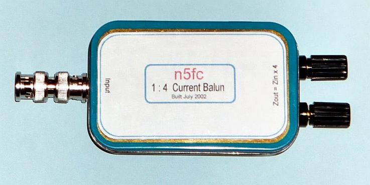
 Real 4:1 Transmission Line Balun with Balanced Load
 -
 The ZS6BKW multiband HF antenna, a design by ZS6BKW (G0GSF), functions effectively on multiple HF bands without requiring an Antenna Tuning Unit (ATU) for 40, 20, 17, 12, 10, and 6 meters. This antenna, approximately **27.51 meters** (90 feet) long with a 12.2-meter (40-foot) open-wire feeder, is a direct descendant of the _G5RV_ but offers superior multi-band resonance. It can be deployed as a horizontal dipole or an inverted-vee, with the latter requiring only a single support and maintaining an apex angle of at least 90 degrees to prevent signal cancellation. Performance data, recorded with an MFJ Antenna Analyser, indicates SWR values of 1:1 on 7.00 MHz (40m) and 14.06 MHz (20m), with SWR below 1.3:1 on 17m, 10m, and 6m. While primarily designed for these bands, the antenna can be adapted for 80m, 30m, and 15m with an ATU, preferably at the balanced feeder's base. The use of 450-ohm twin-lead for the feeder is recommended over 300-ohm for improved strength and reduced losses, especially in adverse weather conditions. This design, originally published in _RadCom_ in 1993 and featured in Pat Hawker’s "Antenna Topics," provides a compact and efficient solution for HF operation, particularly for those with limited space or resources.
 -
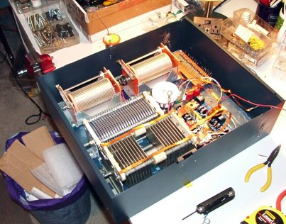
 The "EZ-Tuner" is a homebrew automatic legal-limit antenna tuner that covers all amateur HF bands from 160-10 meters. Using a T-network design and controlled by a BASIC Stamp BS2sx microcontroller, the EZ-Tuner will match at least a 16:1 VSWR for either unbalanced or balanced transmission lines.
 -
 PA0FRI's "S-MATCH ATU" published in RSGB's RadCom March 2003). The Balanced Universal ATU Photographs of ZL2ML's S-Match were added.
 -
 The Clemens match is easy to make and reliable, and is preferable to a single Gamma match as it is balanced
 -
 A simple T-network that can match any unbalanced antenna system by AA5TB
 -
 W5ALT Indoor Vertical Antenna is a base loaded vertical antenna that can be tuned on almost all HF bands by adjusting a big coil. Operating a ham radio station from an apartment in Maracaibo, Venezuela, the author demonstrates effective communication with over 100 countries using a custom-built indoor vertical antenna. Addressing common misconceptions, the design uses a balanced approach with radials and a base-loaded vertical element made from affordable materials. The antenna fits discreetly indoors, covers 6 to 40 meter bands, and achieves acceptable SWR with an MFJ tuner. Despite limited space and typical apartment challenges, the setup enables reliable DX contacts, confirmed by numerous QSL cards, proving indoor antennas can perform well in constrained environments.
 -
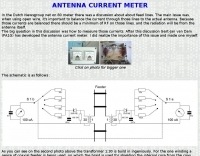
 This project is intended to aid in tuning a balanced antenna or feedline that has a high impedance 100-600 ohms
 -
 The Emtech ZM-2 Antenna Tuner is a nifty little portable transmatch for QRP (low power). It utilizes the well-known Z-match circuit, which is especially useful for balanced antennas (like dipoles and loops).
 -
 Described is a simple inverted-V antenna which, when used with a balanced ATU, can be used on all the main Radio Amateur HF bands (80, 40, 20, 15 and 10m). The cental support is made in such a way that the wire can be coiled up for storage when the antenna is taken down.
 -
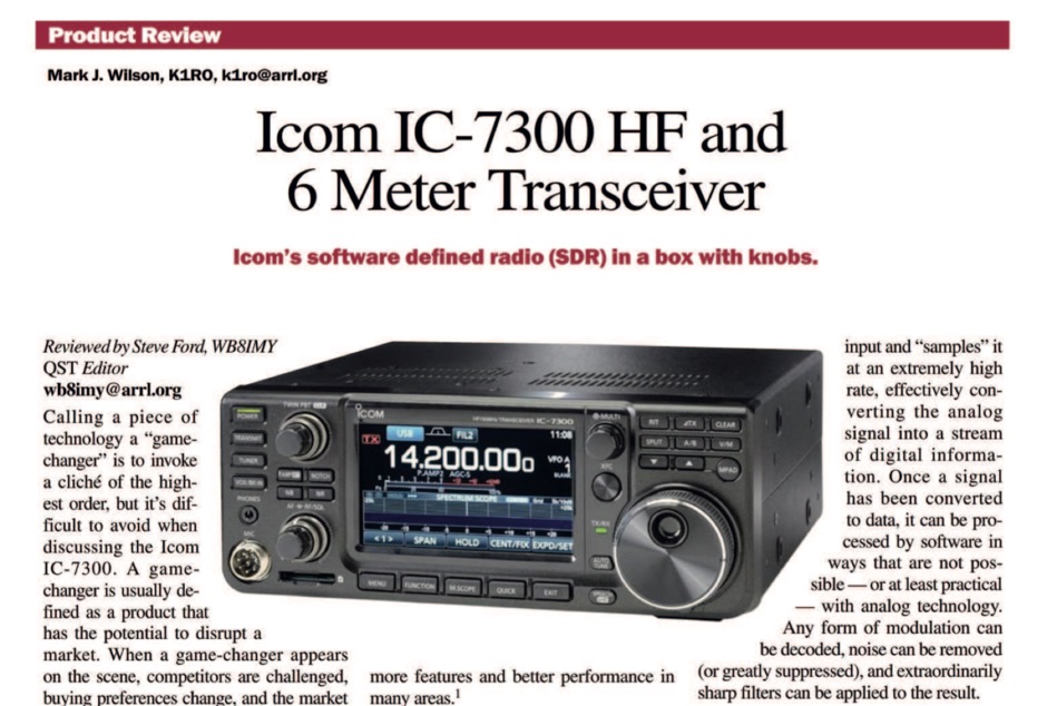 The ICOM IC-7300 is a cutting-edge HF transceiver that has garnered significant attention since its release. This review, published by ARRL in QST, provides an in-depth analysis of its features, performance, and usability. The IC-7300 is known for its direct sampling technology, which enhances its sensitivity and selectivity, making it a favorite among amateur radio operators. The review covers various aspects, including the user interface, audio quality, and overall operational capabilities, providing valuable insights for both new and experienced hams. In addition to its technical specifications, the review discusses the IC-7300's performance in real-world scenarios, such as DXing and contesting. It highlights the transceiver's ability to handle weak signals and its versatility across different modes. The review serves as a helpful guide for those considering the IC-7300 for their station, offering a balanced perspective on its strengths and potential drawbacks. Overall, this review is an essential resource for anyone interested in the ICOM IC-7300 and its place in the amateur radio landscape.
 -
 The W1TAG LF Receiving Loop is a specialized antenna project for LF reception, designed to mitigate local noise and enhance weak signal pickup on the lower frequencies. This square loop, measuring 6 feet per side, utilizes 14 turns of #12 THHN wire wound on a PVC frame, offering a robust mechanical structure. The design incorporates a series-tuned circuit with a coupling transformer, allowing for tuning from over 400 kHz down to _45 kHz_ using a switched capacitor bank. Construction details include the use of 1.5-inch PVC pipe for the frame, with specific measurements for spreaders and drilled holes for wire threading. The two 7-turn sections of wire are connected at the center, providing an option for a center tap. The loop rotates on a 1-inch steel pipe, enabling directional nulling of noise sources. The tuning unit, housed in a box clamped to the PVC, employs a 1:2 step-up transformer wound on an _FT-82-77 core_ and uses relays to switch capacitance values from 50 pF to 6400 pF, providing precise frequency adjustment. The current setup connects to the shack via 100 feet of RG-58, feeding into a W1VD-designed preamp, with plans for a balanced, shielded twisted pair cable upgrade.
 -
 Put up the longest dipole you can fit, feed it with open wire line, connect it to the balanced output of your tuner and poof! Instant multiband antenna. Is life really that simple?
 -
 The QRP choke balun described utilizes a high permeability ferrite rod and RG-174 coax, aiming to present high impedance to common-mode currents across the HF spectrum. The construction involves winding as many turns of RG-174 as possible around the ferrite rod, then encapsulating the assembly with hot glue. This design prioritizes maximizing inductance to suppress unwanted shield currents, particularly in unbalanced antenna configurations. While the balun's effectiveness is subjectively reported as good, a potential design consideration involves the dielectric properties of the hot glue. This material could increase turn-to-turn capacitance, potentially reducing the balun's performance at higher HF frequencies, though this specific aspect has not been formally tested by the author, _AA5TB_. The project serves as an illustrative example of a practical, junk-box construction rather than a rigorously engineered solution. Photographs detail the evolution of the balun, from the initial winding process to its integration within a _B&W dipole center insulator_ and final camouflaged assembly.
 -

-
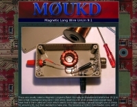 An impedance transformer (9:1) to feed a high impedance long wire (~450 ohm), down to a 50 ohm unbalanced coaxial input.
 -
-
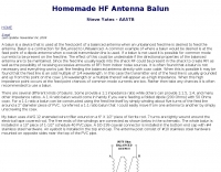
 The document provides a comprehensive overview of baluns, which are devices used to connect balanced loads, like dipole antennas, to unbalanced inputs, such as coaxial cables. It covers various types of baluns, including voltage and current baluns, and their design, construction, and testing. The text discusses the importance of baluns in preventing RF currents on coax shields and their applications in Ham radio setups. It also includes practical advice on selecting and using baluns based on antenna impedance and power ratings, along with detailed performance evaluations and construction tips for different balun configurations.
 -
 One point eight MHz to 30 MHz is the operational bandwidth for this 4:1 Ruthroff voltage balun, designed to interface an unbalanced T-Match network with a balanced antenna system. The project details the construction using a _T200-2_ powdered iron toroid core, tightly wrapped in PVC electrical tape for insulation, and wound with 17 double bifilar turns of 1.25mm enamelled copper wire. This outboard balun offers flexibility, allowing hams to trial various baluns based on antenna system and impedance characteristics, rather than integrating it directly into the tuner. The resource includes a schematic of the balun, a wiring diagram showing winding connections, and a table suggesting alternative toroid cores like the T80-2 or T400-2 with corresponding winding counts. Component sourcing is straightforward, listing items such as the _Amidon_ T-200-2 core, SO-239 connector, and a sealed polycarbonate enclosure from Jaycar. Performance evaluation was conducted using an _AIM 4170C_ antenna analyser, demonstrating efficient 1:4 voltage transformation across the specified HF spectrum. Further efficiency tests involved measuring RF power loss at various frequencies, revealing minimal loss—less than 0.7 dB from 3.6 MHz to 30 MHz, and only 2.0 dB at 1.8 MHz. These measurements, performed under ideal 50-ohm conditions, confirm the balun's effectiveness as a low-loss interface for multi-band antenna systems. The page also links to several other balun and unun projects, including 1:1 current and voltage baluns, and 9:1 voltage ununs, providing a broader context for impedance matching solutions.
 -
 This calculator is designed to give resistor values for unbalanced T-pads, and for balanced H-pads.
 -
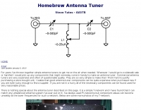
 A home made antenna tuner based on the W6JJZ basic concept that ,atches balanced loads without the use of lossy baluns, can provide band-pass filtering and harmonic attenuation.
 -
-
 CWS ByteMark's Baluns (Balanced to Unbalanced) and Ununs (unbalanced to unbalanced) transformers are developed jointly with Dr. Jerry Sevick, W2FMI, who is known worldwide for his work on transmission line transformers
 -
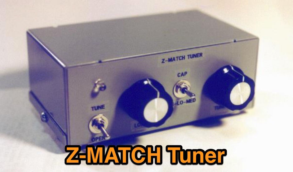
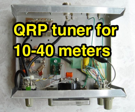
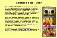 A small Z-Match tuner, BLT, Balanced Line Tuner is a simple Z-Match tuner that works from 10-40 meters
 -
 Stop common-mode current when transmitting with an end-fed antenna. Unbalanced antennas are very prone to currents on the outside of the coax.
 -
-
 Balanced feed with coaxial line by John F. Clemens W9ERN
 -
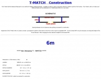 The T-Match with its balanced feed point is one method of feeding a Balanced Dipole.
 -
 Details the construction of an **HF converter** designed by M1GEO, George Smart, specifically to extend the frequency range of the FunCube Dongle Pro (FCD) for amateur radio reception. The FCD natively covers 64 to 1,700 MHz, but this project enables reception from 0 Hz to 64 MHz by up-converting signals to the FCD's operational range. It employs a **double-balanced mixer** with a 100 MHz local oscillator (LO) to translate incoming HF signals; for instance, a 1 MHz signal appears at 101 MHz within the FCD's passband. The design incorporates a 7th-order Chebyshev low-pass filter with a 62 MHz cutoff frequency at the input to mitigate image frequencies, ensuring cleaner spectral presentation. George provides the schematic, PCB masks, and Gerber files for replication, noting that Far Circuits also offers PCBs. The resource includes test results for the low-pass filter and measurements of LO leakage, identifying -36.8 dBm at 100 MHz as a potential sensitivity concern. M1GEO discusses potential improvements, such as adjusting the mixer's LO drive, adding a balance pot, or incorporating a post-mixer high-pass filter to reduce LO breakthrough. Audio recordings from 40m and 17m demonstrate the converter's performance with WRplus SDR software.
 -
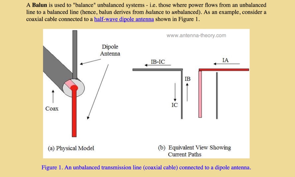 This article describe the principles of baluns when referred to devices used to balance unbalanced systems, like a coax cable and a dipole antenna
 -
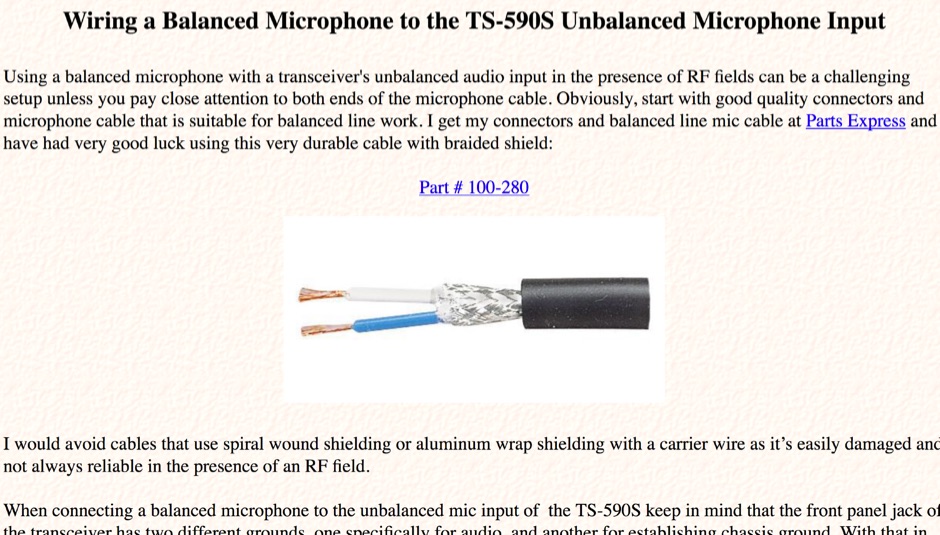 Wiring a Balanced Microphone to the TS-590S Unbalanced Microphone Input
 -
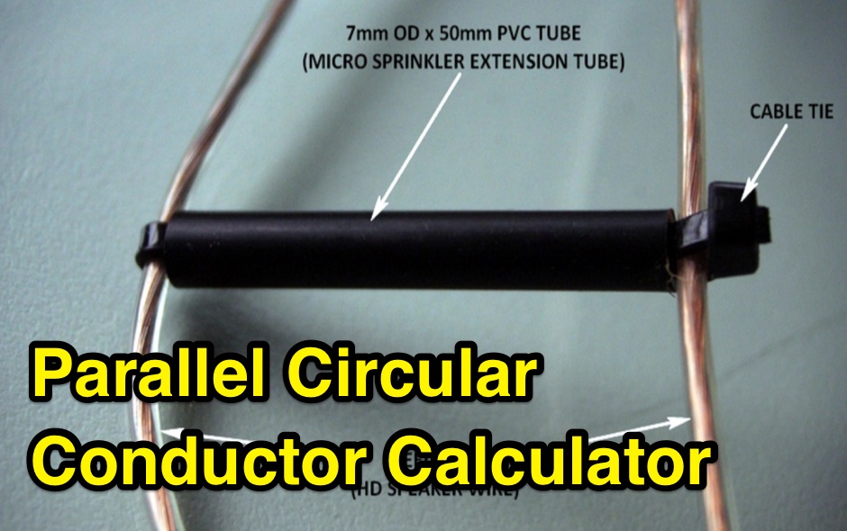 Design a parallel circular wire balanced transmission line with this online calculator. This calculator is a tool for designing balanced transmission lines with a specific desired characteristic impedance Zc and made of parallel circular conductors of a given diameter d.
 -
 Presents a concise guide for Amateur Radio operators participating in Jamboree-on-the-Air (JOTA), an annual event connecting approximately 500,000 Scouts and Guides worldwide via ham radio. The resource details how to initiate a voice contact, including the use of "CQ Jamboree JOTA" and proper signal reporting with the RST system. It also outlines the typical exchange information, such as name, QTH, Scout rank, and age, encouraging participants to practice their responses. Authored by Bill Wetherill, N2WG, the brochure provides a practical phonetics chart and a comprehensive Morse code dictionary, including punctuation and prosigns like AR and SK. It clarifies rules for third-party operation under the direct supervision of a licensed operator, noting restrictions on international contacts without specific government agreements. Additionally, the guide lists recommended World Scout Frequencies for SSB and CW across 80, 40, 20, 17, 15, 12, and 10 meters, emphasizing courteous operating procedures. It includes a section on common Q-signals like QRM, QRN, and QSL, alongside the Amateur's Code, which stresses considerate, loyal, progressive, friendly, balanced, and patriotic conduct.
 -
 Moxon is a rectangle shaped directional antenna, originally designed by Les Moxon G6XN. There are couple of advantages of using this antenna. It is small in size, Easy to mast, Balanced to 50 Ohms, Near 1:1 SWR, Excellent Front to Back (F/B) ratio, Large bandwidth
 -
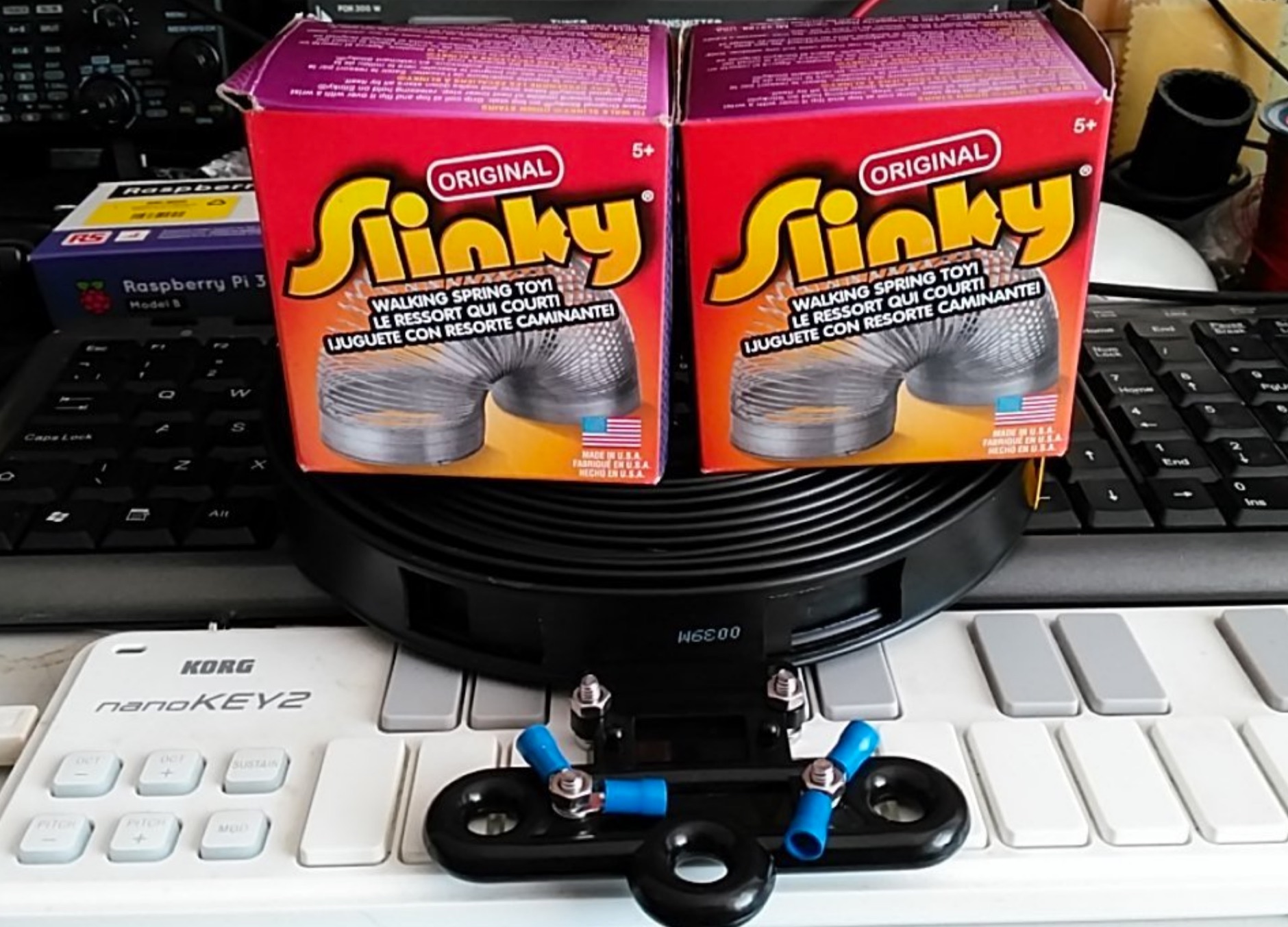 An home made doblet antenna made with two Slinkys that are aproximately five meters in length connected with a twin-feed connected to a balanced ATU
 -
 1500 watts PEP SSB is the power handling capability of the MFJ-989C HF Antenna Tuner, a popular choice among amateur radio operators. Users have shared a wide range of experiences, with some praising its durability and performance over decades of use, while others criticize its build quality and accuracy. The tuner features a built-in dummy load, SWR-wattmeter, and a balun for balanced line feeders, making it versatile for various antenna setups. However, discrepancies in RF power readings and SWR measurements have been noted, with some users finding the dual scale meter to be off by about 20% compared to a Bird wattmeter. Long-term users report that the MFJ-989C performs well with proper antenna setups, but caution against tuning at high power without initial adjustments at lower power levels. Some have experienced issues such as arcing when exceeding 400 watts, while others have had no problems even at higher power levels. The roller inductor and capacitors are functional, though some users have had to perform maintenance like tightening screws or cleaning components to ensure reliable operation. Despite mixed reviews, the MFJ-989C remains in production, suggesting continued demand. It's a tuner that requires careful handling and possibly some DIY fixes to achieve optimal performance.
 -
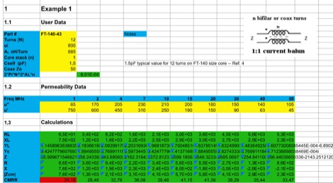 This EXCEL Program Worksheet calculates the common-mode impedance of a 1:1 Guanella (current) balun which is placed at the feed point of a balanced antenna system fed via coax.
 -
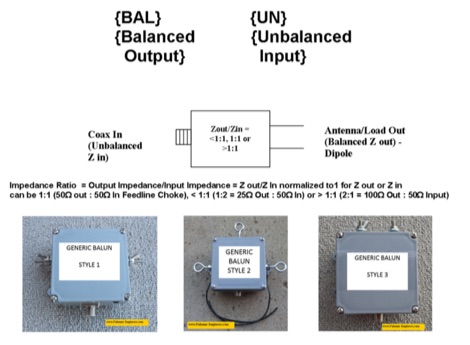 If you ever asked if you need an Unun or a Balun this article is for you. The right question should be do I need a feed line choke or an impedance transformer whose output is configured as balanced or as unbalanced. An impedance transformer can be configured as a voltage transformer or as a current transformer.
 -
 The resource, "Conventional Use of Transmission Line," meticulously details the operational principles of transmission lines, emphasizing the Transverse Electromagnetic (TEM) mode of energy transfer. It clarifies that for a line to function purely as a transmission line, all currents must be confined internally, with external fields ideally zero. The discussion differentiates between balanced and unbalanced lines, asserting that while both require equal and opposite currents within the conductors, the key distinction lies in the voltage relationship of each conductor to the surrounding environment. It highlights that a good antenna pattern does not inherently confirm proper feeder balance, and that common-mode currents can lead to RF in the shack and increased noise levels, even without pattern distortion. The article further explains that a transmission line can become a radiating conductor if energy is applied in a non-TEM mode, leading to common-mode issues. It cites classic texts like Jordan and Balmain's "_Electromagnetic Waves and Radiating Systems_" and Kraus's "_Antennas_" to support its definitions of TEM mode operation. The content also explores non-transmission line applications of parallel or concentric conductors, such as _coaxial dipoles_ and _folded dipoles_, which intentionally operate in non-TEM modes for antenna functionality. The author, _W8JI_, stresses that simply measuring equal currents is insufficient to confirm a balanced feeder; phase and voltage balance to ground are equally critical.
 -

-
 The Tri-pole antenna, a clever modification of a standard dipole, allows for dual-band operation by integrating a third element. This design effectively shortens the overall dipole length by 10 to 20 percent, simplifying antenna rotation and offering a compact footprint. KK4OBI's article delves into the operational principles, using a 6 and 10-meter Tri-pole as a primary example, and provides comprehensive instructions for constructing any Tri-pole antenna within the 6 to 15-meter range. Key to the Tri-pole's performance is its off-center feed, necessitating a common mode choke at the feed point for optimal tuning and reduced noise. The author outlines a methodical approach to determining element dimensions, starting with a vertical element frequency calculated as 0.47 times the sum of the desired upper and lower band frequencies. This calculation, along with K-values derived from trend lines, guides the initial lengths for the horizontal arms, demonstrating how a 10m-6m Tri-pole can achieve a total horizontal length 78% shorter than a conventional 10-meter dipole. Tuning and balancing are critical, with the article detailing adjustments to arm lengths and the vertical element to achieve balanced SWR values, as validated through 4NEC2 simulations. Radiation patterns are analyzed at various elevations, showing gains around 5.7 dBi and favorable take-off angles for DX contacts. Construction details specify aluminum tubing dimensions, U-bolts, and an SO-239 connector, emphasizing the importance of a ferrite-based choke for wideband operation.
 -
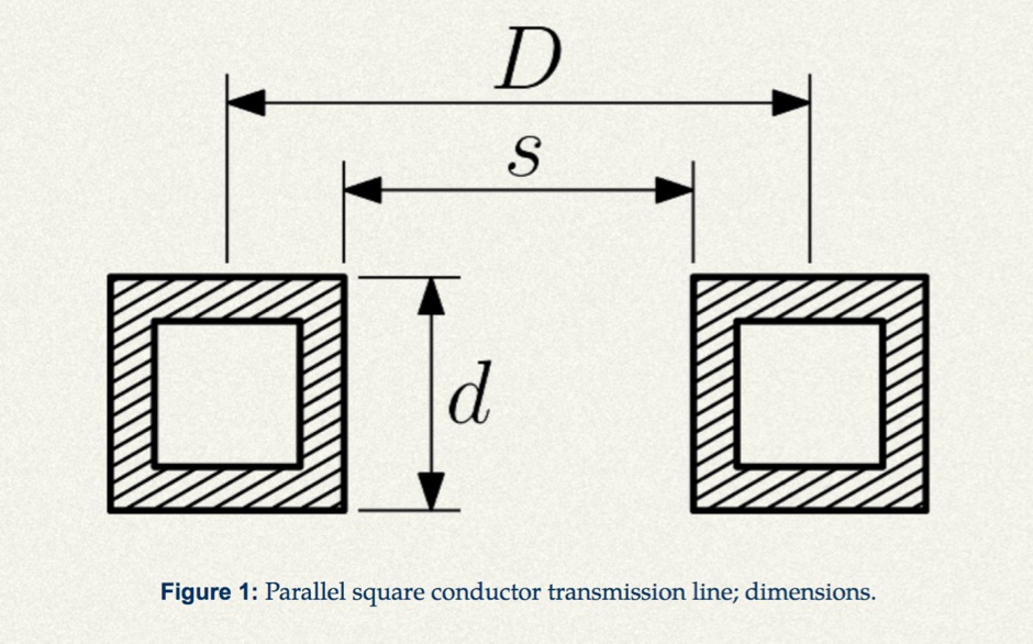 Design a parallel square stock balanced transmission line with this calculator.
 -
 256 memories enable the _AT-AUTO_ to recall settings across multiple bands, making it efficient for operators who frequently change frequencies. The tuner is compatible with various antennas and amplifiers, such as the Mercury LUX, and integrates seamlessly with radios like the FLEX 6400 using an RS232-USB connection. This integration allows the tuner to follow frequency changes without additional input, enhancing operational efficiency. Despite being out of production, the _AT-AUTO_ remains supported by Kessler Engineering, which offers firmware updates and repair services. The tuner features a cross-needle SWR meter, providing quick visual feedback during tuning. It also includes a QRO keyline circuit to protect amplifiers during tuning. Users appreciate the tuner's ability to track radios via CAT control, avoiding automatic tuning during QSOs, a common issue with other models. The _AT-AUTO_ is praised for its durability and performance, with many users noting its reliability over years of use. Its ability to handle legal limit power and its balanced line output make it a versatile choice for serious operators. Although it lacks some features like multiple coax outputs found in other models, its robust build and continued support make it a valuable tool for HF enthusiasts.