Search results
Query: city
Links: 219 | Categories: 2
-
 This resource provides a detailed guide on constructing a J-pole antenna specifically for the 2 meter band, which is popular among amateur radio operators. The article outlines the materials needed, including various sizes of aluminum pipes and PVC, as well as the tools required for assembly. It emphasizes the simplicity and effectiveness of the J-pole design, making it an ideal choice for newcomers to amateur radio. The instructions are straightforward, allowing users to build the antenna in less than an hour, and include tips for tuning the antenna for optimal performance. In addition to the construction details, the resource includes practical advice on the assembly process, such as how to cut and join the pipes, as well as how to mount the SO239 connector. The author shares personal experiences and insights on achieving a low standing wave ratio (S.W.R.) and suggests modifications for creating bi-band or tri-band J-pole antennas. This comprehensive guide is enriched with photographs that illustrate the construction steps, making it easier for users to follow along and successfully build their own J-pole antenna.
 -
 The G5RV antenna, with an overall length of **31.10m (102ft)**, functions as a 3/2-wave on 20 meters when installed horizontally at 12m (39ft), exhibiting a resonant frequency of 14.150MHz and an approximate resistance of 80 ohms. Its 10.36m (34ft) stub line, designed as a 1/2-wave on 14.150MHz with a 0.97 velocity coefficient, acts as an impedance transformer across other bands, aiming for multiband operation without traps. On 20m and higher frequencies, the G5RV demonstrates improved gain compared to a standard dipole, attributed to the _collinear effect_ from multiple 1/2-waves along the wire. The original design sought a multiband solution for limited spaces, often requiring an Antenna Tuning Unit (ATU) for effective operation across bands like 80, 40, 30, and 20m, particularly with modern solid-state PAs. Variants, such as the F8CI modification, incorporate a 1/4 current balun at the stub line's base for symmetrical-to-asymmetrical transition, known as a _remote balun_. Proper flat-top or inverted-V installation is critical for maintaining symmetry and collinear gain, with inverted-V apex angles below 120° progressively diminishing higher-band performance.
 -
 This resource details the fundamental aspects of deploying longwire antennas, emphasizing ease of construction and installation for shortwave listening (SWL) and broadcast reception. It covers wire gauge selection, suggesting 14 to 24 AWG for general use, with heavier gauges (14-20 AWG) for permanent outdoor installations. Guidance is provided for various deployment scenarios, including indoor setups where the wire can be run around a room, temporary outdoor installations from balconies using light 18-24 AWG wire, and permanent outdoor configurations requiring higher placement and slack for tree movement. Feeding methods are discussed, recommending coaxial cable (50-75 ohms) to mitigate man-made interference, with instructions for connecting only the center conductor to the longwire. Safety precautions are highlighted, particularly avoiding contact with power lines and conductive materials, and managing static electricity buildup by unplugging the antenna after use and bleeding off charges before connection. The article also advises against using outdoor longwires during thunderstorms or snowstorms due to static and lightning risks. Optimal height considerations are presented, advocating for the highest safe placement, ideally a couple of feet above underlying structures, to maintain free air space. The text mentions a personal setup with one end at a roof peak (20 feet) and the other at a 17-foot mast, illustrating practical deployment without strict height requirements beyond safety and clearance.
 -
 Listen to Jersey City cops fight crime, live and uncensored. Anything can happen out on the streets of the city
 -
 Details the construction of a J-vertical antenna specifically for the 10-meter band, offering a practical alternative to a _Slim Jim_ design for 28 MHz. The resource outlines the use of aluminum tubing for the half-wave vertical section and coaxial cable for the quarter-wave matching section, providing specific calculations for element lengths based on frequency and coaxial cable velocity factor. It contrasts the performance of the J-vertical with center-fed dipoles and end-fed verticals, noting superior results in previous comparisons. The article further presents a more recent iteration of the J-vertical, constructed using a fiberglass pole and insulated wire, with updated dimensions for 28.8 MHz. It includes practical advice on weatherproofing connections and securing the antenna for durability against adverse conditions, referencing the survival of an original _J Vertical_ during 110 MPH winds in 1987. The SWR performance is reported as 1.1:1 at 28.6 MHz, maintaining below 1.5:1 across 28.3 to 29 MHz.
 -
 Over 200 Telnet DX cluster entries are meticulously cataloged, each providing the cluster's callsign, IP address or hostname, and the specific port for connection. The resource details the geographic location for each cluster, often including grid square information or city/country, which is crucial for operators seeking regional or local spotting networks. For instance, **AB5K** offers both worldwide and USA/Canada-only spot feeds, while **K2LS** explicitly limits spots to USA/Canada/Caribbean Zones 1-8, excluding chat messages. The compilation serves as a practical reference for amateur radio operators who utilize traditional Telnet clients for real-time DX spotting. It presents a raw, unadorned list, prioritizing direct access information over elaborate interfaces. This format allows for quick integration into logging software or terminal programs that support Telnet connections. Distinctively, the resource focuses exclusively on Telnet access, differentiating it from web-based or aggregated cluster services. The sheer volume of listed clusters, spanning continents from Europe and North America to Asia and Oceania, makes it a robust tool for DXers and contesters aiming to monitor propagation and identify rare DX stations across various bands.
 -
 Listen to the Baltimore City Police Live Scanner Radio Feed.
 -
 The project details a DIY SWR/Wattmeter designed around an _Arduino Uno_ shield, providing capabilities to measure RF power from 2 to **200 watts** and Standing Wave Ratio (SWR) for HF amateur radio bands. This construction features a compact design, integrating the measurement circuitry directly onto a custom PCB that interfaces with the Arduino Uno microcontroller. Key components include a directional coupler for sensing forward and reflected power, precision rectifiers, and analog-to-digital conversion for processing RF signals. The Arduino firmware handles calibration, calculations, and displays the results on an integrated LCD, offering real-time feedback on antenna system performance. The design prioritizes simplicity for homebrewers. Performance specifications indicate accurate readings within the **2-200W** power range, suitable for typical QRP to medium-power HF operations. The project provides schematics and a basic overview of the software logic.
 -
 This Vertical antenna design by David Reid for lower bands focuses on achieving effective DX communication by optimizing the antenna low-angle radiation for long-distance contacts. The design incorporates techniques like linear loading and capacity hats to reduce the antenna's height while maintaining performance, especially on 40m and 80m bands. Building a solid ground plane and using quality materials ensure efficiency and durability. Although vertical antennas can be complex to build, this project simplifies the process, making it accessible for ham operators seeking strong, reliable signals.
 -
 Live streaming audio of VHF marine radio channels 05A, 16, and 22A from NJ and NY City
 -
 An efficient program to calculate dimensions of coax dipoles, or bazooka antennas considering velocity length of different coax cables. Express dimensions in feet/inch and meters/cm. Freeware by VE3SQB
 -
 A Kenwood R-5000 communications receiver located in Salt Lake City that you can remotely control and receive S-Meter readings and audio from via a web browser.
 -
 ZZ Wave Net is a 40 & 80 meter full wave loop designed to fit on a city lot. ZZ Antenna is a folded dipole bent into an inverted V loop
 -
 Located in Big Bear City, CA (Shay Meadow). Streaming 24/7 since 2002 the Big Bear Scanner is providing the latest realtime audio from Big Bear City Fire, San Benardino National Forest, CalFire, San Bernardino County Fire, CHP, Lake Patrol, and much more!
 -
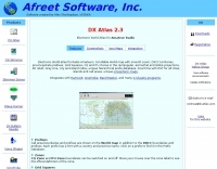 Electronic World atlas for radio amateurs. DXCC and province prefixes, CQ and ITU Zones in the rectangular and azimuthal projections, continuous zoom and scrolling, Gray Line, city and island index, unique hierarchical prefix database. COM/OLE Automation for easy integration with 3-rd party programs.
 -
 One common challenge in antenna systems is mitigating common-mode current on the feedline, which can distort radiation patterns and introduce RF in the shack. This project details a 1:1 balun design that ingeniously avoids traditional ferrite beads, often a costly component, by substituting them with steel wool. The steel wool, when integrated into the balun's construction, effectively attenuates unwanted RF on the outer braid of the coaxial cable, ensuring that the antenna radiates efficiently and as intended. The construction involves winding coaxial cable through a PVC former, with the steel wool strategically placed to provide the necessary common-mode impedance. This method offers a practical and economical alternative for hams looking to build effective baluns without the expense or availability issues associated with ferrite cores. The design principles focus on creating a balanced feed to the antenna, crucial for optimal performance of dipoles and other balanced radiators. Experimentation with such designs can lead to improved field results, particularly for those operating with limited budgets or seeking innovative solutions for their antenna systems. The simplicity of using readily available materials like steel wool makes this a compelling build for many radio amateurs.
 -
 A 10-meter J-Pole antenna, detailed in QST February 1950, offers a straightforward solution for hams operating with restricted space. This design, originally presented by W1BLR, is a **half-wave radiator** fed by a quarter-wave matching stub, providing a low-angle radiation pattern beneficial for DX. The article describes building the antenna from readily available materials like copper pipe, emphasizing its simplicity and effectiveness for **single-band operation**. The J-Pole's inherent design provides a good impedance match to 50-ohm coaxial cable without the need for an external tuner, a significant advantage for portable or minimalist stations. Its nondirectional pattern ensures coverage in all directions, making it a versatile choice for general operating on the 28 MHz band. The construction plans are clear, allowing even those with basic workshop skills to assemble a functional antenna.
 -
 A 2-meter Turnstile antenna, detailed for amateur satellite communication, offers a straightforward build for those looking to engage with orbiting transponders. The author, WB8ERJ, shares his personal design and construction methods, emphasizing the antenna's simplicity and effectiveness for LEO (Low Earth Orbit) satellite work. This design provides a circularly polarized signal, crucial for mitigating _Faraday rotation_ and signal fading often encountered with linearly polarized antennas when tracking satellites. Construction involves readily available materials like PVC pipe and copper wire, making it an accessible project for many hams. The article includes practical advice on element spacing and feed point considerations, drawing from the author's hands-on experience in the shack and field. It highlights the antenna's utility for receiving signals from various amateur satellites, including the popular AO-91 and AO-92. The Turnstile's inherent omnidirectional pattern in the horizontal plane, combined with its circular polarization, yields consistent signal reception, often resulting in **stronger decodes** and **more reliable contacts** compared to basic dipoles or verticals.
 -
 The homemade CW paddle key design, inspired by a QRP homepage, utilizes soldered PC board material for its construction. The builder, DL5NEJ, modified an existing design to achieve a smaller footprint, preferring a compact setup for portable operations. This paddle was specifically built to complement a Wilderness Radio SST20 QRP transceiver kit, demonstrating its suitability for low-power operations. The project details suggest a straightforward assembly process, with the primary components being readily available PC board scraps. The design emphasizes simplicity and functionality, aiming to provide a reliable keying experience comparable to commercial paddles like the Bencher. Performance evaluations indicated the simple paddle operates effectively, prompting further exploration into similarly minimalist QRP rig designs. Additional construction details for a similar paddle are available from PA0CMU.
 -
 End-Fed Half-Wave Antennas (EFHWAs) are analyzed for their utility in portable QRP operations, emphasizing their simplicity, efficiency, and predictable radiation patterns compared to other portable antenna types. The discussion contrasts EFHWAs with vertical antennas, random length wires, and center-fed dipoles, highlighting the common pitfalls of each, such as ground system dependency for verticals and feedline issues for dipoles. The article details the electrical half-wavelength calculation using the formula L (Ft) = 468/F(MHz) and explains how EFHWAs can be resonant on harmonic frequencies, enabling multiband operation. Various deployment configurations are presented, including the inverted L, inverted Vee, sloping wire, and vertical setups, each with specific advantages for radiation angle and polarization. For instance, a vertical EFHWA offers a low angle of radiation suitable for DX contacts without requiring an extensive ground system. The resource also addresses the counterpoise requirements, suggesting a quarter-wavelength wire or connection to a metallic structure for decoupling. A schematic diagram for a simple parallel-tuned circuit tuner, based on the _Rainbow Bridge/Tuner_ design, is provided, detailing component values for 30 and 40 meters, including a 6 microhenry toroidal inductor and a 20-100 picofarad mica compression capacitor. The tuner's adjustment process for SWR matching is also outlined.
 -
 The Buddipole website showcases a range of portable amateur radio antenna systems, including the **Buddipole**, Mini-Buddipole, Buddistick PRO, and BuddiHEX, designed for rapid deployment and multi-band operation from 40 meters to 2 meters. Each product page details specifications, operational modes (dipole or vertical), and compatible accessories like tripods, masts, and baluns. The site also features portable DC power management systems such as the PowerMini 2 and PowerPlus, which include integrated battery chargers and solar controllers, catering to off-grid or field day setups. Instructional videos demonstrate antenna assembly, tuning, and deployment techniques for various configurations, including the VersaTee vertical and Mini-Buddipole. Customer testimonials and DXpedition highlights, such as operations from Montserrat (VP2M) and Dominica (J38), provide real-world examples of the equipment's performance in challenging environments. The company, established in 2001, emphasizes modularity, versatility, and efficiency in its product line, all manufactured in the USA. Shipping information, a 30-day return policy with no restocking fee, and contact details for their Heber City, Utah facility are clearly presented. The site serves as a direct sales portal, offering a comprehensive catalog of antennas, power solutions, and components for portable amateur radio enthusiasts.
 -
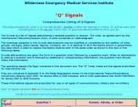 This resource presents over 100 Q-signals, each with its corresponding question and answer format, as standardized by the International Telecommunication Union. The content delineates how these abbreviations can be expanded with additional groups, call signs, place names, or numerical data to provide specific context. It clarifies that a question mark following an abbreviation or its complementary information transforms it into a query. The document highlights that these operating signals, or Op Sigs, are prescribed for international use across all communication types, including military and non-military applications. It references their inclusion in Appendix 9 to the Radio Regulations Annex of the International Telecommunications Convention (Atlantic City) 1947 for QRA to QUZ blocks, and ICAO publications Dec 6100-COM/504/1 for QAA to QNZ blocks. The page specifically marks Q-signals of particular interest to amateur radio operators in red. The utility of Q-signals for concise communication in radiotelegraphy is evident, providing a structured method for conveying complex information efficiently. The resource serves as a practical reference for operators needing to quickly interpret or formulate messages using standardized codes, particularly beneficial for CW operation and international contacts.
 -
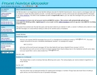 Approximately 400 kHz is the primary frequency for Navtex broadcasts, a crucial maritime safety information system. This legacy software, _Frisnit Navtex Decoder_ version 2.1.5, provides a means to decode these messages directly from an amateur radio receiver's audio output, fed into a PC's microphone input. It operates by processing the audio stream, extracting the FSK (Frequency Shift Keying) data, and presenting the decoded text on a Windows platform. Despite being unsupported and no longer under active development, the application remains functional across a wide range of Microsoft operating systems, from _Windows 95_ through _Windows 11_. Its utility lies in offering a straightforward, no-cost solution for hams and SWLs interested in monitoring Navtex transmissions without specialized hardware. The software's design focuses on simplicity, allowing users to quickly set up and begin decoding maritime weather forecasts, navigation warnings, and other safety-critical information. It leverages the PC's sound card, making it accessible with minimal additional equipment beyond a receiver capable of tuning to the Navtex frequencies.
 -

-
 Constructing a Lindenblad antenna for 137MHz NOAA satellite reception involves specific design considerations for optimal performance. The resource details the use of 4mm galvanised steel fencing wire, 300-ohm television ribbon cable, and wood/plastic components for the antenna structure. Key dimensions for a 137.58MHz-resonant antenna are provided, derived from the ARRL Satellite Handbook, specifying s, l, w, and d as 42, 926, 893, and 654mm respectively. The antenna is designed for Right Hand Circularly Polarised (RHCP) signals, requiring the four folded dipole elements to be tilted clockwise by 30 degrees. A significant aspect covered is impedance matching between the antenna's 75-ohm impedance and a typical 50-ohm receiver input. A twelfth-wave matching transformer, constructed from 117mm sections of 50-ohm RG-58 and 75-ohm RG-59 coax with a 0.66 velocity factor, is described. The article also addresses coaxial cable and connector selection, recommending 75-ohm Type-N connectors for RG-6 cable in professional setups and F56/F59 connectors for general use, while strongly advising against PL-259/SO-259 connectors for VHF. Strategies for mitigating Radio Frequency Interference (RFI) are discussed, including antenna placement to shield from local TV transmitters and the use of commercial or DIY band-pass filters, such as cavity resonators or helical notch filters, along with ferrite chokes on coaxial cables. Antenna orientation is explored, noting the Lindenblad's 'cone of silence' directly overhead and its maximized sensitivity towards the horizon. An experimental vertical tilt of 90 degrees is presented as a method to improve overhead reception and reduce interference from strong horizontal signals, particularly relevant in high RFI environments like the Siding Spring Observatory site.
 -
 This resource details the computer-optimized design of the _ZS6BKW_ multiband dipole, an evolution of the classic _G5RV_ antenna. It begins by referencing the original 1958 RSGB Bulletin article by Louis Varney G5RV, explaining the operational principles of the G5RV's flat-top and open-wire feedline on 20m and 40m, noting its impedance transformation characteristics for valve amplifiers of that era. The article then transitions to the rationale for optimizing the design for contemporary solid-state transceivers requiring a 50 Ohm match. The core of the project involves using computer modeling to determine optimal lengths for the flat-top and matching section, aiming for a VSWR of less than 2:1 on multiple HF bands. It discusses the process of calculating feedpoint impedance based on antenna length and frequency, referencing professional literature from Professor R.W.P. King at Harvard University. The analysis also considers the characteristic impedance (Z(O)) of the open-wire line, identifying a broad peak of adequate values between 275 and 400 Ohms. Specific design parameters for the improved ZS6BKW are presented, including a shorter flat-top and a longer matching section compared to the original G5RV, with a velocity factor of 0.85 for the 300 Ohm tape. The article confirms acceptable matches on 7, 14, 18, 24, and 28 MHz bands when erected horizontally at 13m, and also discusses performance in an inverted-V configuration, noting frequency shifts. The author, Brian Austin ZS6BKW, emphasizes the antenna's suitability for modern 50 Ohm coaxial cable without a balun.
 -
 A table with Loss in DB/100m , Max power in Watts, Diameter in mm , Velocity factor (VF) expecially in VHF UHF and Microwave
 -
 The Thracian Rose Club has been created in the Roses' City Kazanlak (Bulgaria) in 1993. Its main goal is to promote contacts within the radio community members (HAM, CB and SWL).
 -
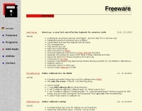 Demonstrates a very fast and effective logbook solution for amateur radio, **HAM-LOG** by HB9CQV, which operates as freeware and supports multiple languages including German and English. This application is designed to be self-running, even from USB devices, making it a portable option for hams on the go. Its database capacity is practically unlimited, capable of handling up to a billion QSOs, a significant advantage for active DXers and contesters. The software offers multi-user networking capabilities and integrates with popular digital mode programs like MixW2, FLDigi, and MMVARI through DDE connections or clipboard/INI-file transfers. It streamlines QSO logging by saving entries directly from these programs and supports import/export via **ADIF** for compatibility with other tools such as MMSSTV. HAM-LOG also connects to DX Atlas and Ham-Cap for enhanced operational awareness. Further enhancing its utility, HAM-LOG includes automatic callsign lookup on QRZ.com and supports eQSL.cc for electronic QSLing. The resource also details two smaller utilities: an Online Callbook DLL for MixW, which automatically populates names from QRZ.com into MixW log entries, and an Online Callbook LookUp command-line tool that writes callsign and name data to an INI-file, both requiring QRZ.com credentials.
 -
 The Bundesnetzagentur's online tool provides a direct interface for searching **German amateur radio callsigns**, enabling users to retrieve specific details associated with licensed operators. The system utilizes a web-based form where users input a callsign to query the official German amateur radio database. This resource is built on Microsoft Visual Studio .NET 7.1 with Visual Basic .NET 7.1, indicating a mature and stable backend for data retrieval. This callsign lookup service facilitates rapid verification of German stations, which is particularly useful for **DXers** confirming contacts or for contesters needing to cross-reference logs. Unlike broader international callbooks, its focused scope on German licensees ensures high accuracy and direct access to official data. The tool's simplicity and direct functionality make it an efficient utility for any amateur radio operator interacting with German stations.
 -
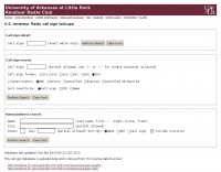 The U.S. Amateur Radio Callsign Lookup service, hosted by the University of Arkansas at Little Rock (UALR), offers a direct interface for querying the FCC's amateur radio license database. This resource is specifically designed for rapid retrieval of licensee information, including callsign, name, address, license class, and expiration date, all critical data points for QSLing and contact verification. The underlying database is refreshed daily, ensuring that the presented information reflects the most current FCC licensing records available. This service distinguishes itself by its direct reliance on official FCC data, processed and maintained by a university institution, which lends a degree of authoritative accuracy to its lookups. Users can input a specific callsign to instantly access detailed license particulars, facilitating efficient station identification and record-keeping for DXers and contesters alike. The daily update cycle minimizes discrepancies often found in less frequently synchronized callbook services. The UALR callsign lookup functions as a straightforward, no-frills utility, prioritizing data integrity and accessibility for the amateur radio community. Its operational simplicity and consistent data refresh schedule make it a reliable reference for verifying U.S. amateur radio licenses.
 -
 Largest general-purpose ham radio club in Twin Cities. Three repeaters, fully equipped two position HF club station, contesting, field day, and more.
 -
 Radio City features a wide selection of amateur radio equipment from Kenwood, Icom, Yaesu, MFJ and a host of other manufacturers. Visit the store in Mounds View or shop here, online.
 -
 United States Scanner Frequencies, Phone Numbers, and IP Addresses
 -
 This simple 30m QRSS beacon is built entirely out of junkbox parts, the only component purchased specifically for this project was the 10,140kHz crystal. Hans Summers' 30m QRSS beacon project emphasizes simplicity and low cost, built almost entirely from reused parts. Key components include a 10,140kHz crystal, a 2N3904 transistor from a broken DVD player, and an ordinary LED used for frequency shift. The oscillator is stabilized in a polystyrene box, with power amplification driven by recycled copper PCB. Output power peaks at 360mW, and a custom 50-ohm dummy load manages heat. Though aesthetically unconventional, the beacon works effectively, fulfilling the project's low cost aim.
 -
 This design was adapted from an article in the ARRL Handbook and built with simplicity and duplicity in mind. This antenna is a vast improvement over a standard dipole with a forward gain of around 8db with a front to back ratio of 10db.
 -
 A copper pipe Hentenna for 144 MHz. The Hentenna, a compact, high-gain loop antenna developed in Japan in the 1970s, offers approximately 5.1 dBd gain, comparable to a three-element Yagi. Adapted for 2 meters, it is crafted from copper pipe for simplicity, affordability, and broadband performance. Requiring no feed-point tuning, its construction involves soldering standard copper fittings. Installation demands non-conductive materials to minimize signal disruption. Versatile for vertical or horizontal polarization, it is ideal for FM, repeater, SSB, or CW applications. This design emphasizes practicality and performance for amateur radio enthusiasts
 -
 Sioux City Tri-State Area Fire/EMS, Sheriff, Police and Highway Patrol Live Audio Feed. Listen Sioux City IOWA live scanner
 -
 OPCLOG provides a straightforward logging solution for amateur radio operators, enabling the systematic recording of contacts. The software primarily focuses on basic QSO management, allowing users to input essential contact details such as callsign, date, time, frequency, and mode. Its core utility lies in its ability to export log data in the _ADIF_ (Amateur Data Interchange Format) standard, which is crucial for interoperability with other ham radio applications and services. This ADIF export functionality facilitates the creation of personalized QSL cards, streamlining the process for operators who prefer custom designs over generic templates. The program's design emphasizes ease of use for individual station logging, rather than complex contest or DXpedition management. It offers a practical tool for maintaining a personal logbook, supporting the fundamental requirements for tracking contacts and preparing for awards. The software's simplicity ensures a low learning curve, making it accessible for operators focused on routine logging tasks.
 -
 The ZS6BKW antenna, a popular multiband wire antenna, offers improved band matching compared to the traditional G5RV. This construction guide details the process, beginning with specific dimensions: 13.11 meters (43 feet) for the 450-ohm ladder line and initial dipole arm lengths of approximately 14.8 meters each. It emphasizes the critical role of an _antenna analyzer_ for accurate tuning, particularly for determining the velocity factor of the ladder line and achieving a 1:1 impedance match. The article outlines the materials required, including a 1:1 current balun, 450-ohm window line, wire for the dipole arms, and a 50-ohm non-inductive resistor for testing. It provides a step-by-step procedure for cutting the ladder line to its electrical half-wavelength, explaining how to calculate the velocity factor using measured and free-space frequencies. For instance, a measured 50-ohm impedance at 12.54 MHz with a calculated free-space half-wavelength frequency of 11.44 MHz yields a velocity factor of 0.91. Final adjustments involve hoisting the antenna to its operational height and fine-tuning the dipole arm lengths to achieve optimal SWR, specifically targeting 14.200 MHz. The _ZS6BKW_ design is noted for its performance on 80m, 40m, 20m, 10m, and 6m, though it is not optimized for 15m operation. The author, _VK4MDX_, shares practical tips for durable construction using stainless steel wire and cable clamps.
 -
 Serving Tarrant, Parker, Wise counties, and city of Fort Worth, Azle, Springtown, Boyd, Weatherford, Saginaw
 -
 Demonstrates the design and construction of a compact, portable multi-band mini-delta loop antenna, specifically optimized for /P (portable) operations from remote locations like Scottish islands. The resource covers the theoretical underpinnings of half-wave loops, contrasting closed and open configurations, and then details the application of a folded dipole principle to achieve a 50-ohm match for direct coax feed. It presents empirical formulas for calculating element lengths, considering the velocity factor of common wire types, and provides a detailed example for a 20m (14.175 MHz) version. The article includes a comprehensive table of dimensions and allowances for a five-band (20m, 17m, 15m, 12m, 10m) mini-delta beam, along with construction hints for the central support and balun. It specifies a 1:1 trifilar balun wound on a ferrite rod and describes the antenna adjustment process using an _MFJ-259B Antenna Analyser_. Initial test results indicate an SWR of 1:1 at resonance and a bandwidth of approximately 240 kHz on 20m, even at a low height of five feet above ground. The distinctive utility lies in its focus on a practical, easily deployable beam antenna for portable DXing, offering a viable alternative to more complex or larger arrays.
 -
 The Vee Beam antenna project presents a versatile solution for hams, enabling operation across all eight High Frequency bands (80m to 10m) with significant gain on 20m to 10m. This easy-to-construct antenna utilizes two long wires at an angle, enhancing directional performance and minimizing ground losses. With a low visual profile, it is discreet and effective for various applications. The design allows for optimal leg lengths and included angles, ensuring robust performance while maintaining simplicity in construction and operation. The V Beam antenna is an aerial that you can use on all eight High Frequency amateur bands (80, 40, 30, 20, 17, 15, 12 and 10m) with an antenna tuner, and which gives significant gain on the five bands from 20 to 10 meters band.
 -
 An emergency service provided to the city of Mountain View, California and the surrounding communities in time of need.
 -
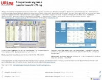 URLog, version 0.1.10, functions as a freeware amateur radio logging application designed for basic QSO record-keeping. The software provides core functionalities for inputting contact details, including callsign, date, time, frequency, and mode, which are fundamental for maintaining an amateur radio logbook. Its design emphasizes ease of use, making it accessible for operators who require straightforward logging capabilities without extensive advanced features. The application's utility lies in its simplicity for everyday logging tasks, particularly for those who prefer a local software solution over web-based loggers. While specific data formats supported are not detailed, standard logging practices suggest ADIF compatibility for export, facilitating integration with other ham radio software or online logbooks. The software's compact download size of approximately 4.5 MB indicates a lean installation, minimizing system resource usage.
 -
 Operating on 160 meters from a city lot is always a challenge. Here's how K9YC does it.
 -
 The G5RV multiband HF antenna, designed by Louis Varney (G5RV) in 1946, is a popular compromise antenna offering good overall performance on most HF bands when paired with an external antenna tuner. The basic full-size G5RV measures 102 feet across the top for 80 through 10 meter operation and is fed at the center via a 34-foot low-loss feed-stub. This interaction between the radiating section and the feed-stub facilitates matching across 80-10 meters with a standard tuner, often eliminating the need for ladder line directly to the shack. The antenna's design center frequency is 14.150 MHz, configured as a 3/2-wave dipole on 20 meters, with its 102-foot length derived from long-wire antenna formulas. Construction details emphasize the matching section, which can be open wire, ladder line (window-type), or TV twin lead. Each type has a specific velocity factor (VF) affecting its physical length for an electrical half-wave on 14 MHz; for instance, open wire requires 33.7 feet (VF 0.97), ladder line 31.3 feet (VF 0.90), and TV twin lead 28.5 feet (VF 0.82). The article provides formulas for calculating these lengths and discusses the antenna's behavior on individual bands, from 3.5 MHz where it acts as a shortened dipole, to 28 MHz where it functions as two three-half-wave long-wire antennas fed in-phase. Practical construction notes include recommendations for vertical descent of the matching section, sealing the coax junction, providing strain relief, and winding a coaxial choke coil to mitigate common mode current. The resource also presents dimensions for double-size (204 ft) and half-size (51 ft) G5RV versions, along with their corresponding matching section lengths for various line types, making it a versatile reference for hams considering this classic wire antenna.
 -
 Garmin Kenwood Icom Vertex Alinco and more
 -
 Operating in the Nordic region often requires specific call sign lookup tools, and this resource offers a dedicated search service for Swedish amateur radio operators. Users can query the database by entering a call sign, a family name, or a city, facilitating the identification of hams within Sweden. This functionality is particularly useful for DXers attempting to confirm contacts or for local hams seeking to connect with others in their area, leveraging the official data provided by the Swedish Amateur Radio Society (_SSA_). Such a lookup service streamlines the process of verifying contacts for awards like _DXCC_ or for general QSLing purposes. While many global callbooks exist, a national service like this often provides more granular and up-to-date information for its specific region. The ability to search by city can be especially beneficial for local rag-chewing or for coordinating activities within a specific geographic area, offering a practical complement to broader international databases.
 -
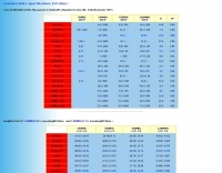
 The Resonant Feedline Dipole (RFD) HF antenna design utilizes a single piece of coaxial cable and a stranded wire section, forming a 1/4-wavelength radiator. This configuration, based on a 1997 ARRL Handbook design (page 20.17), functions by RF traveling on the inside of the coax shield and returning on the outside, creating the second half of the dipole. A choke wound into the feedline prevents RF current from flowing back down the feedline. Construction details include using RG-58a/u coax for a 75m version, with a 1/4-wavelength section of stranded wire soldered to the center conductor. The document provides choke dimensions for RG-213, RG-8, and RG-58 coax across 3.5 MHz to 28 MHz, specifying cable length and number of turns. Dipole dimensions are also tabulated for frequencies from 3.6 MHz to 28.4 MHz, listing overall length and individual leg lengths. Field tests included deployment near Bryson City at 5 feet off the ground and as a sloper during WCARS Field Day in Asheville, yielding successful local and regional contacts.