Search results
Query: diagrams
Links: 68 | Categories: 5
-
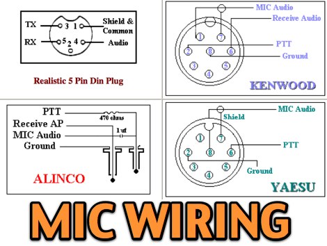 11 most popular MIC wiring diagrams including AZDEN Alinco Icom Kenwood Yaesu Astatic Cobra Sadelta Turner microphens diagrams and pin-end views
 -
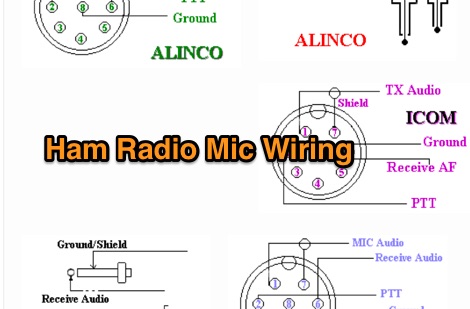 Kenwood Alinco and Icom amateur radio transceivers - Mic Wiring diagrams by pictures
 -
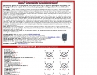 Microphone wiring can be a pain if your not sure how to work out which wire goes where
 -
 Circuit diagrams, CB and HAM mods, alignments, data sheets and pinouts, a massive site with over 600 pages of free info
 -
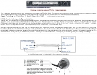
 SSTV freeware software for Windows by Mako JE3HHT. MMSTV is a free software application designed for transmitting and receiving SSTV (Slow Scan Television) images over HF bands. It allows radio amateurs to share still pictures using sound-card interfaces and a transceiver. The program supports popular SSTV modes (Martin, Scottie, Robot, etc.), real-time RX/TX monitoring, and easy image editing. Its user-friendly interface and reliability make MMSTV a favorite choice among ham operators worldwide. Ideal for showcasing QSL cards, shack photos, or technical diagrams over the ai An excellent SSTV program that requires only a computer with soundcard, no expensive TNC required. Works on all Windows version including Windows XP, Vista and Windows 7.
 -
 Demonstrates the construction of **magnetic loop antennas**, detailing both multi-turn and single-turn designs. It covers a 30-inch diameter multi-turn loop for 80 meters, based on a February 1996 QST article, and an octagon single-turn loop made from 15mm copper tube with a 4.8-meter circumference, operating from 7 MHz to 14 MHz. The document also presents a smaller 800mm diameter loop for 14 MHz to 28 MHz, emphasizing the importance of high-voltage tuning capacitors. Covers the design and construction of custom **butterfly capacitors** and piston capacitors, including a split stator capacitor with 140 pF capacitance and a 6000 Volt rating, and a butterfly capacitor with 5-65 pF and 7200 Volt rating. It explains why butterfly capacitors are preferred over split stator types for high power applications due to lower losses and direct series connection of rotors, reducing resistive losses from wiper contacts. Material recommendations include clear PVC for plates and brass or stainless steel for non-magnetic hardware. Addresses practical considerations such as feeding the loop with a shielded 1/5 Faraday loop made from RG213 or RG8 coax, achieving VSWR 1.1 across bands, and optimizing its placement 180° from the capacitor. It also discusses mechanical joint resistance, dissimilar metal oxidation prevention using Vaseline, and a simple method for determining radiation angle with a TL-light tube. The guide includes diagrams for rotor, stator, and end plate construction.
 -
 Alan Cobra Uniden President Galaxy and more microphone wiring diagrams
 -
 Galaxy web site updates and additions with modifications, diagrams, and schematics for galaxy radios
 -
 A well documented plan to build a magnetic loop antenna for Shortwave Listening, includes photos and diagrams.
 -
 Specializes in antique radio schematics, circuit diagrams and service data for vintage tube radios. Carries information for American, Canadian and European antique radios.
 -
 Show diagrams, winding methods and tables of some 1:1 and 4:1 baluns for 1.8 - 30 MHz suitable for use up to 200W (400W peak) on systems using 50 or 75 ohm coaxial cable input where SWR should not exceed 1.6:1.
 -
 Service information, modifications, diagrams, manuals and schematics, and technical files on Galaxy DX Radios.
 -
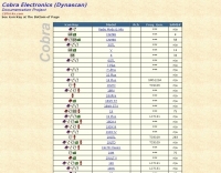 Service information, manuals, diagrams pictures and schematics, and technical files on Cobra Radios
 -
 Retrospective of a mark now disappeared. Jumbo, Multimode, Concorde, Puma, Viking. Photographs, diagrams, adjustments etc.
 -
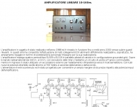 Italian page including pictures schematics diagrams of an home made linear amplifier using four EL509 in parallel. Output power is about 700W.
 -
 Constructing a high-power solid-state amplifier for HF operations presents unique challenges, particularly when aiming for significant output like 600 watts. This project details an amplifier design employing **Motorola MRF150** FETs, a common choice for their robust performance in RF power applications. The design emphasizes achieving substantial power output, a critical factor for effective DXing and contesting, where every decibel can make a difference in signal propagation and readability. While specific circuit diagrams or construction details are not directly presented on the current page, the mention of MRF150 FETs points towards a design that would typically involve push-pull configurations, impedance matching networks, and robust power supply considerations to handle the high current demands. Such amplifiers are often built with an eye towards linearity and efficiency across the HF bands. Amateurs pursuing similar high-power solid-state projects often share insights on thermal management, intermodulation distortion, and component sourcing, all vital for a stable and reliable amplifier capable of delivering 600 watts into a proper antenna system.
 -
-
 The document details the optimization and construction of the _Maria Maluca_ antenna, a compact 6-band (20m-6m) directional beam. It presents a comparative analysis of shortwave antenna principles, highlighting the efficiency gains achieved by using an open feeder line and tuner as a resonant unit, contrasting this with the losses associated with traps or capacitive loads in multiband antennas. The resource specifically revisits an older South American 2-element design for 10, 15, and 20 meters, applying modern NEC-based software to develop a six-band version. Performance data is meticulously tabulated, showing impedance, free space gain, gain at 12m height, elevation angle, and front-to-back (F/B) ratio for each band from 20m through 6m. For instance, on 15m, the antenna achieves 5.1 dBd free space gain and 13.72 dB F/B ratio. The construction section provides practical guidance on element assembly using aluminum pipes and hose clamps, detailing the use of a heavy-duty glass fiber reinforced polyamide rod for electrical separation and bending strength. It also specifies the use of 450-ohm _Wireman_ line CQ 552 for the transmission line. The document includes diagrams for rod fixing, an air-wound balun, and a vertical elevation diagram for the 15m band, illustrating its DX qualification. It also discusses the antenna's suitability for portable and expedition operations, noting its compact transport dimensions (max 1.50m length, 12 lb weight) and quick assembly time (under 15 minutes). The author, Dipl.Ing. Helmut Oeller, DC6NY, is identified as a source for material kits.
 -
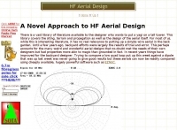 A novel approach to aerial evaluation with diagrams and graphs by G3CWI
 -
 Article about magnetic loops, construction notes and diagrams
 -
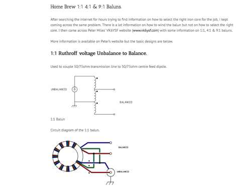 Circuit diagrams to homebrew different baluns by vk2awx
 -
 Specializes in antique radio schematics and capacitors. carries antique radio schematic diagrams and electronic circuit service information for american, canadian and european antique radios.
 -
 For radio amateurs seeking compact and efficient antenna solutions, particularly for restricted spaces or noise reduction, HF loop antennas present a viable option. This resource compiles several articles from the ARRL, detailing the theory, design considerations, and practical construction of various loop configurations. Topics include small transmitting loops, receiving loops, and multi-band designs, often emphasizing their performance characteristics such as directivity, bandwidth, and impedance matching. The collected articles provide insights into the comparative performance of different loop geometries, such as circular versus square loops, and discuss the impact of conductor size and tuning methods on efficiency. Practical applications are explored, including their use in portable operations, stealth installations, and urban environments where noise mitigation is critical. The content often includes construction diagrams, parts lists, and performance data derived from modeling or field tests, enabling hams to replicate or adapt the designs for their specific operating conditions.
 -
 This resource, "Transistor Audio Preamplifier Circuits," offers comprehensive design guidelines for constructing **bipolar transistor** audio preamplifiers. It delves into critical aspects such as quiescent current setting, voltage gain calculation, and the impact of various component choices on circuit performance. The content provides several _schematic diagrams_ illustrating different preamplifier configurations, including single-stage common emitter and two-stage designs, alongside explanations of their operational characteristics and practical implementation considerations. The analysis extends to frequency response, noise performance, and distortion, providing insights into optimizing these parameters for specific audio applications. The resource presents calculated gain figures for various stages, demonstrating how to achieve desired amplification levels. It also discusses the importance of proper power supply decoupling and input/output impedance matching, crucial for integrating these preamplifiers into larger audio systems or ham radio transceivers. The practical application of these designs is evident in their suitability for microphone preamplifiers or general-purpose audio amplification.
 -
 Circuit diagrams drake tr7, Schaltbilder Drake Tr7, antenna tuners, baluns, and home brew power supplies, dual tone ssb test generator, zweiton ssb test generator, zweiton testgenerator, dual tone test generator by DK4DDS
 -
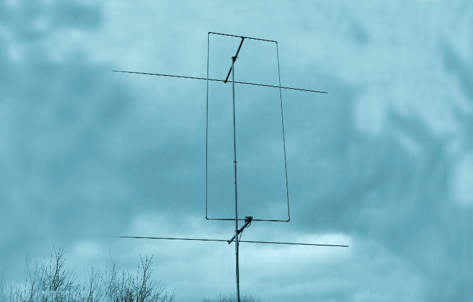 The Quadlong antenna for the six meter band. This antenna feature a total gain of 6,4 dBd, F/B 21 dB and is also available in 70MHz version. Includes detailed pictures and plot diagrams.
 -

-
 This is a "techie" site, dedicated to presenting service manuals, parts lists, schematic diagrams and other information of value to restorers and technicians who try to keep these radios working
 -
 Color photos, schematic and diagrams for an article written by N2APB for Fall 2000 QRPp. Also the subject of a presentation made at the Pacificon QRP Forum in October 2000.An Integrated and Portable PSK Station for 80 & 20 without using a PC!
 -
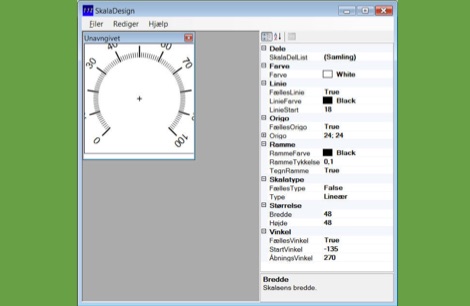 A danish only scale diagrams designer, usefull to draw front panels and dial scale knobs, windows freeware.
 -
 This document details the design and construction of the PA70H, a 50-watt RF amplifier for the 70MHz (4-meter) amateur radio band. Built around the Mitsubishi RD70HVF1 MOSFET transistor, the amplifier delivers 45-55W output with 3-5W input power while operating on 13.8V DC at approximately 7-8A. The PCB design incorporates multiple protection circuits including overcurrent, SWR, and temperature control. The amplifier features various control modes including GND PTT, +13.8V PTT, and RF VOX. Two versions are available: PA70HLI (requiring 100mW input with additional driver) and PA70H (for 3-5W input). The comprehensive documentation includes circuit diagrams, assembly instructions, and performance data showing successful operation from both 100mW and 3.5W input sources.
 -
 Examines the historical role of telegraphy within Canadian railway operations, detailing the evolution of communication systems crucial for train dispatch and coordination. It covers the technical substance of railway telegraphy, including equipment, operational procedures, and the personnel involved, such as agents and operators. The resource provides insights into the **F59PH locomotive** history, development, and components, alongside diagrams of various parts like antennae and traction motors. The content also explores the practical application of these systems by documenting specific railway events, such as the CPR Galt Sub operations from 1895-1971 and GO Transit's operational history. It includes photo galleries, schematics, and diagrams of locomotives and cab cars, offering a visual and technical comparison of different railway equipment. The site also features information on **GO Transit** rolling stock, including MP40s and commuter coaches, providing a historical context for railway communication and transportation.
 -
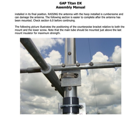 This manual is an edited version of the GAP supplied document, complete with diagrams, pictures and assembling notes by Mitch Baum AE2A. This is 29 pages document in PDF Format.
 -
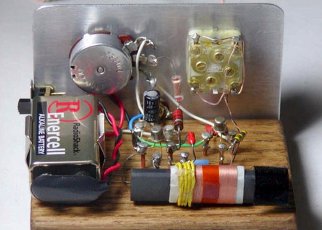 Collection of several Crystal Radio receiver circuits with schematics diagrams and pictures
 -
 The page provides detailed instructions on how to build a 60 meter End Fed Half Wave Antenna Tuner, with large pictures and diagrams. It is aimed at amateur radio operators looking to construct their own antennas for the 60 meter band.
 -
 Kenwood schematics diagrams in high resolution format, includes Kenwood TS-830S , TS-820S and TS-520S
 -
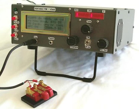 Integrated PSK station for 80 & 20 meters without using a PC Pictures and diagrams by N2APB
 -
 An introduction to RF mixes and their main characteristics, article with diagrams and illustrations by VA3IUL
 -
 The WB5RVZ Genesis Radio G40 build log documents the construction of a 5W QRP 40m SDR transceiver kit, detailing each phase of assembly from power supply to RF filtering. It provides specific component lists, parts placement diagrams, and testing procedures for stages like the local oscillator, Tayloe detector, and RX op-amps. The resource highlights discrepancies between documentation versions and offers practical advice for builders, including a "virtual build" approach to preemptively address potential ambiguities in component identification and placement. It also addresses a specific "VK6IC Fix" for early board revisions, involving trace cuts and jumper wires for improved performance. The build log presents measured voltages and expected current consumption for various stages, such as the 4.9-5.0 Vdc on the 5V rail and under 100mA for RX current. It outlines critical adjustments like image rejection tuning, a common procedure for direct conversion receivers. The resource also includes practical tips for handling components like the 2N3866 transistor and its heatsink, emphasizing pre-assembly. It details the winding of two 1.45 uH toroidal inductors on T50-6 cores with 17 turns of #20 AWG wire, crucial for the RF path.
 -
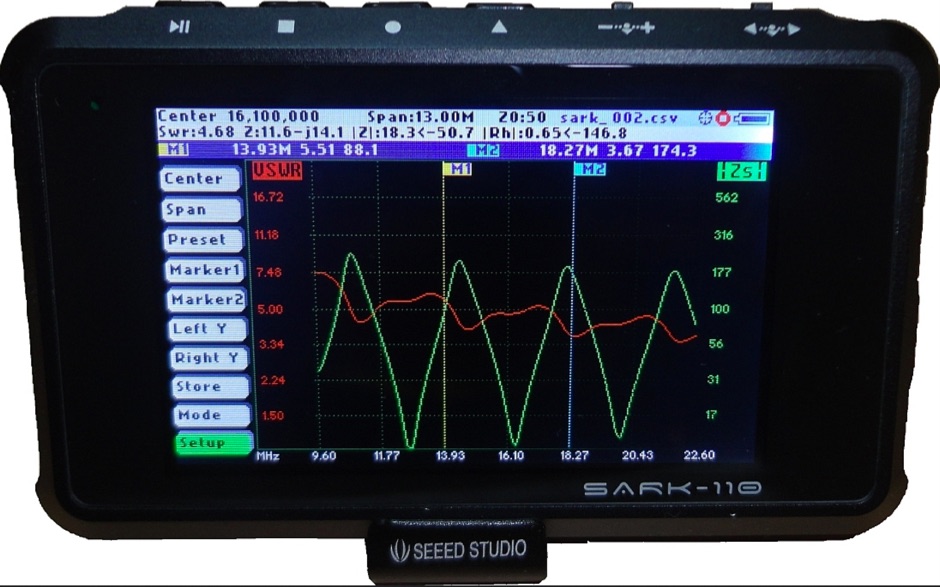 The SARK-110 is a completely new design concept for an Antenna Analyzer. This is a truly pocket size device, so you can take it anywhere. It offers a gorgeous 3" high-resolution, active-matrix color display that allows information-rich diagrams, works from 0.1 to 230MHz
 -
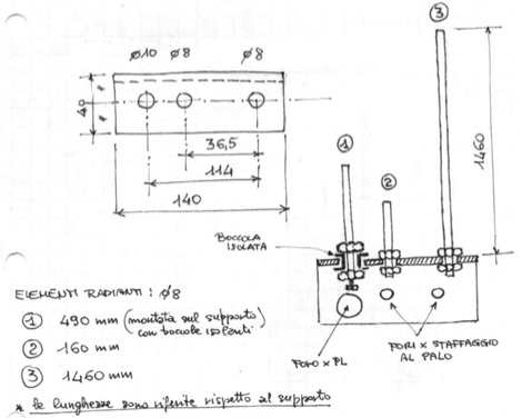 A multiband J-Pole antenna project that cover 144,220 and 430 MHz. The articles includes several pictures of this multi-band antenna, including handmade schematics and diagrams, project is mainly in Italian
 -
 DTMF Keypad for radios without one. A project with picture and schematic diagrams to homemade a DTMF keppad
 -
 Presents the full owner's manual for the _Drake R-4C_ communications receiver, specifically a late version edition. This resource outlines the comprehensive operational instructions, covering everything from initial setup and tuning to advanced features and controls. Hams can reference detailed diagrams and explanations for proper signal reception across various amateur bands. The manual includes critical information for alignment procedures, ensuring the receiver performs to its optimal specifications. It details the steps required for calibrating the internal circuitry, which is essential for maintaining sensitivity and selectivity over time. My experience with vintage Drake gear confirms the value of these original documents for accurate adjustments. Furthermore, the document provides insights into troubleshooting common issues and performing routine maintenance. It serves as an authoritative guide for anyone operating or servicing this classic piece of amateur radio equipment, helping to preserve its functionality for years of DXing and ragchewing.
 -
 This DIY vertical multi-band Windom antenna offers a practical and effective solution for amateur radio enthusiasts seeking a versatile and compact antenna for HF communications. Its simplicity of construction, multi-band capability, and favorable performance make it a valuable addition to any radio shack. The article provides detailed instructions on constructing the antenna and balun, along with diagrams and component specifications. Field tests demonstrated successful contacts with stations across Europe and North America on 14, 18, and 28 MHz. The antenna exhibited comparable performance to a W3DZZ dipole and outperformed a Cobweb antenna on 18 MHz. Low noise levels were observed, effectively suppressing background noise.
 -
 Station QRP presents various **circuit diagrams** for constructing low-power AM vacuum tube shortwave transmitters, catering to enthusiasts interested in vintage radio technology. The resource details schematics ranging from simple to more complex designs, enabling hams to build their own QRP AM transmitters for operation on frequencies like 6.925 kHz AM. It emphasizes the use of vacuum tubes, providing a technical foundation for understanding and replicating classic shortwave broadcasting methods. The content is geared towards those who enjoy the hands-on aspect of electronics and the unique characteristics of tube-based RF circuits. Building these transmitters allows operators to experience the nostalgia of early shortwave radio, with the site specifically mentioning a pioneer station on 6.925 kHz AM. The designs facilitate experimentation with low-power AM transmission, offering practical application for homebrew projects. The focus on QRP (low power) operation aligns with a segment of the amateur radio community that values efficiency and minimalist setups, providing a distinct alternative to modern solid-state transceivers.
 -
 The Buddistick antenna, as demonstrated by KP4MD, effectively handles up to **250 watts** and provides coverage from 40 through 10 meters, with an optional coil extending operation to 80 and 60 meters. KP4MD's video presentation meticulously describes the antenna setup, emphasizing the critical role of the _shunting coil_ for achieving resonance on lower bands like 40 and 80 meters. This practical approach highlights how a compact antenna can deliver solid performance from a constrained location. SWR curve diagrams are included, clearly illustrating the impact of the shunting coil on the antenna's resonating frequency. These visual aids provide concrete evidence of the adjustments needed for optimal operation across different bands, particularly when space is at a premium. KP4MD's insights are particularly valuable for hams operating from apartments or other limited spaces, showcasing real-world results from a balcony installation.
 -
 This article presents a comprehensive guide to constructing a multiband vertical wire antenna. The design features parallel wires for various bands, all connected to a single balun, ensuring ease of assembly and adjustment. Materials required include a fishing rod, PVC tubing, and inexpensive wire. The antenna is lightweight, cost-effective, and suitable for field use or as an additional home setup. Detailed instructions and diagrams are provided to facilitate successful construction and optimal performance across multiple frequencies.
 -
 This PDF guide provides detailed instructions and diagrams for constructing a fan dipole antenna, a popular choice among hams for multiband operations. The guide covers the design, materials needed, and installation process, offering step-by-step guidance to help hams set up an effective antenna system for their radio operations.
 -
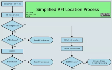 I have RFI, now what– Locating it. This article is the first of a three parts article, that covers the problem of locating the RFI source. Author make use of an SDR receiver to locate RFI emissions. Ai interesting RFI location process diagrams helps on following the various phases, permitting the discovery of almost 75% of the RFI issues.
 -
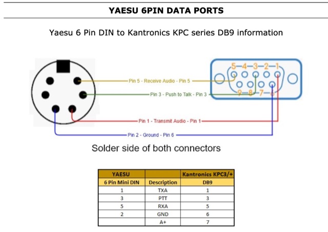 Kantronics Pinouts with information on Icom, Kenwood Motorola, Yaesu and Vertex radio connections.