Search results
Query: elf receiver
Links: 9 | Categories: 0
-
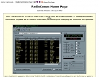 Demonstrates RadioComm, a freeware Icom transceiver/receiver controller program for Windows, which facilitates memory programming, spectrum analysis, and interfacing with extensive frequency databases. The software allows users to program their Icom radio's memory, generate radio-frequency spectra, and connect the radio to a computer-based frequency database. It supports various Icom models, offering bidirectional control where virtual controls mirror the transceiver's physical controls and vice versa. The program's spectrum analysis feature, exemplified by tuning the WWV time standard at 15 MHz, provides insights into the AM passband, a capability often found in high-end Icom transceivers. While RadioComm offers these functionalities, the author, Paul Lutus, notes that it has been superseded by JRX (a virtual radio) and IcomProgrammer II (a memory programming utility), which are described as superior and compatible with more platforms. RadioComm is available as a 516 KB self-extracting executable, requiring an Icom CT-17 RS-232 interface box for radios that need it. Users can also customize the plain-text database to include unsupported Icom models. However, the author explicitly states that no user support is provided for this free program.
 -
 Constructing a Lindenblad antenna for 137MHz NOAA satellite reception involves specific design considerations for optimal performance. The resource details the use of 4mm galvanised steel fencing wire, 300-ohm television ribbon cable, and wood/plastic components for the antenna structure. Key dimensions for a 137.58MHz-resonant antenna are provided, derived from the ARRL Satellite Handbook, specifying s, l, w, and d as 42, 926, 893, and 654mm respectively. The antenna is designed for Right Hand Circularly Polarised (RHCP) signals, requiring the four folded dipole elements to be tilted clockwise by 30 degrees. A significant aspect covered is impedance matching between the antenna's 75-ohm impedance and a typical 50-ohm receiver input. A twelfth-wave matching transformer, constructed from 117mm sections of 50-ohm RG-58 and 75-ohm RG-59 coax with a 0.66 velocity factor, is described. The article also addresses coaxial cable and connector selection, recommending 75-ohm Type-N connectors for RG-6 cable in professional setups and F56/F59 connectors for general use, while strongly advising against PL-259/SO-259 connectors for VHF. Strategies for mitigating Radio Frequency Interference (RFI) are discussed, including antenna placement to shield from local TV transmitters and the use of commercial or DIY band-pass filters, such as cavity resonators or helical notch filters, along with ferrite chokes on coaxial cables. Antenna orientation is explored, noting the Lindenblad's 'cone of silence' directly overhead and its maximized sensitivity towards the horizon. An experimental vertical tilt of 90 degrees is presented as a method to improve overhead reception and reduce interference from strong horizontal signals, particularly relevant in high RFI environments like the Siding Spring Observatory site.
 -
 Examines the historical landscape of "boat anchor" amateur radio equipment manufacturers, focusing on the technical innovations and market dynamics that shaped the industry from the pre-WWII era through the transition to SSB. It details the origins and key product lines of prominent U.S. companies like _Collins Radio Company_, _Central Electronics_, and _Barker & Williamson_, highlighting their contributions to receiver and transmitter design. The resource contrasts early AM technology with the advent of SSB, explaining the circuit changes required in receivers and the complete rethinking needed for transmitters. It discusses the impact of military contracts on company survival and the eventual shift towards smaller, self-contained transceivers. Specific examples, such as the _Collins R-390/URR_ receiver and the _Central Electronics 100V/200V_ broadband transmitters, illustrate the engineering prowess and design philosophies of the era, offering insights into their operational characteristics and enduring appeal among collectors.
 -
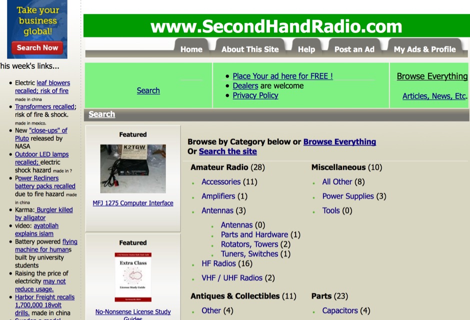 SecondHandRadio.com provides a platform for the amateur radio community to buy, sell, and swap used, surplus, and obsolete electronics and electrical equipment. The site facilitates transactions for a wide range of items, including ham radio transceivers, test equipment, shortwave receivers, antennas, and vintage radio components like tubes. Users can place classified advertisements with photos at no cost, catering to individuals, radio clubs, and commercial dealers seeking to liquidate or acquire gear. The platform emphasizes ease of use with a straightforward sign-up process and no associated fees or commissions for listing or selling items. It positions itself as a primary resource for used electronics within the USA, fostering a direct connection between sellers and buyers without intermediary charges. The service supports various categories beyond amateur radio, extending to military radios and antique equipment, thus serving a broad spectrum of radio enthusiasts and collectors.
 -
 Operating on the 2200m band (135.7-137.8 kHz) often presents challenges for amateur radio transceivers, which typically exhibit poor receiver performance at these very low frequencies. This project addresses the issue by providing a design for a dedicated 137 kHz antenna preamplifier, specifically tailored to improve signal reception for radios such as the _Yaesu FT-817_. The preamplifier circuit utilizes a low-noise FET input stage, crucial for minimizing self-generated noise and maximizing the signal-to-noise ratio from weak LF signals. The design includes a detailed schematic, component values, and construction notes, enabling homebrewers to build a functional unit. The goal is to achieve significant gain, making the faint signals on 2200m more discernible and improving overall band usability. Key design considerations include impedance matching to typical antenna systems and ensuring stable operation across the narrow LF segment. The circuit aims for a **low noise figure** and sufficient amplification to overcome the inherent limitations of general-purpose HF transceivers when operating below **200 kHz**.
 -
 Over two decades ago, the Kenwood TS-850S HF transceiver established itself as a robust performer, known for its excellent receiver and versatile operating features. This vintage rig, often found on the used market, continues to be a favorite among many amateur radio operators for its solid construction and reliable performance across the HF bands. Adrian's Yahoo! Group provided a dedicated forum for TS-850S owners to exchange insights, troubleshoot issues, and share modifications or operational tips. Such community-driven platforms were crucial for extending the operational life and maximizing the utility of classic transceivers, fostering a spirit of mutual aid among hams. Discussions frequently covered topics like DSP unit upgrades, common repair challenges, and optimizing the rig for contesting or DXing, reflecting the enduring interest in this particular Kenwood model.
 -
 A cavity filter, often a critical component in _duplexer_ designs, functions as a sharply tuned resonant circuit, allowing only specific frequencies to pass while attenuating others. These filters are essential for maintaining signal integrity in environments where multiple transmitters and receivers operate simultaneously on closely spaced frequencies, such as in repeater stations. The article details how these filters, sometimes referred to as _notch filters_, achieve high Q factors, which are crucial for their performance. Understanding the principles of cavity filters is fundamental for any amateur radio operator involved in repeater operation or designing custom RF front-ends. The discussion covers the basic circuitry and operational characteristics that enable these devices to provide significant isolation, often achieving **-80 dB** or more between transmit and receive paths. This level of isolation is vital for preventing receiver desensitization and intermodulation distortion. Properly tuned cavity filters ensure that a repeater can transmit and receive simultaneously on different frequencies without self-interference, a common challenge in VHF/UHF operations.
 -
 Presented is a historical collection of short-wave listening (SWL) QSL cards, primarily from the late 1930s and early 1940s, offering a glimpse into early international broadcasting and the technical pursuits of SWL operators like Les Miles during that era. The resource showcases specific QSLs from stations such as _Broadcasting Corporation of Japan_, _XGOY - The Central Broadcasting Administration_ in Chungking, China, and _Australian broadcasting ship, Kanimbla VK9MI_, each with reception dates and frequencies like 11.90MHz or 9.525MHz. It highlights the self-sufficiency of SWL enthusiasts who constructed and maintained their own radio and test equipment, evoking the sensory experience of vintage valve receivers. The collection provides concrete examples of international broadcast stations active before and during World War II, including _2RO3 - Rome_ and _WRUL - World Wide Broadcasting Foundation_ from Boston. Each QSL entry details the station, location, reception date, and often the frequency, such as 9.63MHz or 11.26MHz, allowing for historical verification of broadcast schedules. The resource also briefly mentions the operational details of the _VK9MI_ offshore radio station, directing readers to further information on its history. This compilation serves as a tangible record of global radio communication during a pivotal historical period.
 -
 KISS703 is a 703 Hz narrowband digital mode for amateur radio, designed for simple, low-power operation without computers. A 500 Hz pilot tone ensures frequency alignment, replaced by unique tones for 37 symbols (letters, numbers, space). Built from common discrete components, it draws about 40 mA at 12 V, ideal for SOTA/IOTA use. The receiver uses amplification, wave shaping, and a pulse-counting frequency meter for manual decoding via a calibrated meter. Transmitter and receiver calibration involves marking meter positions for each tone, enabling fully self-contained messaging with minimal hardware in portable or fixed operations.