Search results
Query: eve mount
Links: 53 | Categories: 0
-
 Dissects the internal components of the popular _Antron 99_ vertical antenna, revealing its unique design elements. The analysis details the construction of the coaxial phasing sections, which contribute to its multi-band performance across 10, 12, 15, and 17 meters. Observations include the use of fiberglass tubing for weather protection and the specific arrangement of conductors within the antenna's structure. The examination highlights the antenna's reliance on a series of coaxial stubs to achieve resonance on multiple HF bands without external tuning. This internal architecture provides insights into how the _Antron 99_ manages impedance matching and radiation patterns for effective DX operation. Further details cover the antenna's base mounting and overall physical dimensions.
 -
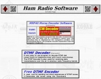 MRP40, a successor to the well-regarded MRP37, offers robust Morse code decoding capabilities by processing analog audio signals via a sound card and displaying the decoded text on a computer monitor. My own field tests with similar sound card decoders confirm that the quality of the audio input and proper signal conditioning are paramount for achieving reliable decoding, especially with _weak signals_. The program also facilitates CW transmission, converting keyboard input into Morse code to key a transceiver, a feature I've found useful for practicing sending or for quick contest exchanges. Beyond its core CW functions, MRP40 incorporates a convenient mini-logbook, which automatically checks for prior contacts and allows for quick logging by double-clicking callsigns in the receive window. This integration streamlines the logging process, a significant advantage during busy operating sessions where every second counts. The software also generates Morse tones using the sound card, a handy utility for testing tone sequences or for basic code practice. Additionally, the suite includes a DTMF decoder and generator, which can be used for decoding telephone dial tones or data transmissions over amateur radio frequencies. It also features MF-TeleType, a sound card-based audio data modem for transmitting text via radio, utilizing a principle similar to DTMF for encoding and decoding, offering a simple method for digital text communication.
 -
 "Some have called the T2FD a ""squashed rhombic"" antenna. It does bear some design similarities to the non resonant rhombic, but theoretically it is admittedly inferior. However, the T2FD performs well in a modest amount of space."
 -
 Presents a practical design for a **crossed-dipole turnstile antenna** specifically engineered for 2-meter Amateur Radio Direction Finding (ARDF) events. The author, WB6RDV, details a robust, omnidirectional, horizontally-polarized antenna, addressing the international ARDF rules requiring such characteristics at a height of two to three meters above ground. This contrasts with the vertical polarization often used in Southern California, highlighting the design's adherence to specific event requirements. The electrical design employs a classic crossed-dipole with a 75-ohm phasing section, resulting in a slight impedance mismatch and an SWR of approximately 1.3:1 with a 50-ohm feedline. Construction utilizes readily available and inexpensive PVC plumbing components and 1/8-inch bronze welding rod for elements. The guide provides step-by-step instructions for mechanical assembly, including drilling element holes at precise 90-degree spacing and preparing the RG-179 matching section. WB6RDV shares insights from his own build experience, discussing the use of plated brass versus aluminum spacers for element attachment and the effectiveness of crimping as an alternative to soldering. The document also covers final assembly, including the integration of ferrite beads as a choke balun and options for weatherproofing and alternative mounting configurations, emphasizing the adaptability of the design for other VHF bands through scaling.
 -
 Presents the KE4UYP linear-loaded vertical antenna design, which introduces very little loss on 80 or 160 meters, achieving an overall radiation efficiency of 80% to 85%. This design addresses common pitfalls of traditional base-fed verticals by placing the majority of the current at the top of the antenna, eliminating the heavy reliance on extensive ground radial systems. The author's initial 10-meter model, only three feet tall, yielded 5/9 signal reports to Anchorage, AK, and Europe, confirming its effectiveness. The antenna incorporates both vertically and horizontally polarized radiators, with a 1/4 wavelength horizontal counterpoise located at the feed-point, near the top, to create an almost totally omnidirectional pattern with high wave angle horizontally polarized radiation. This dual polarization ensures even illumination across all take-off angles, making it effective for both local contacts and **DXing**. The vertical element is linear loaded, adding capacitance reactance and making it longer than the horizontal element to achieve resonance and raise the feed-point impedance to 50 ohms. Fine-tuning the antenna requires careful adjustment, as tower reactance can vary. The article suggests starting with 80 feet for 80m and 170 feet for 160m for the vertical wire, then trimming for resonance. Bandwidth specifications include 300 kHz under 2:1 **SWR** on 80m and 100 kHz on 160m when suspended between trees, or 150 kHz on 80m when side-mounted on a tower.
 -
 The 80-meter loop antenna, measuring 86 meters (282 feet) of wire, effectively operates across 8 HF bands from 80 through 10 meters, despite its length being a compromise for specific bands. This design prioritizes a "low enough" SWR across multiple bands, aiming for lower SWR values on higher frequencies due to increased feedline losses. A 200-ohm feedpoint impedance provides a workable SWR on every band, with feedpoint impedances ranging from 100 ohms for lower bands to 300 ohms for higher bands. Radiation patterns for the 80-meter loop, mounted at 15 meters high, show a maximum gain of 7.6 dBi at a 90-degree takeoff angle on 80 meters, and up to 12.9 dBi at a 10-degree takeoff angle on 12 meters. This configuration supports regional contacts on 80 meters and provides good DX performance on higher bands. Practical construction notes emphasize using robust supports like trees, ensuring wire slack with _egg insulators_ for wind resilience, and employing an oversized 2 kW 4:1 _balun_ to safely handle higher SWR conditions, even with 100W transceivers. Feedline losses are minimized using _LMR-400_ coax or ladder line, with power transfer efficiency between 80% and 95%. Antenna simulations were performed using _xnec2c_, and the provided NEC file is compatible with other NEC2 derivatives. The antenna is tunable on 6 of 8 bands with an internal ATU and all 8 bands with an external autotuner like the LDG AT-200 Pro.
 -
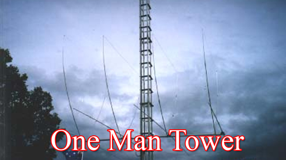 Complete tower system incorporates rotator mount, and lateral support collars. You never have to climb again - and forget the hassle of tilting over to work on large arrays. The "One Man Tower" is the strongest dmall footprint free standing self erecting tower in the world
 -
 Interesting article on mobile antennas by Cebik. . The article offers advice for setting up and operating mobile antennas for ham radio use. It emphasizes the lossy nature of mobile-in-motion antennas but encourages users to rise to the challenge. Steps include safeguarding car electronics, choosing proper cabling, and carefully selecting and mounting antennas. It highlights potential issues like roof mounting, trunk lip grounding, and side-mounting for trucks. For stationary operation, options like dipoles or beams are explored, with safety tips for masts and guying systems. Lastly, it stresses safety, suggesting stopping the vehicle to operate whenever possible
 -
 Presents G0GSF Brian's ZS6BKW antenna, a refined iteration of the classic G5RV, offering improved performance across multiple HF bands. The design emphasizes specific radiator and ladder line lengths to achieve lower SWR on 40m, 20m, 17m, 12m, and 10m, making it a practical choice for operators seeking a single wire antenna solution. The document includes critical dimensions for the flat-top and the 450-ohm ladder line section, which are key to its multiband resonance characteristics. Unlike the original G5RV, the ZS6BKW aims for direct 50-ohm feedpoint impedance on several bands, reducing the need for an external antenna tuner. My field experience with similar optimized dipoles confirms that precise construction, particularly the ladder line length, is paramount for realizing the intended SWR benefits. This design offers a compelling alternative for hams with limited space or those preferring a less complex antenna system.
 -
 Vortex Antenna Systems, radio communication antenna aanufacturer and supplier of antenna related hardware. Ham radio HF and VHF Antennas, antenna parts, mast and mounts.
 -
 Demonstrates the essential steps for winding **toroidal cores**, a fundamental skill for amateur radio operators engaged in homebrewing and kit building. It addresses the critical aspects of selecting the correct core material and wire gauge, emphasizing the importance of precise turn counting and consistent winding tension to ensure optimal circuit performance. The resource details methods for preparing the wire, including techniques for safely removing enamel insulation from leads using flame, sandpaper, or a solder pot, and provides guidance on tinning the exposed wire. Explains the process of mounting the wound toroid onto a printed circuit board, highlighting the need for careful lead placement and secure soldering to prevent shorts and ensure mechanical stability. It also offers a practical formula for calculating the required wire length based on the desired number of turns and the specific **toroid** size, referencing common core types like T-50 and FT-240. The guide stresses the importance of verifying the inductance of the wound component, often using an inductance meter, to confirm it matches design specifications. Provides practical tips for handling multi-filar windings and managing short lead lengths, which can be particularly challenging. It underscores the necessity of meticulous attention to detail throughout the winding and installation process to achieve reliable and efficient RF circuits.
 -
 Demonstrates the construction of two distinct wideband RF preamplifiers, detailing their component requirements and performance characteristics. The first design leverages monolithic microwave integrated circuits (MMICs) such as the MAR-6, MAR-8, or PGA103, offering a broad frequency response from DC to 2 GHz with a gain of 22.5 dB at 100 MHz and a noise figure typically below 3 dB. This MMIC-based amplifier incorporates protection against power supply transients and features a 50 Ohm input/output impedance, operating from an 8-20 volt supply with low current drain. The second preamplifier design utilizes a BSX-20 transistor, providing amplification across the 14 MHz to 550 MHz range. This simpler, more economical build achieves an average gain of 12 dB at 145 MHz and a noise figure of approximately 1.1 dB. It operates from a 7-15 volt battery supply with a current draw of 6 mA. Both projects emphasize critical construction techniques, such as maintaining short RF connections, ensuring 50 Ohm impedance paths, and mounting the circuit within a shielded enclosure to optimize performance and minimize noise. The resource also discusses phantom power options for antenna-mounted preamplifiers and precautions for use with transceivers, including output protection diodes and static bleeders.
 -
 Demonstrates the design and construction of a 9-element Yagi antenna for the **70 cm band** (432 MHz), based on the DK7ZB concept. The resource details EZNEC+ calculations for a single antenna, providing gain, sidelobe suppression, and front-to-back ratio figures. It also presents a comprehensive analysis of stacking two such antennas, including optimal stacking distance (1000 mm) and the resulting performance enhancements for the stacked array, such as an increased gain of 17.03 dBi. The article includes detailed drawings, wire file dimensions in millimeters, and azimuth/elevation plots for both single and stacked configurations. Practical construction steps are documented with original photographs, illustrating element mounting, the **28 Ohm matching system** using two quarter-wave 75 Ohm transmission lines, and the critical N-connector wiring. It also covers the iterative process of fine-tuning the driven element length to achieve a return loss of 20 dB, validating the EZNEC+ simulation results with actual measurements.
 -
 One specific challenge in the KazShack, operating Single Operator Two Radios (SO2R), involved sharing a K9AY receive antenna between two transceivers without direct RF connection or manual feedline swapping. The solution, detailed in this project, adapts the **W3LPL RX bandpass filter** design to split 160m and 80m signals, feeding them to separate radio inputs while maintaining isolation. This approach also addresses the issue of strong broadcast band interference from a nearby 50KW WPTF transmitter on 680kc. The construction utilizes T-50-3 toroids and NP0 ceramic capacitors, built in a "dead bug" style on copper clad board. Each band's filter coils are identical and resonated to the desired frequency using an MFJ-259 antenna analyzer. A single DPDT relay, controlled by a remote toggle switch mounted on an aluminum panel, facilitates quick band switching between radios, simplifying low-band operations. While some signal loss is noted, the expected lower noise levels from the receive antenna are anticipated to compensate, potentially reducing the need for constant volume adjustments during toggling between transmit and receive antennas.
 -
 Presents a construction project for a linear-loaded 40-meter rotatable dipole, detailing the design evolution from mid-element coils to 300-ohm twinlead loading. It covers material selection, including repurposed fishing poles and EMT conduit, and outlines the assembly process for the antenna elements and mounting plate. The resource provides specific measurements for element lengths and linear loading sections, along with SWR plots demonstrating the antenna's resonance at 7.035 MHz with a 1.1:1 SWR, and bandwidth up to 7.120 MHz below 2:1 SWR. The article documents the antenna's performance during various RTTY and CW contests, including the SARTG RTTY and SCC RTTY contests in August 2006, and the ARRL DX CW and CQWW WPX RTTY contests in February 2007. It reports successful operation at 500-1000W, noting improved performance after replacing a faulty coax cable. Specific DX contacts from British Columbia, including stations in Europe and South Africa, are listed, illustrating the antenna's capability despite its shortened length and relatively low height of 55 feet. The content highlights practical considerations such as weatherproofing the connections and supporting the fiberglass elements to prevent sagging. It also includes a brief comparison to an inverted-V at similar height and a ground-mounted vertical, noting the rotatable dipole's quieter reception. The author shares insights into the iterative design process and tuning adjustments made to achieve optimal resonance.
 -
 A 500-watt mobile antenna project details the conversion of an old 10m hamstick into a highly efficient, multiband "bugstick" for HF operation. The core modification involves replacing the original coil with 25 turns of 6 turns-per-inch, 1.5-inch diameter coil stock, fabricated from #14 wire. This design, intended for a 3-magnet mount on a vehicle cab, achieves resonance on multiple bands by shorting out specific turns on the coil, similar to a **bugcatcher** antenna. Measurements taken with an MFJ-259 analyzer on a GMC pickup show 0 turns shorted for 20 meters (14.2 MHz), 10 turns for 17 meters, 16 turns for 15 meters, 19 turns for 12 meters, and 23 turns for 10 meters. The construction emphasizes using UV-resistant tie-wraps and #14 solid wire with crimp lugs for robust RF connections, bypassing the fiberglass rod for current flow. A bonus section details a 40-meter version, utilizing 48 turns of 8 TPI, 2-inch diameter coil stock.
 -
 A 50-ohm 10W resistor forms the core of this portable QRP antenna, designed by _K0EMT_ for convenient operation on 160m and 80m. The construction involves soldering the resistor to a BNC connector, with one lead to ground and the other to the center conductor, then insulating the assembly. This minimalist design aims to provide a highly portable solution for low-band QRP operations, acknowledging the inherent trade-offs between antenna size and efficiency. Testing with an antenna analyzer revealed low SWR on both 160m and 80m, with a Yaesu FT-817 confirming good matching. While 40m and 30m showed higher SWR, the primary focus remains on the lower bands. The author successfully tested the antenna with **2.5W CW** output, demonstrating its practical application for QRP field operations where ease of deployment is paramount, even if it means sacrificing some **gain** compared to full-sized antennas.
 -
 Alfa Tango England Official Homepage - A vast amount of information about the English division of GRI Alfa Tango also including DX news, tools, software and events
 -
 Demonstrates the adaptation and construction of a 7-element DK7ZB Yagi antenna for the 4-meter band (70 MHz), utilizing components from a defunct 2-meter CUE DEE Yagi. The resource details the modifications made to the original DK7ZB design to fit the shorter CUE DEE boom length, specifically adjusting element lengths for 6mm rod elements while reusing existing mounting holes for the reflector and last director. It provides precise element lengths for the reflector, dipole (12mm aluminum tube), and five directors, along with a note on cutting elements for transport. The article includes a 4NEC2 simulation file for performance analysis and an SWR plot, confirming the antenna's electrical characteristics. It also specifies the calculation for the quarter-wavelength matching cable using SAT752F coaxial cable, resulting in a 909mm length. Practical application is shown with the finished antenna in operation at JO20XC, listing several activated Maidenhead squares such as JO56PA and JP40KS, validating its effectiveness for portable 70 MHz operations.
 -
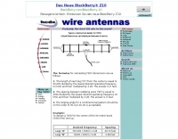
 Ever need a way to estimate the amount of wire to add to or remove from a center-fed wire dipole antenna to achieve resonance at a desired frequency? This article help to determine correct wire lenght.
 -
 Mounting on Roof or at Ground Level? Why ground plane antenna works better at lower level.
 -
 Blue Mountains Amateur Radio Club located in the Blue Mountains west of Sydney. Resources and Information for members and all radio amateurs.
 -
 The **Solarcon A99** vertical antenna, a half-wave over a quarter-wave variable mutual inductance design, primarily serves the 11-meter CB band but also finds use on 10 and 12 meters for amateur radio operators. Its simple construction, consisting of three fiberglass sections and a 16 AWG radiating element, makes it an accessible option for new operators or those seeking an easy-to-install base station antenna without complex mounting requirements. Despite claims of 9.9 dBi gain being widely considered exaggerated, and a manufacturer rating of 2000 watts power handling often viewed with skepticism (with 300 watts suggested as a practical limit), the A99 maintains popularity due to its low cost and ease of deployment. It typically tunes to a 1.2-1.3 SWR out of the box, requiring minimal adjustment via its two tuning rings. Its high angle of radiation allows for effective local communication even when mounted at low heights, such as 8-10 feet off the ground. However, the A99 is known for significant RF bleed-over issues, particularly when operated with higher power or mounted close to residential electronics. While its internal design is often described as cheap, the antenna exhibits remarkable durability, frequently lasting a decade or more in various weather conditions. Its affordability and straightforward setup continue to make it a go-to choice for many radio enthusiasts.
 -
 During a club's "Filetto Day" event, a comparative field test was conducted between a **Buddipole** antenna and a homemade 20/40-meter wire dipole. The author, IW5EDI, performed this personal evaluation from a mountain top at 1500 meters above sea level, utilizing a Yaesu FT-857D transceiver to switch between antennas. The observations on the 20-meter band indicated that the wire dipole consistently delivered significantly stronger signals compared to the Buddipole. Additionally, the Buddipole exhibited higher levels of **QRM** during the listening tests. The commercial Buddipole, known for its multiband capability and compact size with a self-supporting tripod, was contrasted with the simpler, larger wire dipole, which required a fiberglass fish pole for support. This direct comparison highlights practical differences in performance and deployment between a popular portable commercial antenna and a basic wire antenna in a real-world operating environment.
 -
 Constructing a high-power 70cm solid-state amplifier presents unique challenges, particularly when aiming for 500 watts output using modern LDMOS devices. This resource details the author's experience building a 70cm amplifier based on a _Freescale MRFE6VP5600H_ transistor, initially from an RFHAM kit. It meticulously outlines the necessary modifications to achieve advertised performance, including optimizing input and output matching, correcting bias circuitry, and ensuring proper output balun connections for stability. The author shares specific adjustments, such as trimming the prototyping board for better transistor fit, drilling additional mounting holes for improved heat sinking, and replacing original matching capacitors with a single _20pf MIN02 metal mica_ for superior output. A critical fix involved jumpering gate decoupling pads to balance the push-pull transistor halves, which increased output to 580W and improved IMD. The resource also highlights a crucial correction to the output balun connection, initially reversed in the _Dubus_ article schematic, which resolved intermittent stability issues. Test results are provided, showing input power, output power, and drain current at 50V, demonstrating the amplifier's performance after modifications. This practical account offers valuable insights for hams undertaking similar high-power UHF amplifier projects, especially those working with LDMOS devices and kit-based constructions.
 -
 Operating a ham station often involves encountering radio frequency interference (RFI), RF feedback, or RF burns, which are frequently misattributed to poor equipment grounding. This resource meticulously dissects these assumptions, asserting that RF grounds on the operating desk often merely mask more significant system flaws. It identifies five primary causes for RF problems, including antenna system design flaws, proximity of the antenna to the operating position, DC power supply ground loops, equipment design defects, and poorly installed connectors or defective cables. The content emphasizes that issues like "hot cabinets" or changes in SWR when connecting a ground indicate substantial RF flowing over wiring or cabinets, a phenomenon known as common-mode current. The article provides detailed explanations of common-mode current generation, particularly from single-wire fed antennas like longwires, random wires, and OCF dipoles, which inherently present high levels of RF in the shack. It also illustrates how vertical antennas, lacking a perfect ground system, can excite feed lines with significant common-mode current. Through simulations, the author demonstrates how a dipole without a proper _balun_ can cause RF problems at the operating desk, showing current patterns and voltage distributions on feed line shields. The discussion extends to the proper application of _RF isolators_ and _ferrite beads_, clarifying their role in modifying common-mode impedance on cable shields and cautioning against their use as a band-aid for fundamental system defects. The resource advocates for correcting the actual source of RF problems, such as antenna system issues or poor connector mounting, rather than relying on internal shack grounding or isolators. It highlights that properly functioning two-conductor feed lines, like coaxial or open-wire lines, should result in minimal RF levels at the operating position, even without a desk RF ground. The author shares personal experience, noting that his stations since the late 1970s have operated without RF grounds at the desks, relying instead on proper antenna system design and feed line integrity.
 -
 Lido Radio Products specializes in **no-holes mounting solutions** for a wide array of mobile electronic devices, including amateur radio transceivers, smartphones, and tablets. Their product line features cup holders, vent mounts, and window mounts, designed to secure equipment without permanent modifications to a vehicle's interior. The company supports various brands such as Icom, Yaesu, Kenwood, Motorola, Hytera, and Vertex, catering to both amateur radio operators and land mobile users. My own experience with similar mounting systems for mobile operations confirms the utility of a secure, non-invasive setup. A stable mount prevents equipment from becoming a projectile during sudden stops or turns, a critical safety consideration for any mobile station. Lido's focus on specific radio brands suggests a tailored approach to fit and function. They also provide individual parts to customize existing mounts, allowing operators to adapt solutions to unique shack or vehicle configurations. This modularity is a significant advantage for hams who frequently reconfigure their mobile setups or integrate new gear.
 -
 This online project guide details the construction of a homebrew boom microphone system. It details the assembly of a microphone shell from a 3/4" PVC pipe section and an end cap, requiring a drilled hole for a snug fit of the electret or condenser mic element. The internal wiring schematic specifies a **2.2 K** resistor and a **47 uF** polar capacitor for signal conditioning, with a circuit diagram provided for integration with IC-706 series transceivers. The guide outlines the use of CAT-5 cable for internal connections, incorporating strain relief at the rear of the mic shell, and an inline 3.5 mm jack to facilitate an external _PTT_ line, designed for a foot-mounted switch. Further construction involves fabricating a microphone shock mount from a 2-inch PVC connector, detailing the creation of four "fingers" and the insertion of screw-eyes for attaching elastic bands, which are twisted 180 degrees for tensioning and vibration isolation. A foam wind screen is also incorporated into the microphone assembly, secured with adhesive. The boom arm itself is repurposed from an articulated architect lamp, with the original lamp assembly converted into a **60 watt** resistive load for testing power sources. Microphone cabling is secured to the boom arm using wire ties, ensuring sufficient slack at hinge points to maintain articulation. The boom base is mounted to a bookshelf, requiring specific positioning to achieve proper microphone placement in front of the operator. Performance evaluation of the microphone system is conducted through on-air audio signal reports from other amateur radio operators. DXZone Focus: Online Project Guide | Boom Microphone Construction | Electret Mic Element | PTT Line
 -
 The Superantennas MP-1 portable HF antenna is analyzed for its design and field performance, particularly its high-Q loading coil and 3/8-inch mounting. The review details the antenna's construction, including an 8-inch vertical section, a large-diameter loading coil tuned by a sleeve, and a 4-foot whip that disassembles into six rods for transport. Initial testing with the supplied 10-foot ribbon cable "ground plane" yielded poor SWR and RF hot conditions, indicating an inadequate ground system. Further experimentation with longer radials and resonant counterpoises for each band improved matching and eliminated RF hot issues, but introduced significant operational complexity. The author notes the difficulty in optimizing both counterpoise length and coil setting without an antenna analyzer, and the sensitivity of the MP-1 to counterpoise deployment. The review also discusses the recommendation to tune for maximum received signals rather than minimum SWR, often necessitating an external ATU due to the antenna's typical low impedance. The **MP-1**'s critical dependence on resonant counterpoises for effective operation, especially when elevated, is highlighted as a major drawback for portable use. The author ultimately sold the antenna, concluding that despite its sound technical design, its fussy nature and the need for extensive counterpoise management or an ATU detract from its portability and convenience compared to simpler, less expensive dipole solutions. The **Superantennas MP-1** is deemed a flawed portable antenna, requiring considerable effort to achieve its claimed performance.
 -
 A synthesized 2.3 GHz Amateur Television (ATV) transmitter design, conceived by Ian G6TVJ, is presented, targeting broadcast-quality video performance on the 13cm band and extending up to 2.6 GHz. The core of the design utilizes a commercial Z-comm Voltage Controlled Oscillator (VCO) that tunes from 2.2-2.7 GHz, providing a +10 dBm output and simplifying RF alignment. This VCO's stability, originally intended for narrowband applications, readily accepts high-frequency video modulation, contributing to the transmitter's robust performance. The exciter stage, incorporating a Mini Circuits VNA 25 MMIC amplifier, boosts the signal to +16dBm, while a Plessey SP4982 prescaler divides the output frequency for the synthesizer. The synthesizer employs a Motorola MC145151 CMOS parallel IC, favored over the common Plessey SP5060 for its superior video modulation characteristics and ease of programming without microprocessors. This choice addresses issues like LF tilt and distorted field syncs often seen with SP5060 designs, particularly when operating through repeaters or over long distances. The MC145151 divides the signal further, enabling precise frequency stepping, with programming handled by EPROMs for channel selection and LED display. The loop filter network, critical for video integrity, was developed through experimentation to prevent the PLL from reacting to video modulation, ensuring a clean transmitted picture. The transmitter incorporates a Down East Microwave commercial power amplifier module, delivering approximately 1.6W output, driven by the exciter through a 3dB attenuator. Construction involves surface-mount SHF components on micro-strip lines etched onto double-sided fiberglass board, housed within a tinplate box. The design boasts no AC coupling in the video path, preserving low-frequency response, a common failing in other ATV transmitters. Performance tests with a 50Hz square wave revealed no LF distortion, and a calibrated "Pulse & Bar" signal showed a near 100% HF response, demonstrating its capability for high-quality ATV transmissions.
 -
 Documents the construction of a **VHF/UHF** antenna addition for the Buddipole HF antenna system, leveraging the existing Versa-Tee component. The project details the fabrication of a custom antenna mount from angle aluminum, including specific drilling and tapping for 3/16"-24 bolts, and the creation of radials from Simpson Strong Tie Insulation Supports. It specifies radial lengths for 70 centimeters (6 inches from the center stud) and 2 meters (19 1/4 inches), noting the use of wire nuts for safety. The resource outlines the construction of a mast from 1/2" ID PVC conduit, connected with 3/8"-24 connecting nuts and bolts, mirroring the Buddipole's modular design. It describes the integration of a mobile dual-band antenna with a 3/8"-24 mounting stud and the custom coax setup with BNC and **PL-259** connectors. Field testing with an FT-817ND and a separate dual-band SWR meter confirmed good SWR on both 2 meters and the 440-450 MHz section of 70 centimeters, with positive reception reports during Field Day activities. Further, the article describes the creation of a custom carrying solution, including a 22-inch tripod bag and a fabric roll-up, to emulate the portability of the original Buddipole system.
 -
 Demonstrates the complete design and development process for a **Low Noise Microwave Amplifier** (LNA), beginning with conceptual design and progressing through prototyping. The tutorial series covers the initial stages of a single-ended first gain stage, focusing on critical parameters such as noise figure, gain, and stability. It systematically details the theoretical underpinnings and practical considerations for achieving optimal performance in microwave frequency applications. This resource provides a structured approach to LNA construction, enabling radio amateurs and RF engineers to understand the iterative steps involved in realizing high-performance receive-side amplification. It offers insights into component selection, impedance matching networks, and the measurement techniques required to validate design specifications, particularly for **microwave** band operation where noise performance is paramount.
 -
 Twenty-four repeaters, including D-STAR and Fusion systems, are maintained and operated by MARCA Inc., primarily located on Arizona mountaintops and around the Phoenix metropolitan area. The organization, holding the callsign _W7MOT_, facilitates a wide range of amateur radio activities, such as ARRL Field Day events near Forest Lakes, Arizona, and participation in ARRL FMT contests. Members engage in antenna experimentation, construction, and maintenance trips to repeater sites. The club's interests span diverse topics, including HF voice, digital modes like _WSPR_, _WSJT-X_ (FT8, FT4), and CW, alongside DXing, MESH networking, and EOC operations. It supports technologies from SDR radio building to antique radio restoration and computer-based operations like Echolink, fostering a Single Board Computer (SBC) and Raspberry Pi group. Monthly meetings, held on the third Tuesday, feature business discussions and guest presentations, with informal summer gatherings and an annual holiday dinner in December. Monthly VE testing sessions for Technician, General, and Extra Class licenses are conducted by Ray Vasquez, K4RMV. Post-meeting discussions often cover specialized interests such as repeater operations, technical topics, D-STAR, SDR, APRS, Fusion, and Raspberry Pi projects.
 -
 First released around 1995 and significantly redesigned as QWTelnet 2, this software provides a dedicated interface for monitoring DX-Cluster traffic via Telnet. It integrates a **SOTAwatch parser** with configurable audio alerts, allowing operators to receive notifications for specific search patterns in DX-Cluster remarks without constant screen attention. The application also supports parsing for **GMAwatch (German Mountain Award)**, providing alerts for German Mountain Award activations. QWTelnet 2.4.0, released on 07-APR-2012, runs on Windows (tested on W7) and is distributed as a ZIP file containing the `qwtelnet.exe` executable. It does not require a formal installation process; users simply extract and run the program. The software can display DX information for single bands, integrate with the Reverse Beacon Network, and link to external web resources for DXCC and SOTA information. It also supports local reference files for IOTA, WFF, and RDA awards, which users must source and place in the `qwtelnet/files` directory. For IOTA data, users can convert `IOTA.CSV` from UCX-Log or `DX4WIN_IOTA.TXT` into `iota.csv`. WFF and RDA reference files are directly sourced from their respective websites.
 -
 This resource documents numerous QRP (low power) portable amateur radio operations conducted by W1PID, Jim Cluett, primarily from various outdoor locations in New Hampshire. The content includes detailed accounts, photographs, and operational specifics for over 350 individual "QRP Adventures," often involving hiking, biking, or kayaking to remote sites. Each entry typically highlights the location, date, bands and modes used (frequently CW on HF), and notable DX contacts made with minimal power, sometimes as low as 200mW WSPR. The site serves as a chronicle of practical QRP field operation, demonstrating successful DXing and contesting from challenging environments. It showcases diverse operating scenarios, from mountaintops like Cannon Mountain and Knox Mountain to lakeshores, riverbanks, and even marine mobile operations. The documented contacts span numerous DXCC entities across Europe, Asia, and the Americas, providing empirical evidence of QRP's efficacy in varied propagation conditions and terrains. Specific events like the Worked All Germany contest, 13 Colonies Event, and CWT sprints are also featured.
 -
 When assembling a robust shack, the quality of interconnects often determines overall system integrity and signal fidelity. Neutrik, with over 50 years in the connectivity sector, specializes in professional-grade connectors that withstand rigorous use in entertainment and industrial applications. Their product range includes XLR, speakON, powerCON, and opticalCON series, which are frequently adapted by hams for critical station infrastructure, particularly in contesting or DXpedition environments where reliability is paramount. Amateur radio operators often repurpose these durable connectors for antenna switching matrices, audio interfaces for digital modes, or power distribution systems. The robust locking mechanisms and high-quality contact materials found in Neutrik products ensure stable connections, minimizing intermittent faults that can plague field operations or even fixed station setups. This attention to mechanical and electrical integrity aligns well with the demands of high-power RF environments and sensitive receive chains. While primarily serving the pro-audio and video markets, the engineering principles behind Neutrik's designs translate directly to the needs of radio amateurs seeking superior performance and longevity from their cabling and connection points. Their commitment to innovation, as highlighted by their 50-year journey, suggests a continuous evolution of products that could benefit future amateur radio applications.
 -
 Designing and constructing a two-element receiving loop antenna array for HF operation involves specific considerations for achieving high directivity and noise reduction. This resource details a homebrew system comprising two 30-inch diamond-shaped loops, spaced 20 feet apart, which are fed through mast-mounted preamplifiers and passive signal combiners. The operational principle relies on adjusting phase delays between elements via precise _Belden 8241_ coaxial cable lengths, optimized for specific bands from 160m to 20m. Performance data, derived from _EZ-NEC_ modeling, illustrates consistent 90° azimuth-plane beamwidth and low take-off angles across the target bands, with _Receiving Directivity Factor_ (RDF) values comparable to a 300-foot Beverage antenna. The article presents detailed elevation and azimuth plots for 20m, 30m, 40m, 80m, and 160m, demonstrating the array's ability to provide strong response at low DX angles while also supporting _NVIS_ signals. Key components like the _DX Engineering RPA-1_ preamplifier and _DXE RSC-2_ signal combiner are discussed, alongside the importance of impedance matching to preserve antenna patterns. The construction emphasizes self-contained elements that do not require ground radials, offering a compact solution suitable for suburban environments and stealth installations, with a focus on optimizing receive performance independently from transmit antennas.
 -
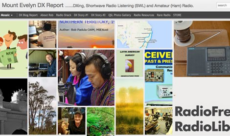 A nice blog about DXing, Shortwave Radio Listening (SWL) and Amateur (Ham) Radio by VK3BVW
 -
 One of the featured products, the V350 CAMP, is a multiband vertical antenna covering 6 to 80 meters, priced at R$ 799,90, demonstrating the range of ready-to-use solutions available. The inventory includes various antenna types such as **HF**, **VHF**, and **UHF** designs, along with dual-band options like the J-Pole Dual V/UHF for R$ 235,00. For those building their own arrays, the store stocks essential components like element holders, clamps, junction boxes, and aluminum plates, alongside specialized items such as the KIT Isolador Central Dipolo - 01DX for R$ 99,90. The shop also provides a comprehensive selection of installation hardware, including diverse antenna mounts, PTT supports, and various coaxial cables like RG58 and RG213, with prices up to R$ 849,90 for RG213. Connectors such as UHF male PL259 and various adapters are readily available, ensuring compatibility for different setups. Additionally, specialized items like side handles for popular transceivers such as the FT857/891 and IC7300 are offered, catering to specific equipment needs. Beyond antennas, the store supplies practical accessories like transport bags, 12V power cables for transceivers, and even branded merchandise like the Antena Kit mug. Rodrigo Gonçalves, PP5BT, manages the operation from Blumenau, SC, Brazil, providing direct contact via WhatsApp at +55 47 9.9985.0155.
 -
 Low-frequency (LF) radio time signals, operating primarily in the 40–80 kHz range, are broadcast by national physics laboratories for precise clock synchronization. Transmitters like **JJY** (40 kHz, 50 kW; 60 kHz, 50 kW), RTZ (50 kHz, 10 kW ERP), MSF (60 kHz, 15 kW ERP), WWVB (60 kHz, 50 kW ERP), RBU (66.66 kHz, 10 kW), and DCF77 (77.5 kHz, 50 kW) cover vast geographic areas, often several hundred to thousands of kilometers. LF signals offer distinct propagation advantages over higher-band transmissions such as GPS. Their long wavelengths (3–6 km) enable effective diffraction around obstacles like mountains and buildings. The ionosphere and ground act as a waveguide, eliminating the need for line-of-sight and allowing a single powerful station to cover extensive regions. Ground wave propagation minimizes ionospheric variability effects on transmission delay, and signals penetrate most building walls effectively. Robust and low-cost receivers, often priced at 20–30 USD/EUR, are widely used in radio clocks. These receivers typically comprise a tuned ferrite core antenna, a receiver IC (e.g., Atmel T4227, U4223B, MAS1016) for amplification and AM detection, and a microcontroller for decoding the time signal and phase-locking a local clock. Specific components for DCF77, MSF, and WWVB are readily available from vendors like HKW Elektronik and Ultralink.
 -
 The TECLA Thirty, an early wireless age crystal set, is featured among a gallery of over 100 collectible headphones, with detailed close-up photos of vintage models. Several pages offer vintage headphones for sale, including Brandes, Baldwin, and Western Electric, suitable for crystal set use or collecting. Construction details are provided for a reproduction KILBOURNE AND CLARKE crystal set, built with vintage 1920s parts and featuring a miniature variable condenser for fine tuning. The resource also presents a project for a simple crystal radio and a 1-tube amplifier, complete with a schematic and component diagram, suitable for driving a horn speaker or amplifying weak signals for headphones. Instructions for mounting argentiferous galena detector crystals are included, along with information on MRL Handbooks covering crystal detectors and modern diodes. Additional projects include a 2A3 single-ended triode tube amplifier and two stereo tube amps using 12AX7, 6V6, 5Y3G, 6SN7, VT-25, and 5U4G tubes.
 -
 Demonstrates the practical application of APRS (Automatic Packet Reporting System) through the lens of HB9PVI's activities in Switzerland. It covers the system's core function of reporting geographical positions and telemetry data from various objects, including mobile stations, aircraft, and the ISS, distributed via packet radio and internet gateways. The resource highlights the routing paradigm shift introduced in April 2005, specifically the recommendation to use _WIDE1-1_ instead of RELAY and WIDE for digipeating to reduce duplicate packets. The page presents real-time maps displaying the positions of amateur radio stations in Switzerland and around Bern, updated every few minutes. It details specific callsigns like _HB9BA-2_ (HB9PVI's home QTH), _HB9BA-8_ (a weather station), and _HB9BA-4_ (a WIDE digipeater on Weissenstein mountain), providing context for their roles within the local APRS network. Links to track HB9PVI's mobile operations (_HB9PVI-9_) and handheld devices (_HB9PVI-15_, _HB9PVI-7_) are also provided. Furthermore, the resource curates a list of APRS software options for various operating systems, including _JavAPRS_ for Europe, _UI-view_, and _X-Astir_ for Linux, alongside digipeater/IGATE software like _DiXPRS_. It also offers downloadable APRS information, including a PDF article by HB9PVI and HE9ZGN, and a PowerPoint presentation in German, making it a repository of practical and historical APRS data.
 -
 High Speed Multimedia (HSMM) radio, as introduced by John Champa, K8OCL, represents a significant advancement in amateur radio's digital capabilities, moving beyond traditional keyboard modes like packet radio. This initiative, driven by ARRL's Technology Task Force, focuses on developing high-speed digital radio networks capable of up to 20 megabits per second. HSMM primarily facilitates digital voice (DV) and digital video (ADV), enabling real-time video transmission from emergency scenes to an EOC without expensive ATV gear, often requiring only a laptop, a PCMCIA card, a digital camera, and a small antenna. The working group's initial efforts concentrate on cultivating microwave skills within the amateur community to build and support portable and fixed high-speed radio-based local networking, or **RLANs**. These networks prove invaluable for RACES and ARES organizations, as well as homeland security and other emergency communications. Field Day exercises and simulated emergency tests (SETs) are encouraged to hone skills in rapid site surveys and deploying broadband HSMM microwave radio networks, with examples like linking Field Day logging stations or antenna test results at the Midwest VHF-UHF Society Picnic 2003. Getting started with HSMM often involves adapting off-the-shelf **IEEE 802.11** (WiFi) equipment to comply with amateur radio regulations, typically operating in the 2.4 GHz ISM bands. While consumer WiFi gear has range limitations under Part 15 rules, proper setup under amateur regulations can extend coverage significantly, with test networks like the Hinternet achieving 5-15 mile ranges at 54 M bit/s using small mast-mounted dish antennas. Careful selection of equipment with external antenna ports, high transmit power, and low receive sensitivity is crucial, along with using low-loss coaxial cable like LMR-400 for optimal performance at these frequencies.
 -
 MARCA, Inc. operates approximately 24 repeaters across Arizona mountaintops and Phoenix-area rooftops, supporting modes like D-STAR and Fusion. The club, holding the **W7MOT** callsign, engages in diverse activities including ARRL Field Day events near Forest Lakes, AZ, ARRL FMT contests, and antenna experimentation. Members actively participate in HF operations such as voice, digital, CW, DXing, and various digital HF modes, alongside MESH and EOC operations within the valley. The club's interests span a broad technical spectrum, from SDR radio building to antique radio restoration, and include modern digital modes like WSPR, WSJT, FT8, and FT4. They also explore computer-based operations such as Echolink, fostering a dedicated Single Board Computer (SBC) and Raspberry Pi group. Monthly VE testing sessions for Technician, General, and Extra Class licenses are conducted by Ray Vasquez, K4RMV. Meetings are held on the third Tuesday of each month, typically lasting two hours, with a business segment followed by a technical presentation. These gatherings occur in-person at IHop in Mesa, AZ, and concurrently via Zoom, accommodating both local members and winter visitors. Informal chat groups often form post-meeting to discuss specialized topics like D-STAR, SDR, APRS, MESH, and Fusion.
 -
 This Field Day Vertical Antenna project is the result of many years of attending various field day sites and realizing that what was needed is a simple, easy to assemble vertical antenna. The design of this Field Day Antenna is not very novel and leverages ideas from Butternut verticals and ARRL publications. The one essential requirement was that the antenna can be raised by just one person. The design of this Field Day Antenna is an above ground mounted ground plane vertical.
 -
 Mounting on roof at the right ground level can greately impact on antenna performances because will affect the radiated angle of energy.
 -
 This article describes the construction of a simple dual-band VHF/UHF end-fed vertical dipole antenna designed for local repeater access using an Icom IC-705 radio. Built from a single piece of RG58U coaxial cable, the antenna consists of a 460mm exposed inner conductor, 450mm of intact coax, and a 9-turn choke balun wound on a 27mm former. Mounted on a 10m Spiderpole, the antenna achieves excellent SWR readings (<1.2:1 on 2m, <1.5:1 on 70cm) and provides effective coverage of local repeaters with unexpected reach into distant locations.
 -
 The 222 MHz Transverter project, based on Zack Lau's (W1VT) original July 1993 QEX magazine design, provides an IF of 28 MHz for both transmit and receive paths. Rick Bandla (VE3CVG) contributed supplemental notes and construction details, including modifications to achieve 10 mW output power from an initial 4 mW PEP. The design incorporates three distinct boards: a Local Oscillator (LO), a Transmitter (Tx), and a Receiver (Rx), with an estimated parts cost of just over $150 CDN, significantly less than commercial kits. Construction involves both through-hole and surface-mount components, with specific guidance on mounting MAV and MAR devices, grounding techniques, and component selection. The project details include parts lists, schematics for the LO, Tx, and Rx, and board layouts. Troubleshooting advice emphasizes sequential testing, starting with the LO, then Tx, and finally Rx, using a 194 MHz and 222.100 MHz capable FM handheld for signal tracing. Further enhancements are discussed, such as an optional Tx driver stage to boost output to 100 mW and the potential modification of a Motorola Maxor 80 PA for 222 MHz SSB/CW operation. The resource also covers practical aspects like power attenuation pads for IF radios (e.g., FT817) and considerations for enclosure design, including repurposing a Maxor 80 case. Performance reports indicate successful 70 km contacts with only 4 mW output.
 -
 The Pikes Peak Radio Amateur Association (PPRAA) serves as an ARRL Special Service Club, providing a calendar of events and activities for its members and the wider amateur radio community. The resource details upcoming events such as the USS Pueblo Memorial Museum Ships Weekend activations, a Cubical Quad Antenna Workshop, LARCFest, and various hamfests including Dayton Hamvention and Duke City Hamfest. It also lists on-air activities like a FreeDV digital voice mode event on 10 meters, a Black Friday Simplex Event on 2M and 70cm, and a 10m event for Technician class operators, emphasizing SSB privileges from 28.300 to 28.500 MHz. The PPRAA's event schedule includes educational opportunities like a Technician Class and a Soldering Workshop, alongside social gatherings such as the PPRAA Picnic and Car Show. Past event summaries highlight successful activities like the 2024 Megafest Raffle, Winter Field Day, and multiple fox hunts utilizing frequencies like 147.420, 147.480, and 147.540 MHz. The club actively supports POTA activations, exemplified by their AF0S park activation at Cheyenne Mountain State Park, and participates in historical commemorations like the USS Pueblo Memorial operations, demonstrating a broad engagement across various amateur radio facets.
 -
 Fully functional weathervane conceals an efficient 2- meter base-station antenna. Your Neighbors and HOA won’t know it’s there and they will love the rooster-vane. The Rooster-Tenna is a covert 2-meter ham radio antenna disguised as a functional weathervane, ensuring seamless integration into residential environments. This improved version features a wide-spaced parallel-fed folded dipole in a compact skeleton slot design. Constructed from aluminum tubing and acrylic supports, it offers omnidirectional, vertically polarized performance suitable for repeater and satellite use. Easy to mount and tune, it achieves a low SWR across the 2m band. With 3D-printable parts available, the Rooster-Tenna blends practicality with stealth, making it an ideal solution for HOA-restricted areas