Search results
Query: fet amplifier
Links: 39 | Categories: 0
-
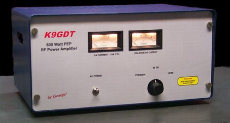 Schematics plans by K9GDT and all infos to build a 600 Watt HF Amplifier. The amplifier uses four Motorola MRF150 50 volt TMOS power FETs configured in push-pull/parallel and biased for class AB linear operation.
 -
 Over 25,000 amplifiers and sub-assemblies were produced by Angle Linear for the communications industry over a 40-year period. The company specialized in **high-linearity RF products**, focusing on preamplifiers, bandpass filters, and receiver multicouplers. Specific product lines included PHEMT and GaAs FET preamplifiers, offering both quadrature and single-ended configurations for various signal levels. The offerings encompassed coaxial and combline bandpass filters, along with integrated filter-preamplifier assemblies. The company also provided custom RF assemblies, addressing applications such as MRI preamplifiers, passive radar, and EME (moon bounce). Their product range covered VHF and UHF frequencies, including specific designs for 2m, 70cm, and 23cm bands, often featuring high IP3 performance. Technical documentation, such as filtering application notes and duplexer theory, was also associated with their product offerings.
 -
 Design of a preamplifier for 144 MHz with 1 dB NF and 23 dB gain using BF981. This amplifier is using a low cost silicon MOSFET (BF981 from Philips) to give more than 20 dB gain with around 1 dB noise figure on 2 meter.
 -
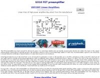 This FET preamplifier has been around for almost 25 years. It is extremely reliable and can handle several watts directly into either the input or the output without failure.
 -
 This project uses a widely available IRF510 MOSFET, work on HF 80, 40, 30, 20 and 17 meter bands
 -
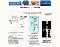 KD9JQ 2 meter GaAsFET preamplifier by KD9JQ
 -
 Constructing a high-power solid-state amplifier for HF operations presents unique challenges, particularly when aiming for significant output like 600 watts. This project details an amplifier design employing **Motorola MRF150** FETs, a common choice for their robust performance in RF power applications. The design emphasizes achieving substantial power output, a critical factor for effective DXing and contesting, where every decibel can make a difference in signal propagation and readability. While specific circuit diagrams or construction details are not directly presented on the current page, the mention of MRF150 FETs points towards a design that would typically involve push-pull configurations, impedance matching networks, and robust power supply considerations to handle the high current demands. Such amplifiers are often built with an eye towards linearity and efficiency across the HF bands. Amateurs pursuing similar high-power solid-state projects often share insights on thermal management, intermodulation distortion, and component sourcing, all vital for a stable and reliable amplifier capable of delivering 600 watts into a proper antenna system.
 -
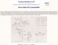 On 23cm the best way to obtain a good RX-sensitivity is to use a GaAs-FET in the front-end, since these devices show very low noise figures.
 -
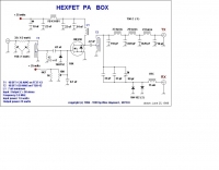 80m hexfet power amplifier by W7ZOI
 -
 Advanced QRP Low Cost Mosfets HF Linear Amplifier with schematics, IMD, gain data and more. Six articles about amateur radio.
 -
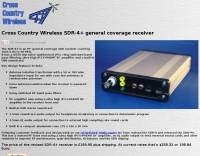 SDR Receiver a compact high performance HF software defined radio receiver designed to be used in fixed or portable stations. Version 2 of the receiver is now available. It now has an RF pre-amplifier using a power MOSFET and other revisions to improve it's performance both as a stand alone receiver and as an IF panadaptor with HF and VHF transceivers.
 -
 The I0JXX is an italian company that offers market their projects, also sells electronic products of high quality, both for Ham, both Broadcast and their accessories. VHF Antennas, mosfet power amplifiers, filters, insulators, power dividers, telescopic poles, antenna masts
 -
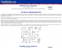 The 60 Watt linear amplifier is simple all solid state circuit using power mosfet IRF840.
 -
 Low power VHF RF amplifier with VMP1 Mosfet by IZ1BTS IK1XPD
 -
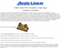 Angle Linear has been producing GaAs FET preamplifiers since 1980
 -
 A solid state linear based on EB104 Motorola Engineering Bulletin by Helge Granberg. It uses 4 MRF150 FETs in push-pull parallel to acheive 600 Watts from about 6 Watts drive
 -
 VHF UHF Amateur radio antenna and antenna parts, accessories for homebrewers, antenna kits, tubes, antenna masts, antenna tripores, insulators, power amplifier mosfet, power splitters by I0JXX
 -
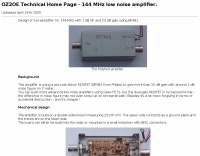
 Operating on the 2200m band (135.7-137.8 kHz) often presents challenges for amateur radio transceivers, which typically exhibit poor receiver performance at these very low frequencies. This project addresses the issue by providing a design for a dedicated 137 kHz antenna preamplifier, specifically tailored to improve signal reception for radios such as the _Yaesu FT-817_. The preamplifier circuit utilizes a low-noise FET input stage, crucial for minimizing self-generated noise and maximizing the signal-to-noise ratio from weak LF signals. The design includes a detailed schematic, component values, and construction notes, enabling homebrewers to build a functional unit. The goal is to achieve significant gain, making the faint signals on 2200m more discernible and improving overall band usability. Key design considerations include impedance matching to typical antenna systems and ensuring stable operation across the narrow LF segment. The circuit aims for a **low noise figure** and sufficient amplification to overcome the inherent limitations of general-purpose HF transceivers when operating below **200 kHz**.
 -
 This document details the design and construction of the PA70H, a 50-watt RF amplifier for the 70MHz (4-meter) amateur radio band. Built around the Mitsubishi RD70HVF1 MOSFET transistor, the amplifier delivers 45-55W output with 3-5W input power while operating on 13.8V DC at approximately 7-8A. The PCB design incorporates multiple protection circuits including overcurrent, SWR, and temperature control. The amplifier features various control modes including GND PTT, +13.8V PTT, and RF VOX. Two versions are available: PA70HLI (requiring 100mW input with additional driver) and PA70H (for 3-5W input). The comprehensive documentation includes circuit diagrams, assembly instructions, and performance data showing successful operation from both 100mW and 3.5W input sources.
 -
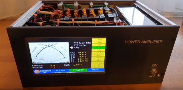 A comeplete home made 600W LDMOS RF power amplifier. Settings can be made on a 7-inch touch screen, and on this screen you can see a lot of useful information during operation, such as output power, temperature, SWR, and so on. The power amplifier includes 2 MRF300 LDMOS FETs and several built-in sensors. The amplifier also contains several types of protection functions like too high current, too high swr, too high temperature, etc.
 -
 Extremely reliable FET preamplifier can handle several watts directly into either the input or the output without failure
 -
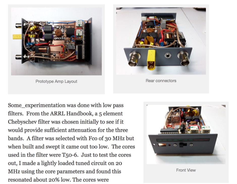
 The resource details the construction of a homebrew 50-watt FET amplifier, based on Don W6JL's _QST Homebrew contest_-winning design from 2009. It functions as an afterburner for QRP transceivers, providing a **12dB** power lift. The amplifier utilizes IRFZ24N FETs and covers the 80, 40, 30, and 20-meter bands, with the 20m LPF extending to 17m. Key technical aspects include an FT37-43 transformer for the input network, a relay-switched 3dB pad for lower bands controlled by an _Arduino Nano_, and an RF-actuated T/R switch. The LPF board integrates four relay-switched filters rated for 50 watts, using capacitors with a minimum 250VDC rating. Performance measurements indicate a power gain ranging from **4.4dB** on 20m to 8.1dB on 80m, with a required drive power of approximately 5 watts. The article also discusses thermal management, current limiting considerations, and component sourcing.
 -
 Protecting amateur radio equipment from transient overvoltages requires robust lightning and surge protection, which is the focus of Electronic Specialty Products. The company provides various devices, including coaxial lightning arrestors for antenna feedlines and surge protectors for AC power lines and data circuits. These devices are engineered to divert high-energy surges, such as those caused by direct or indirect lightning strikes, away from sensitive transceivers, amplifiers, and computer components, thereby preventing catastrophic damage. Key products include the _Coaxial Lightning Protector_ series, designed for various impedance levels and frequency ranges up to 3 GHz, and the _AC Line Surge Protector_ for shack power distribution. Effective deployment of these protection devices can significantly reduce the risk of equipment failure and ensure operational continuity during severe weather. For instance, a properly installed coaxial arrestor can handle peak currents of **20 kA**, while AC line protectors offer clamping voltages typically below 400V. Comparing different models reveals varying levels of insertion loss and return loss, with some coaxial units exhibiting less than 0.1 dB loss at 500 MHz, making them suitable for high-performance HF and VHF/UHF operations. Integrating these components into a comprehensive grounding system is crucial for achieving maximum protection against both common-mode and differential-mode surges.
 -
 Linear Amp UK specializes in the design and production of high-quality linear amplifiers, offering models for HF, VHF, and UHF amateur and commercial applications. The company emphasizes nearly 30 years of experience in crafting each unit, ensuring robust performance and longevity. Their product line includes amplifiers engineered for a 100% duty cycle, promoting continuous and reliable operation across various modes. The amplifiers feature solid, dependable designs, ensuring quiet and effortless performance during transmission. Each unit is hand-built to stringent standards, reflecting a commitment to durability and operational stability. All products are CE approved, confirming compliance with European safety and environmental directives, and come with a standard two-year warranty, providing assurance to operators. Key specifications often include coverage for 1.8-30MHz (WARC bands), 50MHz, 70MHz, and 144MHz, utilizing tubes such as 811, 572, 811A, 572B, GS35, GS35B, 8877, 3CX1500, and _3CX1500A7_ in their designs.
 -
 An easy to build with a cheap HEMT FET Transistor Low noise preamplifier with FHX35LG based on JH0WJF design
 -
 A 160W linear amplifier for 4 meters band based on GI0GDP
 -
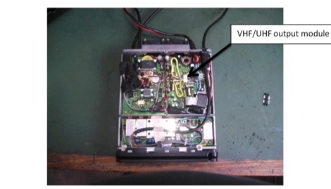 Replacing the Yaesu FT100D SRF7043 VHF/UHF RF MOSFET Power Amplifier
 -
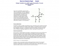 Design Guidelines for JFET Audio Preamplifier Circuits By Mike Martell N1HFX
 -
 An HF 10-20m portable RF power amplifier based on the RD16HHF1 FETS giving 25 W.
 -
 Selecting appropriate coaxial cable and wire for demanding amateur radio applications, particularly those involving high power or harsh environmental conditions, is crucial for maintaining signal integrity and operational safety. This resource details Harbour Industries' specialized offerings, which include Mil-Spec and commercial designs such as NEMA HP3/HP4 and SAE AS22759, suitable for aerospace, military, and industrial sectors. Their product line addresses the need for robust conductors capable of withstanding extreme temperatures and mechanical stress, often encountered in antenna systems or amplifier interconnections. The company highlights its AeroPOWER® Firezone M25038/3 cable, specifically engineered for high-temperature environments like aircraft engines. This particular product exemplifies their focus on solutions for critical infrastructure where reliability under adverse conditions is paramount. Such cables are relevant for hams building or maintaining stations in challenging climates or those operating high-power amplifiers where internal wiring must endure significant thermal loads. Harbour Industries also provides a range of high-performance cables designed to meet stringent specifications. Their expertise in high-temperature and high-performance cable manufacturing positions them as a supplier for specialized wiring needs beyond standard off-the-shelf options, ensuring durability and performance for advanced amateur radio setups.
 -
 Demonstrates the construction of a high-power 6-meter (50 MHz) amplifier, specifically designed for demanding modes like EME, TEP, and multiskip Es. It details the use of a _GU-43B_ tetrode in a grounded-cathode configuration, emphasizing the need for stabilized grid voltage and input capacitance compensation. The resource provides a comprehensive schematic, power supply design, and practical considerations for component sourcing, particularly for high-voltage and high-current sections. The builder achieved an output power of **1250 watts** with an anode current of 0.65 amperes and 3200 volts anode voltage. The article also covers the physical construction within a modified P6-31 enclosure, outlining the internal layout for RF and power supply sections, and includes photos of the completed unit. It highlights critical safety precautions for working with high voltages and reactive currents up to **20 Amperes** in the P-network.
 -
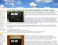
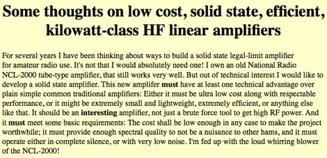 Thoughts build a solid state legal-limit amplifier for amateur radio use.
 -
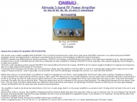
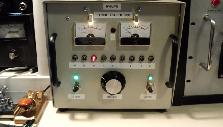 This is a Solid State Amplifier Project. It uses 4 MRF150 MosFet Power Transistors. The Power Supply Voltage is 50 VDC at 21.5 Amp. The max power available is 1,075 Watts. The Efficiency is about 65% +/- and runs Class AB Solid State.
 -
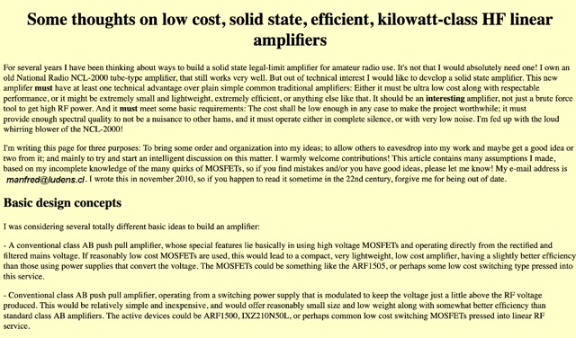 Not a project yet, but very theoretical thoughts about very practical amplifiers!
 -
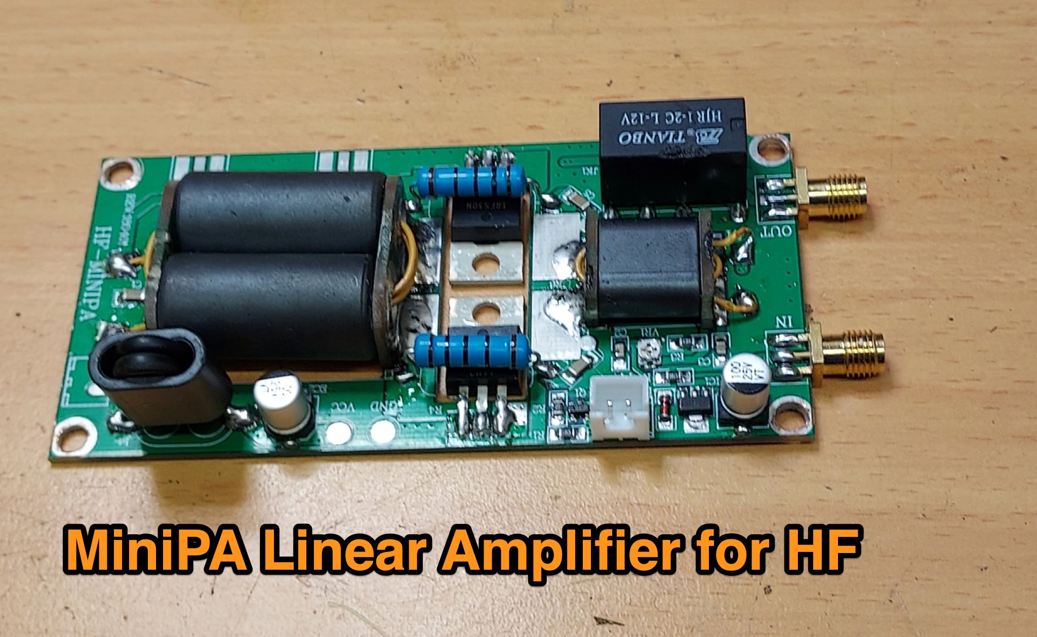 The MiniPA Linear Amplifier for HF page discusses the popularity of QRP for HF among ham radio operators, such as those using the Yaesu FT818 or low power SDR transceivers. It explores the use of cheap kits from eBay or Chinese suppliers to build a 70-100W SSB amplifier using IRF530 MOSFET transistors. The article provides a review of the MiniPA design, including its features, components, and assembly process. It also highlights the importance of using a heatsink and forced air cooling for optimal performance. This page is useful for hams looking to enhance their HF rig with a budget-friendly amplifier.
 -
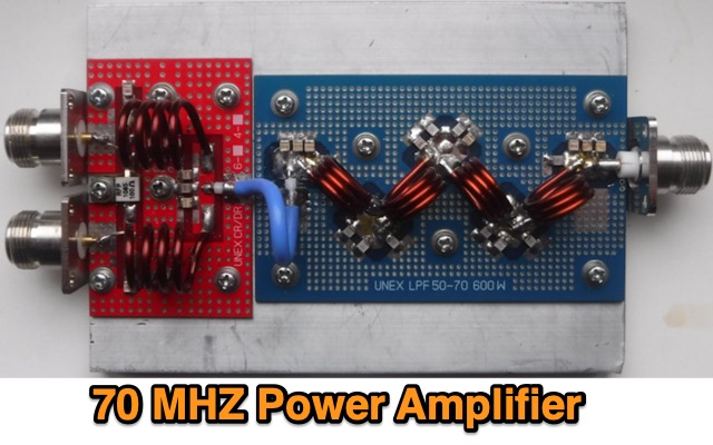 This PA has been designed by Sergey EX8MLE and uses three Mitsubishi RD100HHF1 FETs, Frequency Range 70 to 72 MHz
 -
 Integrating a _Software Defined Radio_ (SDR) into an existing ham radio setup involves connecting it with a standard transceiver (TRX), power amplifier (PA), and antennas. The core component is a splitter box that facilitates the connection between the TRX and the SDR, allowing for simultaneous operation without modifying existing equipment. In receive mode, the splitter ties the antenna inputs of both the TRX and a direct conversion receiver (DC RX) together. During transmission, the DC RX input is grounded via a fast telecom relay controlled by the transceiver's -SEND signal, incorporating a 10ms delay for safety. The splitter box includes a 3.7 dB input attenuator for impedance matching and acts as a protective fuse for the DC RX input. Ground loops are mitigated using common mode balun transformers, while the DC RX input is insulated with a broadband transformer. An audio switch box complements the setup, enabling users to listen to either the main transceiver, the SDR output, or both simultaneously. This configuration ensures noise immunity and safety, with the splitter housed in a screened box made from PCB material. On-air tests, such as the CQ WW 160m CW DX Contest, demonstrate the system's effectiveness, showcasing the SDR's ability to handle crowded band conditions with superior selectivity and dynamic range. The SDR's narrow bandwidth filters and waterfall display provide significant advantages, allowing operators to detect weak signals amidst strong interference. The integration of SDR with conventional radios offers enhanced operational flexibility and performance in challenging environments.
 -
 An Arduino-based interface provides a remote tuner call command for Icom **IC7700** and **IC7800** transceivers, addressing the lack of a built-in function for external tuners such as the MFJ 998RT. This setup initiates a low-power transmit signal, typically 15 watts, allowing the remote autotuner to perform its matching sequence. The article details the required CI-V line communication and modifications to existing Arduino code, specifically referencing contributions from Jean-Jacques ON7EQ for improved Icom interrogation routines. The system involves a sequence of steps: storing the transceiver's current mode and power, disabling the internal autotuner, activating a control relay to interrupt the amplifier line, switching to RTTY mode at low power, and initiating transmit. The transmit duration is manually controlled by the operator, observing the SWR meter until a low SWR is achieved, then a second button press stops the transmission. A built-in 4-second transmit limit provides a safety measure. After tuning, the routine restores the original mode and power settings, re-enables the internal autotuner, and performs a brief 2-second RTTY transmission for internal tuner adjustment. The circuit diagram includes a Panasonic form 2 relay for amp control and emphasizes critical delays in the Arduino code for stable operation at 9600 baud CI-V communication. Compatibility with logging software like DXLab, N1MM, and N3FJP is noted, with specific interrogation time settings required to avoid conflicts.
 -
 This resource details **cooling modifications** for Ameritron AL82, AL1200, and AL1500 HF amplifiers, specifically addressing heat issues encountered during high-duty-cycle digital mode operation. The author, WD4NGB, observed excessive heat in the tank area and band switch on an AL82, attributing it to insufficient exhaust over the 3-500 tubes and a complete lack of exhaust over the tank area. The modifications aim to prevent common failures such as damaged band switches and deformed insulating materials by increasing airflow and exhaust area. The page describes adding five holes to the chassis for enhanced cooling to the band switch and tank area, alongside enlarging the exhaust area over the inner 3-500 tube and the tank area on the amplifier cover, utilizing expanded metal for safety and RF shielding. The original cover featured 26.25 square inches of exhaust; the modified version significantly increases this to 48.5 square inches over the tubes and introduces an additional 15 square inches over the band switch. These changes are intended to resolve heating problems encountered during heavy, 100% duty cycle use in modes like RTTY or long SSB contests, which typically generate substantial heat. The article also discusses upgrading to a higher output fan, such as the G2E085-AA05-21, and modifying tube sockets for improved airflow and reduced back pressure, citing Tom Rauch (W8JI) of CTR Engineering as a source for parts.