Search results
Query: file analysis with wave
Links: 6 | Categories: 0
-
 Demonstrates _Freq51_ and _Specgrm2_, two analysis programs from the Biomedical Ultrasonics Laboratory at the University of Michigan, available for DOS or Linux. The _Spectrum Analyser (Freq51)_ provides power spectrum levels as a function of frequency, configurable for absolute values (e.g., dB re 1 volt) with sound card calibration. _Spectrogram (Specgrm2)_ generates a real-time, full-screen spectrogram (sonagram) with various color options. These programs analyze incoming signals in real time, not stored files, and offer extensive settings for sampling rate, FFT points, and averaging time, making them highly versatile for acoustic analysis. The DOS version of _Freq51_ and _Specgrm2_ can operate under Windows 95, requiring users to configure sound card switches via a text file. The resource also briefly mentions other acoustic analysis software like Gianni Pavan's DOS-based bioacoustic tools, _Gram_ by R.S. Horne for Windows, _SASLab_ (Light and Pro versions), _Cool Edit_, and _GoldWave_, providing a comparative overview of available tools for real-time and file-based spectral analysis and waveform manipulation.
 -
 The document details the optimization and construction of the _Maria Maluca_ antenna, a compact 6-band (20m-6m) directional beam. It presents a comparative analysis of shortwave antenna principles, highlighting the efficiency gains achieved by using an open feeder line and tuner as a resonant unit, contrasting this with the losses associated with traps or capacitive loads in multiband antennas. The resource specifically revisits an older South American 2-element design for 10, 15, and 20 meters, applying modern NEC-based software to develop a six-band version. Performance data is meticulously tabulated, showing impedance, free space gain, gain at 12m height, elevation angle, and front-to-back (F/B) ratio for each band from 20m through 6m. For instance, on 15m, the antenna achieves 5.1 dBd free space gain and 13.72 dB F/B ratio. The construction section provides practical guidance on element assembly using aluminum pipes and hose clamps, detailing the use of a heavy-duty glass fiber reinforced polyamide rod for electrical separation and bending strength. It also specifies the use of 450-ohm _Wireman_ line CQ 552 for the transmission line. The document includes diagrams for rod fixing, an air-wound balun, and a vertical elevation diagram for the 15m band, illustrating its DX qualification. It also discusses the antenna's suitability for portable and expedition operations, noting its compact transport dimensions (max 1.50m length, 12 lb weight) and quick assembly time (under 15 minutes). The author, Dipl.Ing. Helmut Oeller, DC6NY, is identified as a source for material kits.
 -
 Demonstrates the design and construction of a 9-element Yagi antenna for the **70 cm band** (432 MHz), based on the DK7ZB concept. The resource details EZNEC+ calculations for a single antenna, providing gain, sidelobe suppression, and front-to-back ratio figures. It also presents a comprehensive analysis of stacking two such antennas, including optimal stacking distance (1000 mm) and the resulting performance enhancements for the stacked array, such as an increased gain of 17.03 dBi. The article includes detailed drawings, wire file dimensions in millimeters, and azimuth/elevation plots for both single and stacked configurations. Practical construction steps are documented with original photographs, illustrating element mounting, the **28 Ohm matching system** using two quarter-wave 75 Ohm transmission lines, and the critical N-connector wiring. It also covers the iterative process of fine-tuning the driven element length to achieve a return loss of 20 dB, validating the EZNEC+ simulation results with actual measurements.
 -
 Demonstrates the adaptation and construction of a 7-element DK7ZB Yagi antenna for the 4-meter band (70 MHz), utilizing components from a defunct 2-meter CUE DEE Yagi. The resource details the modifications made to the original DK7ZB design to fit the shorter CUE DEE boom length, specifically adjusting element lengths for 6mm rod elements while reusing existing mounting holes for the reflector and last director. It provides precise element lengths for the reflector, dipole (12mm aluminum tube), and five directors, along with a note on cutting elements for transport. The article includes a 4NEC2 simulation file for performance analysis and an SWR plot, confirming the antenna's electrical characteristics. It also specifies the calculation for the quarter-wavelength matching cable using SAT752F coaxial cable, resulting in a 909mm length. Practical application is shown with the finished antenna in operation at JO20XC, listing several activated Maidenhead squares such as JO56PA and JP40KS, validating its effectiveness for portable 70 MHz operations.
 -
 Sw tool to design point-to-point multi-hop microwave links and networks, 400MHz to 58 GHz. Site/Hop Configuration; Customized Antenna & Radio Equipment Libraries; Link Budget; Path Profile Analysis ,clearance, reflections; import path profiles from SRTM maps, free download.
 -
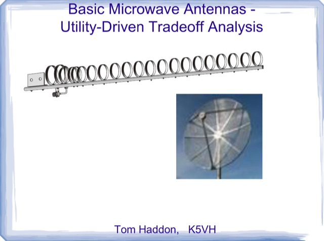 Utility-Driven Tradeoff Analysis, if you want to geto on the microwave bands , you will have to choose the proper antenna for your operating conditions. How to decide is not always easy, and you may also decide to build your own antenna.