Search results
Query: final
Links: 72 | Categories: 0
-
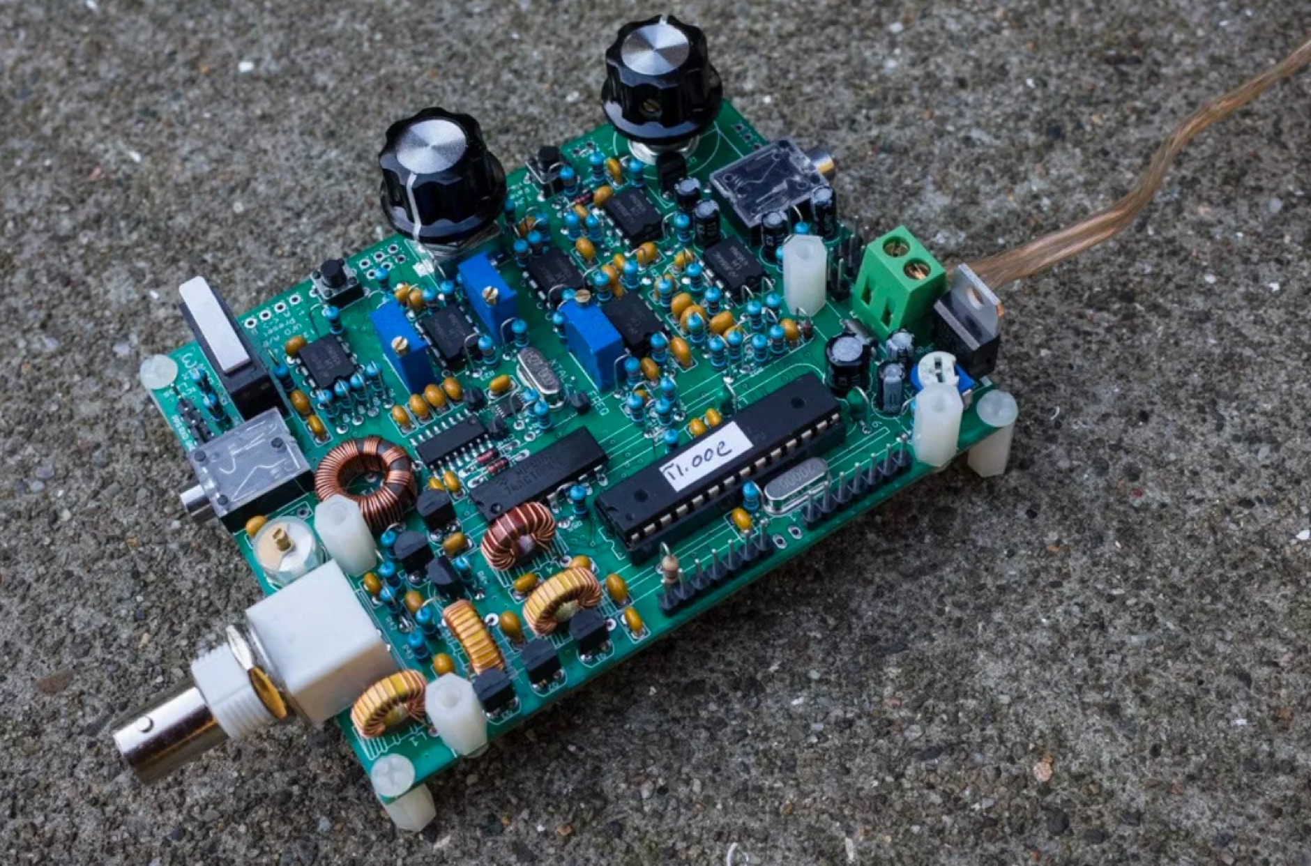
 Circuit diagram and discription of 7 MHz Ham Radio SSB Transceiver. Transceiver using two MC1496, 4.43 MHz Ladder filter, LM386, LM324 and IRF840 in final.
 -
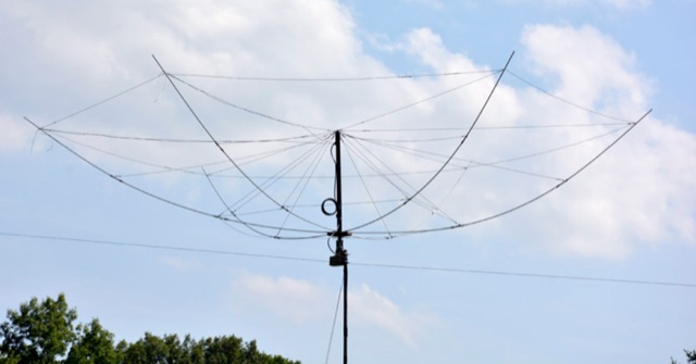
 Presents a practical design for a **crossed-dipole turnstile antenna** specifically engineered for 2-meter Amateur Radio Direction Finding (ARDF) events. The author, WB6RDV, details a robust, omnidirectional, horizontally-polarized antenna, addressing the international ARDF rules requiring such characteristics at a height of two to three meters above ground. This contrasts with the vertical polarization often used in Southern California, highlighting the design's adherence to specific event requirements. The electrical design employs a classic crossed-dipole with a 75-ohm phasing section, resulting in a slight impedance mismatch and an SWR of approximately 1.3:1 with a 50-ohm feedline. Construction utilizes readily available and inexpensive PVC plumbing components and 1/8-inch bronze welding rod for elements. The guide provides step-by-step instructions for mechanical assembly, including drilling element holes at precise 90-degree spacing and preparing the RG-179 matching section. WB6RDV shares insights from his own build experience, discussing the use of plated brass versus aluminum spacers for element attachment and the effectiveness of crimping as an alternative to soldering. The document also covers final assembly, including the integration of ferrite beads as a choke balun and options for weatherproofing and alternative mounting configurations, emphasizing the adaptability of the design for other VHF bands through scaling.
 -
 This circuit is unique in that it uses a power mosfet as a final rather than a conventional bipolar transistor.
 -
 The 30/40 meter **vertical antenna** project by IK4DCS details the construction of a shortened, self-supporting design, reaching a total length of 5 meters. The antenna incorporates a linear loading section and a coaxial cable trap for 30 meters, based on the "Antenne Volume 2°" text by Nerio Neri (page 223). The design uses six radials, three for each band, positioned at approximately 90° inclination and at least one meter above the roof or ground, connected via a 1:1 balun at the feed point. Mechanical construction utilizes aluminum tubing, with a 2.30-meter primary radiator section (30 mm diameter) joined to a second part using a Teflon insert and a PVC sleeve for rigidity. The linear load, approximately 3.70 meters long, accounts for a 30% physical shortening of the quarter-wave element. A capacitive load, made from three 50 cm radials, is integrated into the 40-meter top section for fine-tuning. Final adjustments involved radial inclination for 40 meters, as initial testing showed increased SWR and interference on 30 meters due to nearby resonant structures. The author emphasizes the importance of clear space for optimal performance and provides drawings and photos to clarify the build process.
 -
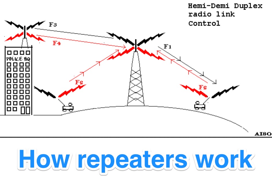 Illustrates the fundamental principles of radio repeater operation, detailing how different duplex configurations overcome signal limitations in varied terrains. It begins by contrasting _simplex_ communication, where all units share a single frequency, with more complex systems designed for extended range and specialized applications. The resource systematically presents each mode, from basic base station setups to advanced multi-frequency configurations. The content specifically covers hemi-duplex systems, often used in commercial dispatch, where the base station transmits on one frequency and mobiles on another, without rebroadcast. It then progresses to semi-duplex repeaters, the most common type in amateur radio, which automatically retransmit received signals on a different frequency. The explanation extends to demi-duplex and hemi-demi-duplex systems, which incorporate multiple control links for enhanced operational flexibility and secure communications, as seen in public safety applications. Finally, the resource clarifies full-duplex repeater systems, exemplified by cellular networks, where simultaneous two-way communication is achieved through distinct transmit and receive frequencies for each direction. The visual aids, including **9 distinct figures**, effectively demonstrate the signal paths and frequency assignments for each operational mode, providing a practical understanding of repeater architecture.
 -
 A rotary trapped-dipole for 17 and 20 meters, as described by IZ7ATH, presents a practical solution for multi-band HF operation. The author, Talino, recounts his experience building this antenna for IK7ZCQ, detailing the evolution from an initial concept involving a grounded-driven element and gamma-match to a direct-fed, non-grounded design. His pragmatic approach, adapting available materials, is evident throughout the construction narrative, particularly with the use of eight tapered aluminum pipes for the driven element. Construction specifics include precise measurements for the aluminum tubing, with diameters ranging from 30 mm down to 16 mm, and a critical note on reducing tip thickness for weight optimization. The _traps_, initially a concern, are fabricated using 8 turns of RG58 coax on a 27 mm support, tuned to resonate at 18.1 MHz using a dip-meter. Talino emphasizes sealing the traps with RF glue and PVC tape to prevent water ingress, a crucial step for longevity. Field test results, conducted on a 10-meter pole in a clear garden environment, showed an SWR of 1.2:1 on 17 meters and 1.5:1 at 14.200 MHz. While SWR varied slightly when installed at Mario's QTH due to nearby objects, the antenna's performance remained commendable. The final half-dipole length is 46 cm for the 18 MHz tips, and the total weight is under 6 kg, with potential for further reduction.
 -
 The BV6 50 MHz Yagis resource details the construction of two distinct Yagi antenna designs for the 6-meter band, specifically a 1-wavelength (1wl) model and a 2.1-wavelength (2.1wl) model. The 1wl Yagi, with a boom length of 5.850m, achieves a gain of **9.4 dBd**, while the 2.1wl Yagi, spanning 12.90m, boasts a gain of **11.9 dBd**. These designs adhere to a proven methodology for optimizing current slope and maintaining constant phase delay across parasitic elements, ensuring high gain per boom length and an _excellent pattern_. Both designs target a 50-ohm input impedance, facilitating straightforward feeding with a robust folded dipole. Final verification using NEC-II software confirmed the antennas' exceptional stacking capabilities, yielding stacking gains exceeding **5.8 dB** for a 2x2 array with minimal mutual detuning. The resource provides common mechanical data, including boom and element diameters, and specifies element lengths corrected for boom diameter. While the original _DUBUS Technik V_ publication contained incorrect element lengths, this resource provides the accurate dimensions for proper construction, emphasizing the use of readily available materials for cost-effective amateur radio deployment.
 -
 Constructing a linear focus parabolic antenna for WiFi operation involves precise metalwork, as detailed in this project. The author, AB9IL, shares a build that can be completed in a few hours, emphasizing the hands-on process of shaping and assembling metal components. This design aims to provide enhanced signal range for 2.4 GHz wireless networks, a common challenge in many ham shacks and home setups. The project outlines the practical steps required, from initial measurements to the final assembly, including cutting, bending, and bolting various metal parts. While specific gain figures are not provided, the parabolic design inherently offers significant _directional gain_ compared to omnidirectional antennas, making it suitable for point-to-point links or extending network coverage over distances. The construction process focuses on readily available materials and basic shop tools, aligning with the DIY spirit prevalent in amateur radio. This antenna project is presented as a straightforward build, requiring attention to detail in fabrication to achieve optimal performance.
 -
 W1ZY's 40 Meter MOXON is the product of 9 months of experimentation. The final array is reversible and constructed from No. 12 insulated wire fed through two RF current baluns
 -
 LogDDM, a freeware logging application, supports the tracking of over **100** different awards, including _DXCC_, WAZ, and WAS, directly within its interface. This software facilitates comprehensive log management for amateur radio operators, integrating functionalities such as a built-in callbook lookup, real-time packet cluster access, and direct rig control for various transceivers. It also offers robust import and export capabilities, primarily utilizing the ADIF format, which is essential for submitting logs to award sponsors or transferring data between different logging platforms. Developed by Giorgio, IV3DDM, the program is designed to streamline the logging process, allowing hams to efficiently record contacts and manage their QSL information. It provides a centralized hub for operational data, from initial QSO entry to final award application. Key features include detailed QSL management, support for multiple operating modes, and a user-friendly interface, making it a practical tool for daily operating and contest logging.
 -
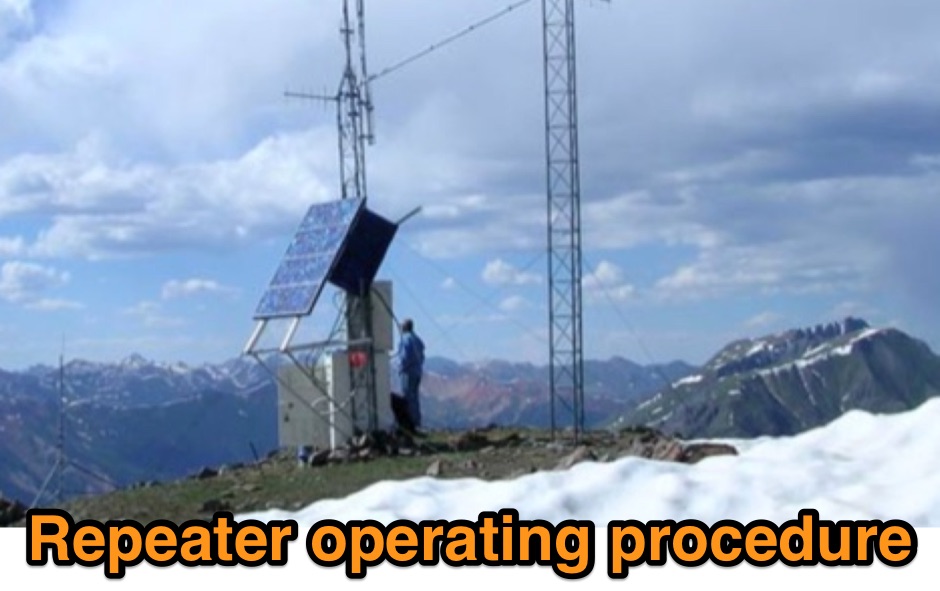 Outlines recommended operating procedures for amateur radio repeaters, detailing best practices for general on-air conduct. It emphasizes using simplex when possible, monitoring the frequency before transmitting, and maintaining concise, thoughtful transmissions to avoid monopolizing the repeater. The resource also stresses the importance of legal identification, such as the Canadian requirement at the beginning and end of a contact and every thirty minutes of operation. Furthermore, the article provides specific instructions for **autopatch** operation, including access codes and the necessity of brief calls, while cautioning against misuse for long-distance calls or commercial purposes. It highlights the financial support expected from regular users to maintain repeater infrastructure. Finally, the guide differentiates between permanently linked repeaters, which offer extended coverage, and **code access linked repeaters**, explaining the sequence of identification and code entry required to establish and terminate links for broader communication.
 -
 The QRP choke balun described utilizes a high permeability ferrite rod and RG-174 coax, aiming to present high impedance to common-mode currents across the HF spectrum. The construction involves winding as many turns of RG-174 as possible around the ferrite rod, then encapsulating the assembly with hot glue. This design prioritizes maximizing inductance to suppress unwanted shield currents, particularly in unbalanced antenna configurations. While the balun's effectiveness is subjectively reported as good, a potential design consideration involves the dielectric properties of the hot glue. This material could increase turn-to-turn capacitance, potentially reducing the balun's performance at higher HF frequencies, though this specific aspect has not been formally tested by the author, _AA5TB_. The project serves as an illustrative example of a practical, junk-box construction rather than a rigorously engineered solution. Photographs detail the evolution of the balun, from the initial winding process to its integration within a _B&W dipole center insulator_ and final camouflaged assembly.
 -
 This article describes a low-cost vector network analyzer that operates from 200 kHz to 100 MHz, and connects to a personal computer using a USB 1.1 interface By Tom McDermott, N5EG, and Karl Ireland
 -
 A VHF power amplifier made with two cheap RF transistors, 2N3924 as driver and a BFS22A for final stage, giving an unexpected output power of 7-8 watts maximum
 -
 The ZS6BKW antenna, a popular multiband wire antenna, offers improved band matching compared to the traditional G5RV. This construction guide details the process, beginning with specific dimensions: 13.11 meters (43 feet) for the 450-ohm ladder line and initial dipole arm lengths of approximately 14.8 meters each. It emphasizes the critical role of an _antenna analyzer_ for accurate tuning, particularly for determining the velocity factor of the ladder line and achieving a 1:1 impedance match. The article outlines the materials required, including a 1:1 current balun, 450-ohm window line, wire for the dipole arms, and a 50-ohm non-inductive resistor for testing. It provides a step-by-step procedure for cutting the ladder line to its electrical half-wavelength, explaining how to calculate the velocity factor using measured and free-space frequencies. For instance, a measured 50-ohm impedance at 12.54 MHz with a calculated free-space half-wavelength frequency of 11.44 MHz yields a velocity factor of 0.91. Final adjustments involve hoisting the antenna to its operational height and fine-tuning the dipole arm lengths to achieve optimal SWR, specifically targeting 14.200 MHz. The _ZS6BKW_ design is noted for its performance on 80m, 40m, 20m, 10m, and 6m, though it is not optimized for 15m operation. The author, _VK4MDX_, shares practical tips for durable construction using stainless steel wire and cable clamps.
 -
 Demonstrates the design principles and performance characteristics of **corner reflector antennas**, emphasizing their high gain and directional properties. It covers critical design factors such as the corner angle and the spacing between the radiating dipole and the reflector vertex. The resource explains how reducing the corner angle increases gain but lowers feed impedance, making matching more challenging. Practical angles of 90 degrees or 60 degrees are discussed, with 90 degrees offering easier impedance matching despite slightly lower gain. Details key design considerations, including reflector side length exceeding two wavelengths and reflector width greater than one wavelength for a half-wave radiator. It specifies reflector construction using wire netting, sheet metal, or parallel metal spines spaced less than 0.1 wavelength. The article provides a table with general dimensions for UHF and VHF bands, noting typical impedance values of 50 to 75 ohms and expected SWR of 1.7:1 on the lower band edge. Adjustable radiator-to-vertex spacing is highlighted as crucial for final tuning.
 -
 A homebrew dummy load is usually a combination of several parallel carbon resistors, in order to be able a final resistance of 50 Ohms.
 -
 The Collins TRC-75 autotune linear amplifier, owned by JF2SVU, is presented with a focus on its internal modifications. This QRO amplifier utilizes three 4CX250 tubes in parallel for its final stage, delivering 1 KW output power. Notably, the amplifier achieves full power with only 100 mW of RF input, a characteristic often associated with Collins designs. The original 400 Hz power supply has been converted for easier shack integration, and the entire RF and power supply sections have been rehoused into a compact, clean enclosure. The control unit, positioned above the amplifier, features three meters for individual vacuum tube IP monitoring and a multi-meter on the right. A dedicated 7 MHz receiver, recently completed, is also part of this integrated system. The autotune functionality means the main amplifier unit only requires connections for power, control, and coaxial cables, simplifying its operation. Key components like the 4CX250 tubes and NF capacitors are visible, along with the gearing mechanism for the final tank circuit. A timer and relay system manages high-voltage delay and cooling fan off-delay, although the cooling fan's airflow is noted as somewhat insufficient. A central volume control, which experienced a contact issue, is also highlighted.
 -
-
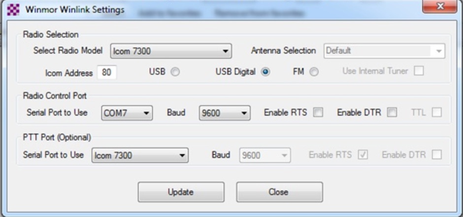 This tutorial provides step-by-step instructions for setting up the ICOM IC-7300 to work with WinLink and WinMor. The process begins with downloading the necessary USB driver from ICOM Japan, followed by configuring the radio settings through the menu. Key settings include selecting the correct output and data modes, as well as ensuring the USB serial function is properly set. Once the radio is connected to the PC via USB, the drivers will install automatically, allowing for seamless communication. After confirming the installation of the USB Audio CODEC and COM port, users are guided to download the RMS Client Software for WinLink. The tutorial emphasizes the importance of understanding the WinLink system and provides links to additional resources for setup. Finally, it details how to configure the WinMor modem settings, ensuring the ICOM IC-7300 is ready for effective digital communication. This guide is essential for operators looking to enhance their digital capabilities using the IC-7300.
 -
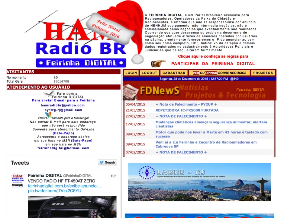 Presents a Brazilian online portal dedicated to **amateur radio**, **CB radio**, and shortwave listening (SWL) communities. The platform facilitates free classified advertisements for radio equipment, including HF, VHF, and UHF transceivers, antennas, and accessories. It also aggregates a substantial collection of technical articles from Brazilian amateur radio operators (e.g., PY2DJW, PY1LJ, PY1LL/4LC), covering topics such as CW training with RufzXP, balun importance, and radio wave characteristics. Furthermore, the resource provides extensive links to Brazilian ham radio sites, clubs, international organizations, and official ANATEL (Brazilian National Telecommunications Agency) documents regarding licensing, equipment homologation, and regulations. The portal features sections for user evaluations of transactions, a "Top Ten" list of most visited pages, and a calendar of past and upcoming ham radio events across Brazil, including "Feirinhas" (local swap meets) and "Encontros de Radioamadores" (hamfests). It also includes a directory of ham radio related businesses and services in Brazil, such as antenna manufacturers (Diex), QSL card printers (Arte Final), and repair technicians (PY2MOK). The site also offers propagation maps, DX cluster links (e.g., DX-SUMMIT), and satellite tracking tools, making it a central hub for Brazilian radio amateurs seeking to buy, sell, learn, or connect with the community.
 -
 A 200 kHz bandwidth digital transmission system for image transfer in the Amateur Service is under development, specifically targeting VHF allocations. John B. Stephensen, KD6OZH, leads this project under an FCC Special Temporary Authority (STA) valid until September 10, 2006, authorizing emissions up to 200 kHz bandwidth in the 50.3-50.8 MHz segment. Current regulations typically limit bandwidths to 20 kHz on VHF amateur bands, making this STA crucial for testing wideband digital modes. The modem, a modified **OFDM** (Orthogonal Frequency Division Multiplexed) unit, was initially tested on the 70-cm band. It splits a high-rate data stream into multiple low-rate subcarriers to mitigate multipath echoes. The system uses a DCP-1 card with a Xilinx XC3S400 FPGA and Oki Semiconductor ML67Q5003 microcontroller. The transmitter, located at 36d 46m 30s N, 119d 46m 22s W, generates 150 WPEP into an 8 dBi gain vertical antenna, while the mobile receiver uses a Ham-stick. Three data formats for 50, 100, and 200 kHz channels are being tested, with encoded data rates of 96, 192, and 384 kbps. Verilog code for the VHF OFDM modem is 95% simulated, with modifications from the UHF version including increased filter coefficient precision and a change from Ungerboeck **TCM** to BICM for improved performance over fading paths. Final tests will involve one-way over-the-air measurements of bit error rates and coverage area.
 -
 The **TransWorld Antennas TW2010 Traveler HF Portable Vertical Antenna** assembly video provides a visual walkthrough for deploying this popular portable HF antenna. It details the step-by-step process, from unpacking components to final setup, which is crucial for operators preparing for field day operations or DXpeditions. The video focuses on practical aspects, showing how to connect the various elements and secure the antenna for optimal performance. Operators often seek clear assembly instructions for portable antennas like the TW2010 to ensure quick and correct deployment in diverse environments. This visual aid helps clarify potential ambiguities found in written manuals, illustrating the proper handling of the antenna's radial system and telescopic elements. The video serves as a valuable resource for those aiming to achieve efficient operation with the **TW2010 Traveler** in a portable setting. Understanding the assembly sequence can significantly reduce setup time and prevent common errors encountered during initial deployments.
 -
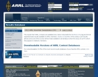 The ARRL Contest Results Database serves as a centralized repository for official scores and detailed breakdowns from numerous ARRL-sanctioned operating events. This resource typically features comprehensive listings of participants, their submitted logs, and final standings across different categories, modes, and bands. It allows hams to review their performance, compare results with other operators, and analyze contest trends over time, providing valuable insights into competitive amateur radio. Historically, the database has showcased the efforts of thousands of contesters, from single-operator entries to multi-operator, multi-transmitter stations. While the current status indicates scores are not immediately available, the database's primary function is to archive and present the outcomes of events like the ARRL DX Contest, Sweepstakes, and Field Day. This historical data is crucial for tracking individual progress, identifying top performers, and understanding the competitive landscape within the amateur radio community.
 -
 KB6NU end-fed, half-wave antenna article and project
 -
 K9EID 75W power amplifier for the six meters
 -
 Announces the retirement of Brand Electronics, a manufacturer specializing in **power meters** and various ham radio accessories, effective 2025. The company has served the amateur radio community for over 35 years, providing equipment for station setup and operation. The product line historically included accessories compatible with major transceivers from Icom, Yaesu, and Kenwood, alongside components and technical references for homebrew projects. Their offerings supported accurate RF power measurement, crucial for optimizing antenna systems and ensuring legal limit compliance. This notice serves as a final update regarding the company's operational status, marking the cessation of manufacturing and sales activities. The site provides no further details on product support or inventory liquidation.
 -
 On March 27, 2017, the FCC adopted final rules for the USA 630-meter band, detailed in Report and Order FCC 17-33, which required PLC coordination with the Utilities Telecom Council before amateur operations could commence. This resource documents the WD2XSH experimental group's activities, including authorized stations, band plans, and frequency assignments within the 465-515 KHz range, with many stations operating between 495-499 KHz and 501-510 KHz. The site also highlights the WRC-12 decision on February 14, 2012, which granted a new **7-kilohertz-wide** secondary allocation between _472-479 kHz_ for the Amateur Radio Service worldwide. The group's efforts included operating with a maximum ERP of **20 Watts** across 45 stations in the continental USA, Alaska, and Hawaii, using emission modes such as CW, PSK-31, FSK-31, and MSK-31. The site provides links to download FCC 17-33 in PDF and DOCx formats, and offers a station location map, a list of stations by callsign and frequency, and an archive of news updates. Reception reports for any 600-meter station are encouraged to help the amateur radio community understand propagation and repeatability on this challenging band.
 -
 The _Alessandro Volta RTTY Contest_ is an annual digital mode competition focusing on Radioteletype (RTTY) operation, challenging participants to make contacts across various HF bands. This event typically occurs in January, drawing a global field of operators aiming to maximize their QSO count and multiplier accumulation. The contest emphasizes accurate exchange of signal reports and serial numbers, with specific rules governing single operator, multi-operator, and SWL categories. Participants utilize software like _N1MM Logger+_ or _WriteLog_ to manage their logs and generate Cabrillo files for submission. Scoring is based on points per QSO, multiplied by unique DXCC entities and Italian provinces worked on each band. The contest encourages both seasoned RTTY contesters and those new to digital modes to engage in competitive HF activity, promoting skill development in digital communication. Final results and logs are typically published on the contest website, showcasing top performers and providing detailed breakdowns of scores.
 -
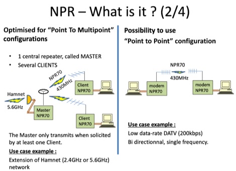 A Quick start guide to NPR New Packet Radio on 70 cm band by the NPR author Guillaume F4HDK. This presentation introducte basic concepts of this niew digital protocol, and guide the user to the first modem configuration both of client and master modems. Includes a final recap of commands.
 -
 Constructing a high-performance RF spectrum analyzer up to 1000 MHz requires careful attention to component selection, shielding, and circuit isolation. This resource details a project that improves upon the _Spectrum Analyzer for the Radio Amateur_ design by Wes Hayward (W7ZOI) and Terry White (K7TAU), incorporating ideas from Scotty Sprowls' project, particularly his 1013.3 MHz IF bandpass cavity filter. The analyzer utilizes a Mini-Circuits SRA-11 mixer with a sweeping local oscillator from 1013 to 2013 MHz, feeding into a 4-pole copper pipe cavity filter. The design employs a second SRA-11 mixer with a fixed 1024 MHz LO to produce a 10.7 MHz final IF. This signal then passes through narrowband resolution filters and is processed by Analog Devices AD603 and AD8307 ICs for IF amplification and logarithmic detection, driving an oscilloscope in X/Y mode. The project emphasizes modular construction, using salvaged components and double-sided FR4 material for PCBs, with critical notes on minimizing spurious images through effective shielding and proper voltage regulation for each module. Key components include a Z-Communications V585ME48 VCO for the first LO and a Z-Comm V583ME01 VCO controlled by a Motorola MC145151 PLL for the second LO. An optional Hittite HMC307 step attenuator and K&L 5L121-1000/T5000-O/O low-pass filter manage RF input. Tuning procedures for the 10.7 MHz IF resolution filter are also detailed, showing before-and-after spectrum views.
 -
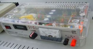 A linear regulated power supply 2A, 20 V designed mainly to get used to soldering and have something usefull as final result.
 -
 RF amplifier products from NP Technologies, Inc. encompass a wide array of specialized designs, including highly linear Class A broadband amplifiers, crucial for maintaining signal integrity across various frequencies. Their portfolio also features cell band amplifiers, specifically engineered for cellular communication infrastructure, and pulse amplifiers, which are vital in applications requiring high-power, short-duration signal bursts. The company's manufacturing capabilities extend to AM and FM broadcast amplifiers, supporting radio transmission systems, and military VHF amplifiers, designed to meet rigorous defense specifications for robust and reliable communications. NP Technologies, Inc. emphasizes comprehensive development, design, manufacturing, and testing processes for all its RF amplifier offerings. This integrated approach ensures that each product, from initial concept to final deployment, adheres to stringent performance and reliability standards. The company's expertise in these areas allows for the creation of custom solutions tailored to specific client requirements, addressing complex RF challenges in diverse operational environments. Their product range demonstrates a commitment to serving multiple sectors, including commercial broadcasting, telecommunications, and defense. The focus on specialized amplifier types underscores their technical depth in RF engineering.
 -
 A DIY aluminium push up mast project. The final mast includes 7 aluminium tubes with 6 cable clamps
 -
 Developing operational amateur radio equipment for the 134 GHz band presents significant technical challenges, particularly in frequency generation and stability. This resource details the construction of a 134 GHz system, outlining its architecture with separate transmit (Tx) and receive (Rx) modules, each employing a local oscillator (LO) and RF head units. The system utilizes a dual Flann 50 GHz lens-type horn antenna configuration for optimal signal coupling. The transmit path incorporates an LMX2541 synthesizer chip operating at approximately 2.8 GHz, referenced by a 10 MHz double-oven Morion OCXO for exceptional stability. This signal is multiplied through a series of stages (X4, then X2) to generate a 22.4 GHz signal, which subsequently drives a dual series diode multiplier to produce the final X6 signal for 134 GHz operation. The receive side features an anti-parallel diode mixer coupled to a 144 MHz transceiver via a preamplifier, ensuring effective downconversion. Operational mode is CW, achieved by keying a multiplier stage. The project includes images of the Tx and Rx head units and describes a successful 3.5 km test with G8ACE, demonstrating stable signal tones due to PLLs locked to OCXOs at both ends, confirming the system's robust performance.
 -
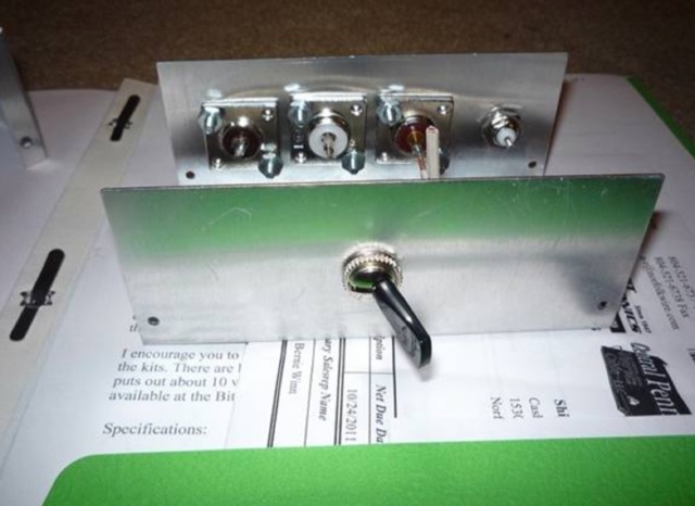 An home made antenna switch with a Dummy Load selector. If you forget the radio is connected to the open or grounded side of the switch and you try to transmit, it is very easy to damage the finals of your transceiver.
 -
 The PI6ATV repeater, operating on 10.475 MHz, serves the amateur television community by providing both analog and digital DVB-S2 services. Recent updates include user-adjustable Symbol Rate settings via Webcontrol, allowing operators to optimize their digital ATV transmissions for various conditions. This functionality, implemented on December 13, 2022, enables dynamic configuration of the digital stream. Significant technical milestones include the return of the analog ATV transmitter on 10.475 MHz, featuring a newly constructed liquid-cooled final amplifier by Edwin PD2EBH. This restoration on September 6, 2020, followed an 18-month hiatus, ensuring continued support for traditional analog ATV enthusiasts. The repeater's transition to DVB-S2 modulation, initiated on December 20, 2018, addressed capacity limitations of the previous DVB-S setup. This change from 20 MS/s with FEC 3/4 to DVB-S2 allowed for more efficient data handling, accommodating multiple channels within the available bandwidth and enhancing the overall digital ATV experience.
 -
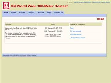 Presents the official results for the _CQ World Wide 160-Meter Contest_, a premier event for Top Band enthusiasts. The resource details final scores for both CW and SSB segments, offering links to comprehensive articles, plaque winner lists, and club score breakdowns. It also includes access to score databases for individual modes and years, along with "Soapbox/QRM Comments" from participants, providing insights into operating conditions and experiences. This archive spans results from 2010 through 2025, with a forward-looking note regarding the 2026 SSB contest date adjustment due to a conflict with the _ARRL DX CW Contest_. The site provides specific links for each year, allowing operators to review detailed outcomes, including top scores, errata, and all-time records, such as the _SX5R_ 2017 SSB performance. The structured presentation facilitates easy navigation through historical contest data.
 -
 This resource provides a historical analysis of amateur radio call sign assignment policies in the United States, detailing regulatory shifts from the Department of Commerce to the Federal Radio Commission (FRC) and subsequently the Federal Communications Commission (FCC). It documents the evolution of call sign issuance, from early reissuance practices in the 1920s to the implementation of the Group Call Sign Assignment System on March 24, 1978. This system categorized call signs (e.g., 1x2, 2x1, 1x3, 2x3 formats) into groups A, B, C, and D, correlating with license classes such as Extra, Advanced, General, and Novice, and specifying prefixes for contiguous U.S. and territorial areas (e.g., _AH_, _KP_, _KL_). The document further details the legislative process leading to the modern Vanity Call Sign program, initiated by a petition in June 1990 and formalized by the Omnibus Budget Reconciliation Act of August 10, 1993. It outlines the FCC's adoption of final rules on December 23, 1994, and the subsequent fee structure, with the first vanity call sign issued on May 31, 1996, at a cost of **$30.00** for a ten-year term. The ARRL's proposed "starting gates" implementation strategy is also described, which phased in eligibility for vanity call signs based on license class and prior holder status. DXZone Focus: Historical Document | Regulatory Analysis | Call Sign Formats | Fee Structure
 -
 The QCX 5W CW Transceiver From QRP Labs, a detailed article describing from the unboxing of the component to the final assembly of the CW QRP Transceiver
 -
 The DIY 137 MHz WX SAT V-dipole antenna project details the construction of a specialized antenna for receiving weather satellite transmissions. It provides specific dimensions for the dipole elements, designed for optimal reception around the 137 MHz band, which is commonly used by NOAA and Meteor weather satellites. The resource outlines the materials required, such as aluminum tubing for elements and PVC for the support structure, along with the necessary coaxial cable and connectors. The article presents a clear, step-by-step assembly process, including how to form the V-shape and connect the feedline. It emphasizes practical considerations for mounting and weatherproofing the antenna for outdoor deployment. The design focuses on simplicity and effectiveness for amateur radio operators interested in satellite imagery. Key aspects include the precise angle of the V-dipole and the lengths of the radiating elements, which are critical for achieving the desired circular polarization response for satellite signals. The resource includes photographic documentation of the construction phases and the final mounted antenna.
 -
 Documents S21RC's construction of an impedance transformer harness for a VHF/UHF cross yagi, utilizing 20m of _RG179_ cable. Details the creation of a DIY RF sampler with a -50dB sampling output, primarily for measuring HF radio PA section output with a Spectrum Analyzer, also applicable for _Pure Signal_ transmission. Chronicles the deployment of a 200m long beverage antenna for the _S21DX IOTA_ operation in 2022, positioned 2m above ground. Discusses the construction of a 3-element short beam for 10m to replace a previous 2-element antenna, with assistance from S21DW. Provides guidance on operating cheap _PA-70_ and _PA-100_ type Chinese SSPAs using IRF530 MOSFETs, emphasizing the necessity of a final LPF. Outlines the design and construction of a fully isolated interface for radio-to-computer connections, supporting various digital modes with isolated ground, audio transformers for IN/OUT, optical isolation for CAT/CIV, and isolated PTT/COS lines. Includes a log of software updates, such as the _HMI/TFT for NX8048K070_ and _2.1.14 Lite_ release with bug fixes for PEP hold and gradual watt decay.
 -
 The Ontario QSO Party (OQP), an annual event, takes place on the third full weekend of April, specifically from 1800Z April 18 to 0300Z April 19, 2026, and 1200Z to 2000Z April 19, 2026. This **QSO party** encourages stations outside Ontario to contact as many Ontario amateur radio stations as possible, while Ontario stations work both in-province and worldwide. Key rule changes for 2026 include phone QSOs now counting equally with **CW** QSOs (2 points), the introduction of VE3RHQ as a bonus station, a 250m county line proximity definition, and a new Fixed County Line Category, alongside an adjustment of contest times. Established in 1998 by Bob Chandler VE3SRE, the OQP has been managed by Contest Club Ontario (CCO) since 2006. The event contributes to the State QSO Party Challenge, offering various award categories and maintaining records of past performance. Participants can submit activation plans, review Ontario multipliers, and access county maps. Final results and certificate winners are published, and a dedicated groups.io discussion group facilitates community interaction and support for logging software.
 -
 With an eye to the final cost I have built a good 20 meter monoband Hex Beam antenna.
 -
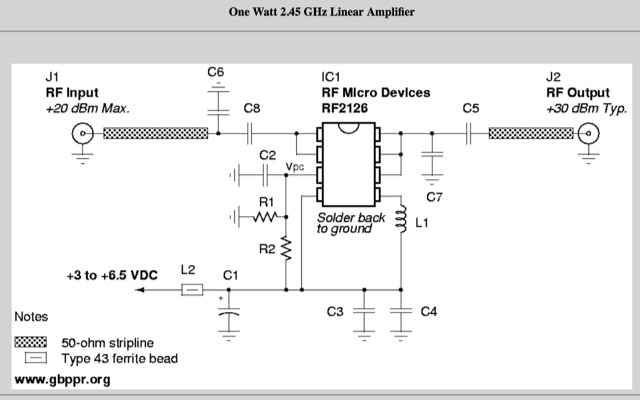 This will show you how to add a RF power amplifier to your Proxim Symphony for under $50. The cost is reduced by using the existing components on the Symphony, such as the PIN diode switch, and just inserting a higher power final amplifier. Increase the RF output power of your wireless network card to 1 Watt.
 -
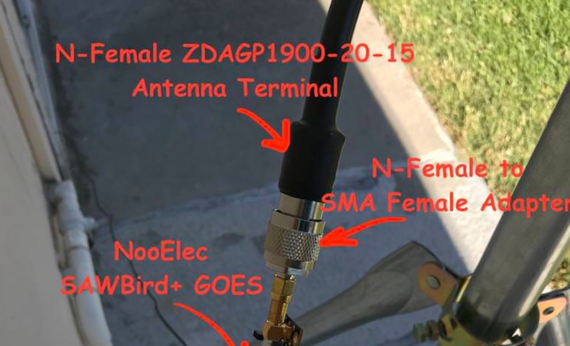 Receiving **GOES-16** and **GOES-17** weather satellite imagery requires a specific hardware and software configuration, detailed in this practical guide. The author outlines the necessary components, including a Raspberry Pi, an RTL-SDR dongle, a suitable LNA with SAW filter for 1.69 GHz, and a parabolic grid antenna. This setup enables direct reception of high-resolution weather data, a fascinating aspect of amateur radio satellite operations. The installation process begins with preparing the Raspberry Pi, followed by updating the system and installing essential dependencies like `git`, `build-essential`, and `cmake`. A critical step involves compiling and installing `librtlsdr` from source, ensuring proper driver setup and blacklisting conflicting DVB drivers. The guide then walks through testing the RTL-SDR dongle to confirm device recognition and troubleshoot common issues like USB power or driver installation problems. Finally, the instructions cover cloning and building `goestools`, a software suite essential for processing the satellite signals. This compilation, while time-consuming on a Raspberry Pi, is crucial for decoding the raw data into usable imagery. The guide concludes with the initial steps for creating the `goesrecv.conf` configuration file, preparing the system for active satellite reception.
 -
 The video showcases the setup of a 300 MHz oscillator, a 100W radiofrequency amplifier, and a dipole antenna for transmitting radio waves, leading to the fluorescence of a nearby light bulb. It demonstrates the presence of standing waves on the dipole antenna and how intensity varies along its length. Additionally, the usage of a copper pipe as a receiving antenna is explored, showing changes in intensity depending on alignment and proximity to the transmitter. Finally, a B field antenna sensitive to magnetic fields is introduced, revealing brightness variations in different orientations. The video offers insightful observations on radio wave transmission and reception phenomena.
 -
 A homemade MFSK16 APRS HF tracker, worked pretty well for 1.5W on a Lipo supply with only 2 of the 3 BS170 FETs in the final
 -
 Building an End-Fed Half-Wave (EFHW) antenna from a kit, as detailed by Frank Bontenbal, PA2DKW, with process photos by Bob Inderbitzen, NQ1R, offers a practical approach for hams. This specific kit, a collaboration between ARRL and HF Kits, targets 10, 15, 20, and 40 meters, making it a versatile option for HF operations. Unlike a center-fed dipole, the EFHW is a half-wavelength antenna fed at one end, which simplifies deployment, particularly for portable use. The construction guide meticulously outlines the assembly of the 49:1 impedance matching network, crucial for transforming the antenna's high impedance (around 2,500 Ohms) to a transceiver-friendly 50 Ohms. Steps include preparing the enclosure by drilling holes for the coaxial connector and antenna connections, followed by the precise winding of enameled copper wire onto a toroid to create the transformer. The guide emphasizes careful insulation removal and soldering for reliable connections. Final assembly involves integrating a 100 pF capacitor for higher band compensation, soldering the transformer's primary and secondary sides, and conducting SWR tests with a 2K7 resistor or a half-wavelength wire. The document also provides examples of wire lengths for different bands, such as 16 feet for 10 meters or 66 feet for 40 meters, demonstrating the transformer's adaptability for various half-wavelength configurations.
 -
 This practical, hands-on article offers a valuable journey through balun construction for portable antenna systems. The author skillfully navigates from theoretical debates to practical implementation, providing a well-documented DIY process using RG316 micro coax and an FT114-43 toroid core. The step-by-step instructions, complemented by photographs, make this complex technical project accessible to hobbyists. Particularly impressive is the author's focus on lightweight design (just 173 grams) for SOTA field operations. While the final antenna requires minor tuning adjustments, the successful field test during the Pirate Contest demonstrates the effectiveness of this approach. An excellent resource that transforms theory into practical application for ham radio operators.