Search results
Query: front
Links: 106 | Categories: 3
-
 A modified 20 meter double zepp wire Operating Bands: 40 thru 10 meters (with tuner), basic construction and performance information.
 -
 Cubic quad antennas are renowned for their high gain, excellent front-to-back ratios, and low angles of radiation, making them a popular choice among amateur radio operators. This resource provides detailed designs for constructing cubic quads optimized for 2, 6, 10, 12, and 15 meter bands. The lightweight structure can be easily built using fiberglass tubes and central hubs, allowing for portability and ease of assembly. The article discusses the specific dimensions and configurations required for both HF and VHF applications, emphasizing the importance of proper spreader lengths and boom dimensions. It also highlights the challenges of assembling larger cubic quads in limited spaces, offering practical solutions for hams with smaller backyards. With a focus on multi-band operation, this guide serves as a valuable resource for both novice and experienced operators looking to enhance their antenna systems.
 -
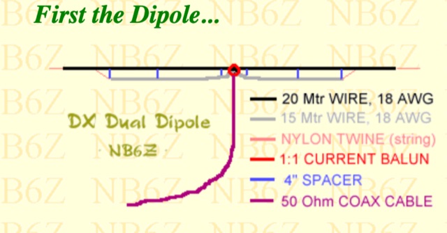 Two dipoles fed from the same coaxial line by n6bz for 20 and 15 meters
 -
 The Cubical Quad antenna is a popular choice among amateur radio operators due to its robust design and excellent performance characteristics. This resource provides essential scaling formulas that help determine the lengths of the antenna elements and the necessary gamma match values for various frequencies. The design is adaptable, allowing operators to optimize for gain or front-to-back ratio by adjusting the spacing between elements. The accompanying Excel files facilitate precise calculations, making it easier for both beginners and experienced hams to construct their own Cubical Quad antennas. In addition to the design formulas, the resource includes practical insights from the author, who has successfully built and utilized these antennas in various field events. The document outlines the tuning process for achieving minimum VSWR, ensuring optimal performance. With detailed illustrations and performance data, this guide serves as a comprehensive reference for anyone looking to delve into Cubical Quad antenna construction and optimization, enhancing their amateur radio experience.
 -
 SysLabs RadioControl is a software platform for radio device control and application development. It operates on _Windows_ versions from Windows 95 and Windows NT 4.0 through _Windows 11_. The software is available in Lite, Standard, and Professional editions, each including Frontpanel for direct radio control, a Frequency Database for management, and a Memory File for channel operations. Features include frequency identification, memory scanning, and graphical spectrum views with bitmap export capability. The Professional Edition supports multi-device control and utilizes radio device-internal scanners, achieving scan rates of **40-60 steps per second** compared to the RadioControl-internal scanner's **10-20 steps per second**. Supported devices for internal scanning include AOR AR-5000, AR-8200, AR-8600, AR-ONE, R&S EB200, and various Icom receivers and transceivers. RadioControl supports older devices such as ICOM IC-R71, IC-R7000, IC-706, IC-735, YAESU FRG-8800, and FRG-9600, extending their control capabilities. The platform offers APIs for integration and supports import/export with formats from VisualRadio, SCANcontrol, shoc Radio Manager, WiNRADiO, AOR ACEPAC-3A, as well as generic Text, CSV, and HTML. DXZone Focus: Radio Control | Windows | Frequency Management | API
 -
 Galaxy DX 47HP and DX 99V2 models are highlighted, showcasing the manufacturer's current offerings in both amateur and Citizens Band radio transceivers. The site details several amateur models, including the DX 29HP, DX 44HP, DX 55HP, DX 98VHP, DX 33HP2, and DX 94HP, catering to different operational needs and power levels. For CB operators, a range of models like the DX 2547, DX 979, and DX 929 are presented, with specific features such as _StarLite_ front panel lighting for low-light conditions, as seen on the DX 929 and DX 979. The DX 979 is noted for its compact form factor and SSB capability, making it suitable for installations where space is a constraint. Conversely, larger models like the DX 939, DX 949, and DX 959 are available for those with more room, offering features such as blue lighting and integrated frequency counters. The DX 939, for instance, combines aesthetic appeal with functional design, providing clear readouts and robust audio performance. A downloadable CB radio shopping guide is also offered, enabling users to compare Galaxy's product specifications against other radios on the market, facilitating informed purchasing decisions.
 -
 Examines the operational differences between **quad** and **Yagi** antenna designs, focusing on their respective performance characteristics for amateur radio applications. The document highlights key metrics such as forward gain, front-to-back ratio, and bandwidth, which are crucial for effective DXing and contesting. It discusses how element configuration, boom length, and material choices impact the efficiency and radiation patterns of each antenna type across various HF bands. Practical considerations for antenna builders are addressed, including structural integrity, wind loading, and overall weight, particularly when using fiberglass spreaders for quads. The resource also covers precipitation static reduction in quads due to their closed-loop design and their ability to operate efficiently at lower elevations compared to Yagis. It provides insights into dual-polarization feed systems for quads, offering independent vertical and horizontal feed points for enhanced operational flexibility.
 -
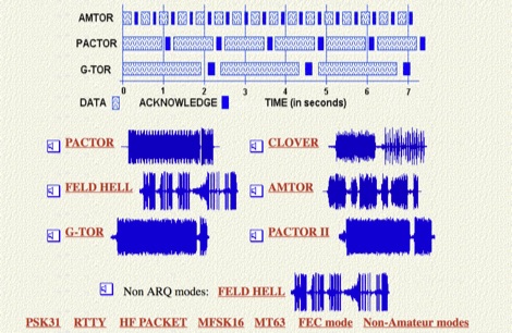 A complete overview of modern digital HF radio operating modes: PACTOR AMTOR GTOR CLOVER RTTY PSK31 HELLSCHREIBER PACKET MT63 MFSK16 THROB.
 -
-
 The project details modifications to an ARK-40 QRP CW transceiver kit, specifically replacing its original thumbwheel frequency selectors with a **BASIC STAMP BS-II microcontroller** and an optical shaft encoder. The redesigned control circuitry outputs a BCD code to the ARK-40's synthesizer, enabling more convenient knob-type tuning. This modification significantly alters the user interface, moving from discrete frequency selection to continuous tuning. Operating frequency is presented on an LCD readout, offering two distinct display modes: a "bandspread dial" mode that simulates an analog dial scrolling across the display in 1 kHz increments, and a conventional digital readout with 100 Hz resolution. Pushing the main tuning knob toggles between these modes, providing both rapid band traversal and fine-tuning capabilities. The software for the BASIC Stamp is written in P-Basic, addressing the challenge of accurate analog dial simulation. Physical modifications include fabricating a custom PC Board for the STAMP, mounting it with an L-bracket to the optical encoder, and creating a new front panel. The front-mounted speaker was relocated to accommodate the new tuning knob and display, transforming the **ARK-40 transceiver** into a more user-friendly rig with its built-in CW keyer and 5 watts of power.
 -
 Demonstrates the construction and on-air performance of the _NB6Zep_ antenna, a modified 20-meter Extended Double Zepp design optimized for multi-band operation from 40 through 10 meters. The resource covers basic design principles, including dimensions of 66 feet horizontal and 5 feet vertical elements, and specifies open ladder line or TV twin lead for the transmission line. It details material selection for low-cost wire antenna construction, such as 18 AWG wire for the legs and ceramic or plastic insulators, along with practical tips for soldering connections and insulating against moisture. The author, NB6Z, shares insights from extensive _EZNEC_ modeling to optimize the antenna's total length for a 40-meter half-wave dipole footprint and feed line length for direct tuner connection. The article presents field results, including successful _PSK31_ contacts from Oregon to the East Coast on 40 and 30 meters with 50 watts, even at a low height of 6 feet. It provides detailed performance characteristics for each band, noting the _NB6Zep_'s highest gain (over 3 dB) and sharp, medium-angle lobes on 20 meters, which yielded strong DX reports to locations like Korea, Japan, and Argentina. For 17 and 15 meters, it describes a butterfly-like pattern with broad lobes, while 12 and 10 meters exhibit narrow, directional lobes in an "X" configuration. The author also shares personal experiences operating successfully for over a decade in an antenna-restricted environment using the NB6Zep and other stealth wire antennas.
 -
 The PSK31 philosophy, tips and tricks, sound files, how to get started, sound card setup and tips.
 -
 The page provides detailed information about the construction of a full-size 160M 3 element beam antenna and an 80M 5 element beam antenna on a 330ft tower. It includes specifics about the tower height, types of antennas, elements, gain, take off angles, front-to-back ratio, operating frequencies, weight, and dimensions of the beams. The content is aimed at amateur radio operators interested in building high-performance antennas for the 160M and 80M bands. This Antenna is now been destroyed and is no more operational.
 -
 Catalogs a diverse array of Software Defined Radio (SDR) projects and realizations, systematically classified by their sampling methodologies and underlying hardware architectures. The resource delineates projects into categories such as those utilizing soundcard sampling of traditional transceiver audio outputs (Type Ia), mono soundcard sampling of intermediate frequencies (Type R1x-x-xx), stereo soundcard sampling of I/Q IFs (Type Q1x-x-xx), dedicated stereo audio ADC sampling of I/Q IFs (Type Q2x-x-xx), direct antenna RF signal sampling with off-the-shelf acquisition boards (Type R3x-x-xx), dedicated RF ADC sampling of analog IFs (Type R2x-x-xx), dedicated RF ADC sampling of direct antenna RF signals with ASIC-based processing (Type R4x-A-xx), FPGA-based processing (Type R4x-F-xx), and specialized IF chipsets combining ADC and DDC functions (Type Dxx-S-xx). Each entry provides a brief description, often including pricing, availability of source code, and specific hardware components like ADCs, DACs, DDS, and FPGAs. The compilation presents various practical applications, from PSK31 and Packet radio implementations to adaptations of the DRM standard for amateur radio bandwidths, such as Hamdream and WinDRM. It features specific hardware designs like the SoftRock-40 for the 40-meter band, the Firefly SDR for 30m and 40m, and more complex systems like the Quicksilver QS1R, which employs a 16-bit 130 Msamples/s ADC and an Altera Cyclone III FPGA. The resource also lists sample processing software, RF front-end designs, and academic/commercial SDR initiatives, offering insights into different approaches for I/Q conversion and digital signal processing in SDR systems.
 -
 Also known as the Backpacker's Delight Antenna. This Folding J Pole Antenna is the original design of Mike Heiler KA0ZLG and was featured on the Front Cover of the March 2005 QST Magazine.
 -

-
 Online Catalog & storefront (NJ) sales of amateur radio & related items.
 -
 buy and sell a diverse inventory of Navy, Army, USMC, Air Force, Coast Guard and home front related items from WWI through Vietnam.
 -
 Freeware antenna software that lets you see what the polar diagram of your rotatable beam actually looks like where it is operating. With PolarPlot you can measure the polar diagram of the antenna and check for abnormalities - compare plots taken before and after changes to the design or location - check the -3dB beamwidth - look at the front to back ratio - see the size and position of the sidelobes.
 -
 On 23cm the best way to obtain a good RX-sensitivity is to use a GaAs-FET in the front-end, since these devices show very low noise figures.
 -
 The EF0604S is a compact 4 elements yagi antenna plan for six meters band featuring 8.77 dBi gain and a front back gain of 17.89 dB. Article includes elements dimensions and spacing, along to pictures of some homebrewed examples.
 -
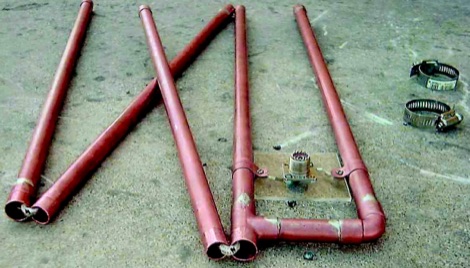
 The document details the optimization and construction of the _Maria Maluca_ antenna, a compact 6-band (20m-6m) directional beam. It presents a comparative analysis of shortwave antenna principles, highlighting the efficiency gains achieved by using an open feeder line and tuner as a resonant unit, contrasting this with the losses associated with traps or capacitive loads in multiband antennas. The resource specifically revisits an older South American 2-element design for 10, 15, and 20 meters, applying modern NEC-based software to develop a six-band version. Performance data is meticulously tabulated, showing impedance, free space gain, gain at 12m height, elevation angle, and front-to-back (F/B) ratio for each band from 20m through 6m. For instance, on 15m, the antenna achieves 5.1 dBd free space gain and 13.72 dB F/B ratio. The construction section provides practical guidance on element assembly using aluminum pipes and hose clamps, detailing the use of a heavy-duty glass fiber reinforced polyamide rod for electrical separation and bending strength. It also specifies the use of 450-ohm _Wireman_ line CQ 552 for the transmission line. The document includes diagrams for rod fixing, an air-wound balun, and a vertical elevation diagram for the 15m band, illustrating its DX qualification. It also discusses the antenna's suitability for portable and expedition operations, noting its compact transport dimensions (max 1.50m length, 12 lb weight) and quick assembly time (under 15 minutes). The author, Dipl.Ing. Helmut Oeller, DC6NY, is identified as a source for material kits.
 -
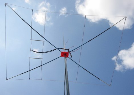
 The Moxon Rectangle is growing in popularity as a compact 2-element array that approaches a full-size 2-element in gain but with a far superior front-to-back ratio and a direct match for the standard 50-Ohm coaxial cable.
 -
 Presents a comprehensive guide for constructing a broadband Hex Beam antenna, a popular directional array for HF operation. This design offers a compact footprint and excellent gain characteristics, making it suitable for limited space installations while providing significant performance advantages over omnidirectional antennas. The resource details the specific dimensions for a five-band Hex Beam covering 20, 17, 15, 12, 10, and 6 meters, emphasizing the critical element spacing and wire lengths required for proper resonance and pattern. It outlines the construction of the center post, spreaders, and wire elements, along with the feed point assembly, ensuring proper impedance matching. The project aims for a forward gain of approximately **5.5 dBi** on most bands, with a front-to-back ratio often exceeding _20 dB_. Building this antenna requires careful measurement and assembly, but the resulting performance provides a substantial upgrade for DXing and contesting.
 -
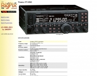 RigPix front and back side pictures of the Yaesu FT-450
 -
 Constructing a functional spectrum analyzer for the 0-100 MHz range presents a significant challenge for radio amateurs, often requiring specialized components and careful calibration. This project details a homebrew spectrum analyzer design utilizing common integrated circuits like the _SA605D_ FM receiver IC and _MAR-6_ MMIC amplifiers, aiming for a cost-effective solution. The design incorporates a low-pass filter, RF amplification, a voltage-controlled oscillator (VCO) for downconversion, and multiple IF stages at 150 MHz and 10.7 MHz, with a resolution bandwidth (RBW) of 15 kHz. Critical components such as the _SBL-1_ mixer and varicap diodes are specified, alongside instructions for winding inductors and tuning filters. The analyzer's performance is discussed in terms of input level limitations, specifically the 1dB-compression point and third-order intercept point, to ensure accurate measurements and prevent component damage. The _SA605D_'s logarithmic Received Signal Strength Indicator (RSSI) output serves as the detector, driving the Y-input of an oscilloscope, while a _TL084_ op-amp generates the sweep signal for the X-input. Potential enhancements include adding a step attenuator, improving front-end filtering, and implementing switchable IF filters for variable RBW, allowing for greater versatility in analyzing RF signals.
 -
 A portable 4 elements quad antenna for 144 MHz, 9 to 10 DBd forward gain, 30 DB front-to-back ratio, and 33 DB front-to-side ratio
 -
 This design was adapted from an article in the ARRL Handbook and built with simplicity and duplicity in mind. This antenna is a vast improvement over a standard dipole with a forward gain of around 8db with a front to back ratio of 10db.
 -
 Demonstrates the design and construction of a 9-element Yagi antenna for the **70 cm band** (432 MHz), based on the DK7ZB concept. The resource details EZNEC+ calculations for a single antenna, providing gain, sidelobe suppression, and front-to-back ratio figures. It also presents a comprehensive analysis of stacking two such antennas, including optimal stacking distance (1000 mm) and the resulting performance enhancements for the stacked array, such as an increased gain of 17.03 dBi. The article includes detailed drawings, wire file dimensions in millimeters, and azimuth/elevation plots for both single and stacked configurations. Practical construction steps are documented with original photographs, illustrating element mounting, the **28 Ohm matching system** using two quarter-wave 75 Ohm transmission lines, and the critical N-connector wiring. It also covers the iterative process of fine-tuning the driven element length to achieve a return loss of 20 dB, validating the EZNEC+ simulation results with actual measurements.
 -

-
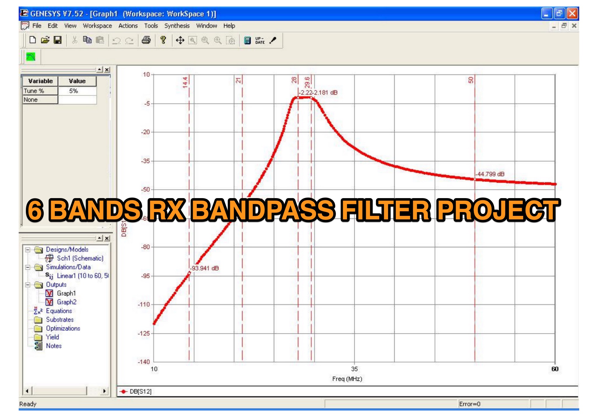 This is a 6 band receive only filter designed to protect your receiver front end and provide 45dB reject at the stop bands. This is a 6-band receive only filter designed to protect your receiver front end and provide 45dB reject at the stop bands. Stop band reject may be limited by the relay isolation. Worse case isolation is at 28 MHz or 35 dB or better. Relay K3/K8 protects the filter during transmit via the PTT line. A 25-50ms delay must be used between transmit and PTT. Do not rely on your radio to provide adequate delay with out using the PTT. You logging software must be set to allow a delay between PTT and time of 1st transmit. This filter will not work with VOX or QSK keying as you will damage the filter.
 -
 Balun Designs wind high quality baluns and ununs for Amateur Radio and commercial applications based on the researched and tested designs of Dr. Jerry Sevick, W2FMI.
 -
 Presents the design and performance of a 4-element wire Yagi antenna for the 40-meter band, building upon VE3VN's earlier 3-element switchable wire Yagi. The resource details the antenna's evolution, highlighting the transition from a 3-element to a 4-element configuration and the resulting improvements in gain and front-to-back ratio. It provides specific insights into the antenna's construction and expected operational characteristics. VE3VN shares insights from field results, noting the antenna's performance on 40 meters. The discussion includes the antenna's pattern and matching characteristics, crucial for any DXer or contester looking to optimize their signal on this popular HF band. The author's experience with the previous 3-element design informs the enhancements made to this 4-element iteration. The article includes a visual representation of the antenna's current view, offering a practical perspective on its physical layout. It serves as a valuable reference for hams considering a directional wire antenna for 7 MHz operations, demonstrating a practical approach to achieving enhanced directivity and gain.
 -
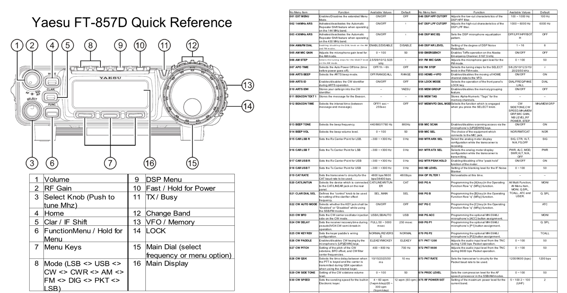 A PDF File to download and print, with a table of all menu options with values, default settings, description and a quick reference guide of the front panel menus
 -
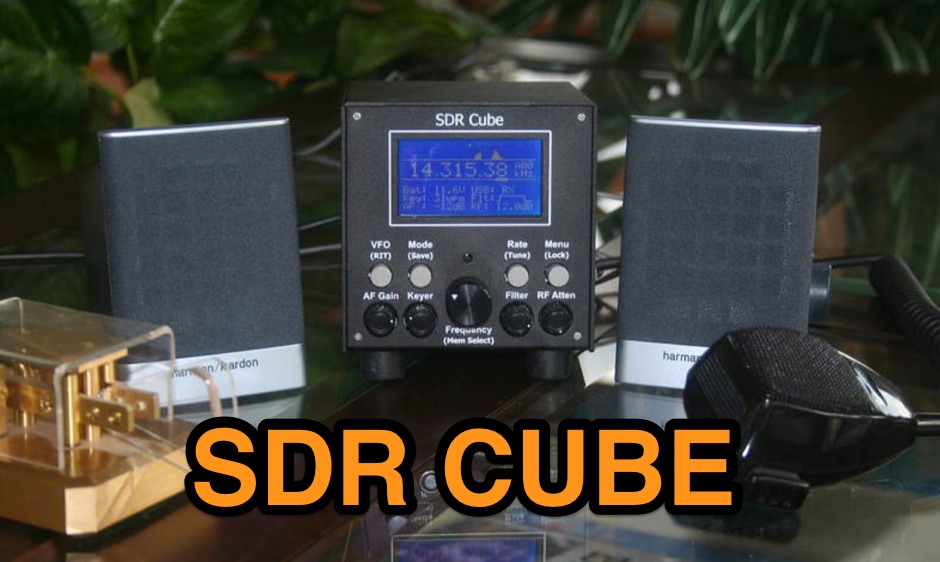 A self-contained and portable SDR Transceiver using a Softrock front end and embedded Digital Signal Processing ... No PC required!
 -
 Design for a 5 element 2 Metre beam with a forward gain of 8dBD and a front to back ratio of over 24dB.
 -
 This document details the design and construction of a Vinecom 6N4 dual-band Yagi antenna for the 50MHz (6-meter) and 70MHz (4-meter) amateur radio bands. The antenna features 9 total elements (4 elements for 50MHz, 5 elements for 70MHz) on a 4.236-meter aluminum boom. Computer simulations using MMANA software predict 7.21 dBd gain on both bands with front-to-back ratios of 16.01dB (6m) and 15.37dB (4m). The design uses 12.7mm diameter elements mounted on a 32mm square boom, weighing 5.7kg total. Practical measurements with an MFJ-269 analyzer confirmed good SWR performance across both bands after element length adjustments.
 -
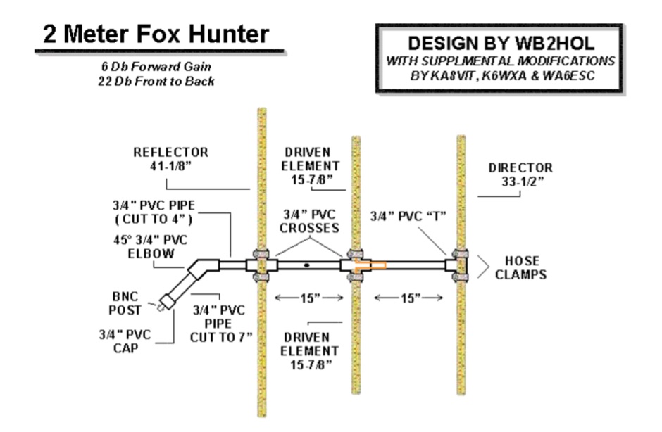 A home made yagi antenna featuring 6db forward gain and 22 Db front back
 -
 Examines PSKGNR, a software front-end specifically engineered to augment the functionality of existing PSK31 applications such as PSK31SBW and PSK31EVM. The resource details how PSKGNR integrates capabilities like typeahead for faster text entry, macro support for automating common phrases or commands, and other operational enhancements that streamline the PSK31 digital mode experience. It outlines the program's role in improving user interaction and efficiency during PSK31 QSOs by providing a more robust interface over the base software. The content highlights the practical benefits for digital mode operators seeking to optimize their workflow and reduce repetitive tasks. It positions PSKGNR as a utility for refining the user interface and adding advanced features to established PSK31 software platforms.
 -
 Demonstrates the construction and implementation of a **two-element phased vertical array** for 40 meters, utilizing _Christman phasing_ techniques. The author, W4NFR, details the process from building individual 1/4-wave aluminum verticals to integrating them into a phased system. The resource covers antenna spacing of 32 feet, elevated radial design, and the critical steps for tuning each vertical to achieve a 1.1:1 SWR before combining them. It also provides insights into calculating precise coax lengths for feedlines and the phasing delay line, emphasizing the use of an MFJ-269 Antenna Analyzer for verification. The finished system exhibits good front-to-back nulls, with an overall SWR ranging from 1.6:1 to 2.2:1, which is managed by an antenna tuner. The project includes detailed photos of the relay box, showing 12 VDC relays capable of handling 5KV, and the control box in the shack for switching between three different antenna pattern configurations. Static bleed-off chokes are incorporated for protection, and the construction emphasizes robust weatherproofing for outdoor elements.
 -
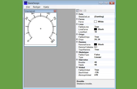 A danish only scale diagrams designer, usefull to draw front panels and dial scale knobs, windows freeware.
 -
-
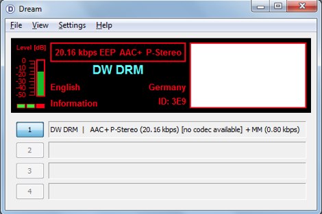 Open-Source Software Implementation of a DRM (Digital Radio Mondiale) Receiver. Dream runs on virtually any pc and requires a receiver front-end to work as a real radio.
 -
 Showcasing a specialized product line, Advanced Receiver Research presents a comprehensive catalog of **low noise preamplifiers** and microwave **Gunnplexers**. The offerings span a broad spectrum of radio frequencies, from VLF, LF, MF, and HF bands up through VHF, UHF, and microwave, catering to diverse applications including amateur radio, commercial installations, and military systems. Their product range includes mast-mount preamplifiers, inline attenuators, power dividers, and various coaxial components. My own experience with similar low-noise front ends for weak-signal work on 2 meters and 70 centimeters underscores the critical role such components play in maximizing receiver sensitivity, especially when chasing distant DX or engaging in EME. The detailed product descriptions and technical specifications provided on the site allow operators to select the optimal preamplifier for their specific band and noise figure requirements, essential for improving signal-to-noise ratio. The site also lists specialized products for unique applications like Nuclear Magnetic Resonance (NMR) and Studio Transmitter Links (STL), demonstrating a depth of engineering capability beyond typical amateur radio fare. This breadth of offerings, coupled with clear ordering and warranty information, positions Advanced Receiver Research as a key supplier for high-performance RF components.
 -
 The Yaesu FT-1000MP Mark-V, introduced at Dayton 2000 Hamvention, features a higher RF power of **200 W PEP** and a Class-A amplification SSB mode at 75 W. Key enhancements include an _Interlocked Digital/Analog Bandwidth Tracking system (IDBT)_, a Variable Front-End Filter (VRF) preselector, and improved ergonomics, notably a multi-function shuttle jog dial. This model, a successor to the 1996 FT-1000 and FT-1000MP, was designed to compete with high-end transceivers, despite its retail price of $4200 initially. The transceiver's physical dimensions are 406 x 135 x 348 mm (16 x 5.3 x 13.7 inches) with a weight of 14 kg (31 lbs), making it substantial. Its rear panel offers over 20 connections, including power, external DSP speaker, BAND DATA I/O, ALC, and multiple interface jacks for DVS-2, Packet, and RTTY. The unit also provides two keyer inputs, a DB9M serial interface for CAT, and two PL female antenna connectors, plus additional receive antenna jacks. Despite its advanced internal architecture, including two independent receivers with their own IF filters and AGC loops, the display technology, utilizing fluorescent discharge rather than LCD, contributes to an older aesthetic. The control panel is extensive, featuring 92 knobs and buttons, alongside numerous LED indicators for various modes and functions.
 -
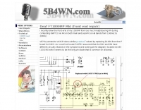 How to repair a FT1000MP front end, damaged from too much neighbouring RF during contesting
 -
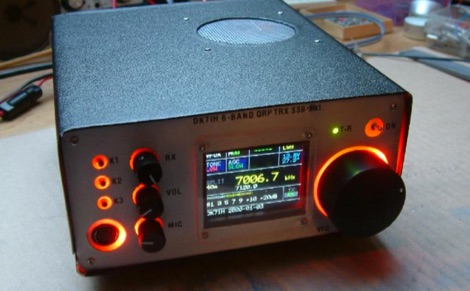 An SSB radio for the HF bands will be presented. Featuring 12 to 20 Watts of output power (depending on DC supply), full DDS frequency generation, covering 6 major frequency bands (1.8, 3.5, 7, 14, 21 and 28 MHz) within the short wave amateur radio spectrum. The rig also features colored LCD and front panel backlight.
 -
 The NB6Zep Antenna, an electrically shortened 80-meter end-fed wire, addresses space constraints for low-band operation by integrating two loading coils into a 37-foot wire. This design, modeled with _EZNEC_, explores configurations like the quarter-wave sloper and inverted-L, with the latter providing a more vertical radiation pattern and practical backyard deployment. The resource details specific coil construction, recommending 21 uH coils made from _BW coil stock #3026_ or similar, and outlines wire segment lengths for optimal tuning. Performance analysis indicates a radiating efficiency of approximately 27% with good ground conductivity, resulting in a signal typically 3-4 dB down compared to a full-size quarter-wave vertical. The antenna exhibits a narrow bandwidth, around 50 kHz, due to its high Q, necessitating a tuner for broader band operation. Feedpoint impedance is low, with ground resistance playing a critical role in achieving a usable SWR. The article emphasizes the importance of an effective ground rod at the feedpoint for proper operation and tuning, suggesting an antenna analyzer for precise adjustments. It confirms the antenna's suitability for DX, citing successful contacts from Oregon to the East Coast and Hawaii on a 160-meter variant, making it a viable option for urban operators seeking low-angle radiation on 80 meters.
 -
 Six elements yagi antenna for 6 meters band. This antenna design is based on the QuickYagi 4 software by WA7RAI, uses a 6.5 m boom, feature 12.0 dBi gain and 35dB front/back