Search results
Query: hf choke
Links: 28 | Categories: 0
-
 2-Element parasitic Yagis for the Shortwave-Bands 10-12-15-17-20-30m. The antennas are feeded with the DK7ZB-match. A quarter-wave choke of coax is grounded at the socket.
 -
 Presents a practical design for a **crossed-dipole turnstile antenna** specifically engineered for 2-meter Amateur Radio Direction Finding (ARDF) events. The author, WB6RDV, details a robust, omnidirectional, horizontally-polarized antenna, addressing the international ARDF rules requiring such characteristics at a height of two to three meters above ground. This contrasts with the vertical polarization often used in Southern California, highlighting the design's adherence to specific event requirements. The electrical design employs a classic crossed-dipole with a 75-ohm phasing section, resulting in a slight impedance mismatch and an SWR of approximately 1.3:1 with a 50-ohm feedline. Construction utilizes readily available and inexpensive PVC plumbing components and 1/8-inch bronze welding rod for elements. The guide provides step-by-step instructions for mechanical assembly, including drilling element holes at precise 90-degree spacing and preparing the RG-179 matching section. WB6RDV shares insights from his own build experience, discussing the use of plated brass versus aluminum spacers for element attachment and the effectiveness of crimping as an alternative to soldering. The document also covers final assembly, including the integration of ferrite beads as a choke balun and options for weatherproofing and alternative mounting configurations, emphasizing the adaptability of the design for other VHF bands through scaling.
 -
 Demonstrates the construction and performance of an updated ZS6BKW multiband dipole, a variant of the _G5RV_ antenna, specifically designed for HF operation. The article details a real-world installation using 13.5m copper wire elements and 12.2m of 450 Ohm ladder line, configured as a sloping inverted-V with the apex at 10m and ends at 4m above ground. It covers the critical aspect of impedance matching, incorporating an 8-turn choke balun at the feedline transition to RG-58U coax to mitigate RF common mode current. Measurements confirm favorable SWR readings below **1.3:1** on 7.1 MHz, 14.11 MHz, 18.06 MHz, and 24.8 MHz, indicating effective resonance across 40m, 20m, 17m, and 12m bands. The installation also shows usable SWR dips on 3.55 MHz (5:1), 29.02 MHz (2:1), and 50.84 MHz (3:1), extending its utility to 80m, 10m, and 6m with an antenna tuning unit. Initial on-air results report clear reception of stations over **5000km** away, validating its DX potential.
 -
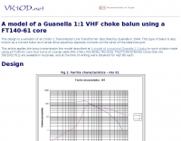 A model of a Guanella 1:1 VHF choke balun using a FT140-61 core
 -
 RF Choke to prevent hf currents on the feedline. This Magnetic Longwire Balun (MLB) makes it possible to efficiently use a coaxial lead-in cable with all forms of longwires, T-forms or other types of wire antennas, without the need for an antenna tuner.
 -
 RF Choke to prevent hf currents on the feedline or...1:1 Choke Balun, sometimes called the "UGLY BALUN"
 -
 Constructing a Lindenblad antenna for 137MHz NOAA satellite reception involves specific design considerations for optimal performance. The resource details the use of 4mm galvanised steel fencing wire, 300-ohm television ribbon cable, and wood/plastic components for the antenna structure. Key dimensions for a 137.58MHz-resonant antenna are provided, derived from the ARRL Satellite Handbook, specifying s, l, w, and d as 42, 926, 893, and 654mm respectively. The antenna is designed for Right Hand Circularly Polarised (RHCP) signals, requiring the four folded dipole elements to be tilted clockwise by 30 degrees. A significant aspect covered is impedance matching between the antenna's 75-ohm impedance and a typical 50-ohm receiver input. A twelfth-wave matching transformer, constructed from 117mm sections of 50-ohm RG-58 and 75-ohm RG-59 coax with a 0.66 velocity factor, is described. The article also addresses coaxial cable and connector selection, recommending 75-ohm Type-N connectors for RG-6 cable in professional setups and F56/F59 connectors for general use, while strongly advising against PL-259/SO-259 connectors for VHF. Strategies for mitigating Radio Frequency Interference (RFI) are discussed, including antenna placement to shield from local TV transmitters and the use of commercial or DIY band-pass filters, such as cavity resonators or helical notch filters, along with ferrite chokes on coaxial cables. Antenna orientation is explored, noting the Lindenblad's 'cone of silence' directly overhead and its maximized sensitivity towards the horizon. An experimental vertical tilt of 90 degrees is presented as a method to improve overhead reception and reduce interference from strong horizontal signals, particularly relevant in high RFI environments like the Siding Spring Observatory site.
 -
 The QRP choke balun described utilizes a high permeability ferrite rod and RG-174 coax, aiming to present high impedance to common-mode currents across the HF spectrum. The construction involves winding as many turns of RG-174 as possible around the ferrite rod, then encapsulating the assembly with hot glue. This design prioritizes maximizing inductance to suppress unwanted shield currents, particularly in unbalanced antenna configurations. While the balun's effectiveness is subjectively reported as good, a potential design consideration involves the dielectric properties of the hot glue. This material could increase turn-to-turn capacitance, potentially reducing the balun's performance at higher HF frequencies, though this specific aspect has not been formally tested by the author, _AA5TB_. The project serves as an illustrative example of a practical, junk-box construction rather than a rigorously engineered solution. Photographs detail the evolution of the balun, from the initial winding process to its integration within a _B&W dipole center insulator_ and final camouflaged assembly.
 -
 Demonstrates practical solutions for reducing **Radio Frequency Interference (RFI)** in amateur radio operating environments, specifically addressing issues with PC monitors, receivers, and transceivers. The resource compiles advice from experienced operators regarding the selection and application of ferrite cores, including split cores and toroidal cores. It details specific material types like **43, 73, 75, and 77 ferrite**, outlining their effective frequency ranges for RFI suppression, such as 43 material for 30-400 MHz and 77 material for 2-30 MHz. The content provides part numbers for various ferrite products from manufacturers like Fair-Rite Products Corp, distributed by Amidon, and discusses their impedance characteristics across different HF bands. It compares the performance of various ferrite materials at frequencies like 4 MHz, noting that 75 material offers 27 ohms, 73 material 17 ohms, and 43 material just under 10 ohms. Additionally, it touches upon the use of bypass capacitors in conjunction with ferrites to create low-pass filters, emphasizing the importance of identifying common-mode versus differential-mode RFI paths for effective mitigation.
 -
 BIRD RF power measuring, new and used, HENRY RF power amplifiers (used HF amps), TOHTSU coaxial relays, SAMLEX power supplies, RFI chokes reduce interference, Parts parts, tubes, Used amplifiers, radios, antennas and accessories, Los Angeles, CA.
 -
 A homemade VHF/UHF vertical antenna made essentially with RG58 coax cable, with a 9 turns choke balun to prevent the shield acting as a RF Radiator.
 -
 The G5RV multiband HF antenna, designed by Louis Varney (G5RV) in 1946, is a popular compromise antenna offering good overall performance on most HF bands when paired with an external antenna tuner. The basic full-size G5RV measures 102 feet across the top for 80 through 10 meter operation and is fed at the center via a 34-foot low-loss feed-stub. This interaction between the radiating section and the feed-stub facilitates matching across 80-10 meters with a standard tuner, often eliminating the need for ladder line directly to the shack. The antenna's design center frequency is 14.150 MHz, configured as a 3/2-wave dipole on 20 meters, with its 102-foot length derived from long-wire antenna formulas. Construction details emphasize the matching section, which can be open wire, ladder line (window-type), or TV twin lead. Each type has a specific velocity factor (VF) affecting its physical length for an electrical half-wave on 14 MHz; for instance, open wire requires 33.7 feet (VF 0.97), ladder line 31.3 feet (VF 0.90), and TV twin lead 28.5 feet (VF 0.82). The article provides formulas for calculating these lengths and discusses the antenna's behavior on individual bands, from 3.5 MHz where it acts as a shortened dipole, to 28 MHz where it functions as two three-half-wave long-wire antennas fed in-phase. Practical construction notes include recommendations for vertical descent of the matching section, sealing the coax junction, providing strain relief, and winding a coaxial choke coil to mitigate common mode current. The resource also presents dimensions for double-size (204 ft) and half-size (51 ft) G5RV versions, along with their corresponding matching section lengths for various line types, making it a versatile reference for hams considering this classic wire antenna.
 -
 The Resonant Feedline Dipole (RFD) HF antenna design utilizes a single piece of coaxial cable and a stranded wire section, forming a 1/4-wavelength radiator. This configuration, based on a 1997 ARRL Handbook design (page 20.17), functions by RF traveling on the inside of the coax shield and returning on the outside, creating the second half of the dipole. A choke wound into the feedline prevents RF current from flowing back down the feedline. Construction details include using RG-58a/u coax for a 75m version, with a 1/4-wavelength section of stranded wire soldered to the center conductor. The document provides choke dimensions for RG-213, RG-8, and RG-58 coax across 3.5 MHz to 28 MHz, specifying cable length and number of turns. Dipole dimensions are also tabulated for frequencies from 3.6 MHz to 28.4 MHz, listing overall length and individual leg lengths. Field tests included deployment near Bryson City at 5 feet off the ground and as a sloper during WCARS Field Day in Asheville, yielding successful local and regional contacts.
 -
 Optimizing the ZS6BKW antenna for full HF band coverage often requires specific modifications beyond its standard configuration. This resource details several enhancements, beginning with a simple series capacitor to improve 80m SWR, a technique W5DXP found effective for permanent installation due to its minimal impact on higher bands. Further improvements include a 10-inch parallel open stub for 10m resonance, shifting the frequency to 28.4 MHz with an SWR of approximately 1.8:1, a practical solution for Technician class operators. The document then explores a switchable matching section, adding or subtracting one foot of ladder line at the 1:1 choke-balun, which significantly impacts higher frequency bands and eliminates the need for a tuner on 17m. W5DXP's _AIM-4170D_ antenna analyzer measurements confirm these effects. More advanced modifications involve a parallel capacitor for further 80m SWR reduction, requiring remote switching for multi-band operation, and relay-switched parallel capacitors at specific points on the 450-ohm matching section to achieve low SWR on 60m, 30m, and 15m. These detailed steps, including _Smith chart_ analyses for the challenging bands, aim to transform the ZS6BKW into a truly all-HF-band antenna, reflecting W5DXP's practical experience in antenna tuning.
 -
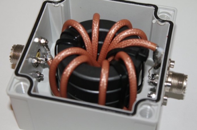
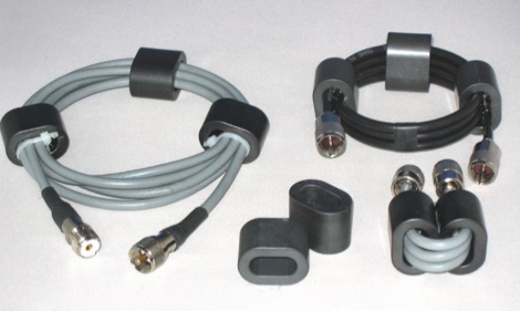 In this article the author describes some new designs of ferrite loaded chokes for suppressing unwanted common mode currents at HF applied to feed lines like choke baluns, but also in the shack, applied to various coaxial, mains and data cables
 -
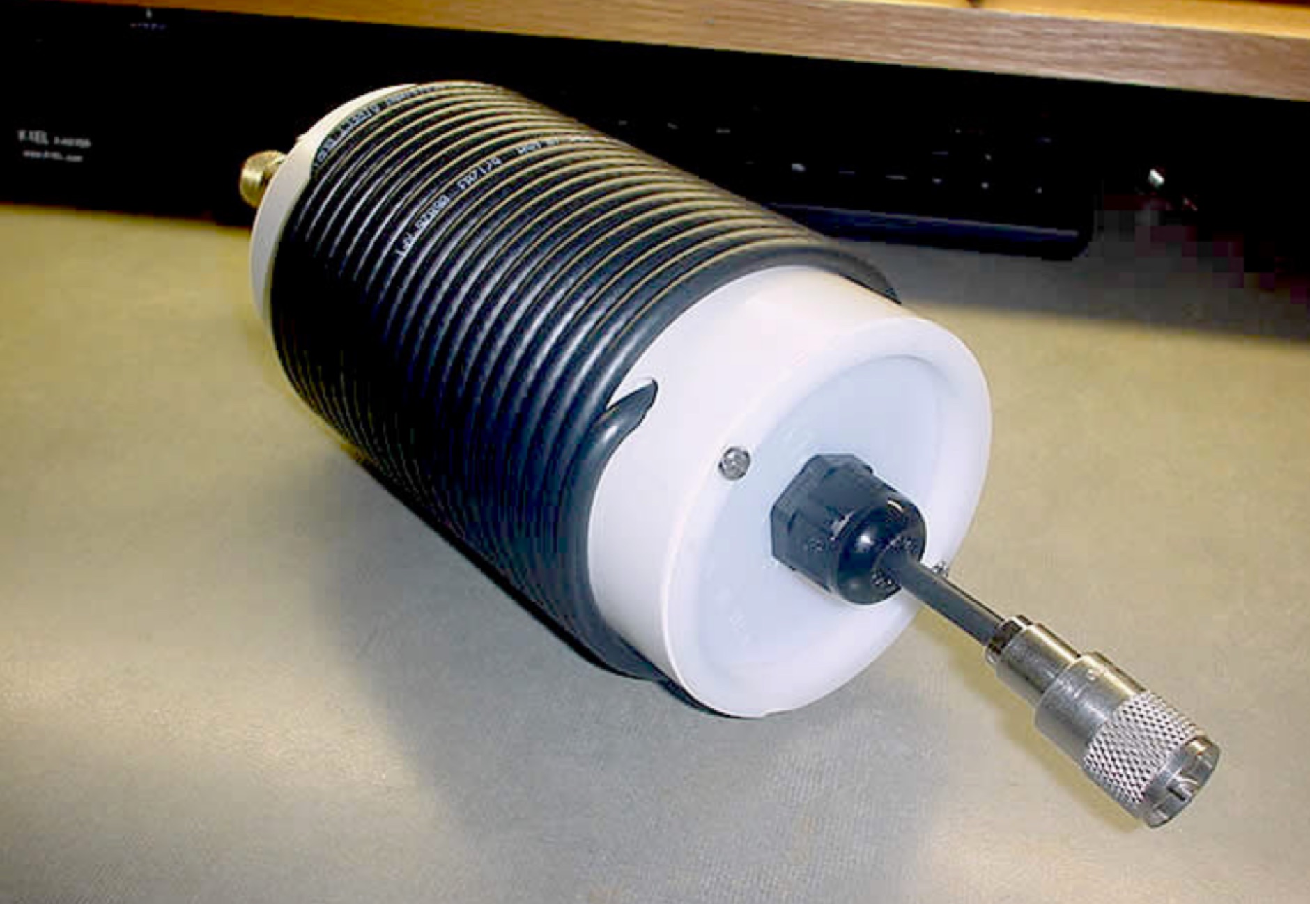 The main function of the Ugly Balun is to help eliminate rf currents from flowing on the outside of coaxial cable using the principle of choke action.
 -
 How to homemade a multi-band HF dipole using 100 meter of speaker wire, 2 strandsm including a homebrew 1:1 choke balun
 -
 May 2015 Radcom Article on common-mode chokes that can be used for control cables, phone lines, but mostly on typical HF antenna systems. This article explain what common mode chokes does, why you meay need one, properties common mode chokes should have, how to build and measure performances.
 -
 The _Sci.Electronics FAQ: Repair: RFI/EMI Info_ document, authored by Daniel 9V1ZV, provides a detailed analysis of computer-generated RFI/EMI, focusing on its impact on radio reception. It identifies common RFI sources such as CPU clock rates (e.g., 4.77 MHz to 80 MHz), video card oscillators (e.g., 14.316 MHz), and even keyboard microprocessors, all of which generate square-wave harmonics across HF and L-VHF regions. The resource outlines a systematic procedure for pinpointing RFI origins, including disconnecting peripherals and using a portable AM/SW receiver with a ferrite rod antenna to localize strong interference sources. The document categorizes RFI mitigation into shielding, filtering, and design problems, offering practical solutions for each. It recommends applying conductive sprays like _EMI-LAC_ or _EMV-LACK_ to plastic casings of radios, monitors, and CPUs to create effective Faraday cages, emphasizing proper grounding and avoiding short circuits. For filtering, the guide suggests using line filters, ferrite beads, and toroids on power and data lines, and small value capacitors (e.g., 0.01 uF for serial/parallel, 100 pF for video) to shunt RFI to ground. It also discusses the use of bandpass, high-pass, low-pass, and notch filters on the receiver front-end or antenna feed to combat specific in-band noise.
 -
 Constructing a dual-band antenna for 40 and 20 meters often involves compromises in size or complexity. This resource presents a compact _open sleeve dipole_ design that addresses these challenges by using 450-ohm ladder line and folded elements to achieve a total length of approximately **17.17 meters**, significantly shorter than a full-size 40-meter dipole. The design leverages electromagnetic coupling, where a primary radiator handles the 40-meter band, and a second conductor resonates on 20 meters without direct electrical connection. This configuration eliminates the need for traditional traps, loading coils, or switching components, simplifying construction and reducing potential loss points. The antenna is fed with RG-58C/U coaxial cable, and a common-mode choke is recommended at the feed point to suppress sheath currents, ensuring a cleaner radiation pattern and minimizing RF in the shack. The design is well-suited for portable operations, field deployments, temporary installations, and restricted urban environments where space is a premium, offering solid performance on both HF bands.
 -
 Discovering a solution for limited space, the inverted L HF antenna emerges as a stellar performer. Half the size of a dipole, it ensures optimal installation in restricted areas, maintaining superb transmission (TX) and reception (RX) characteristics. Spectrum Communications' multi-band version, featuring traps, proves even more space-friendly without compromising performance. A fiberglass pole offers sturdy support, while proper grounding, an RF choke, and occasional tuning contribute to a high-performing and reliable antenna system.
 -
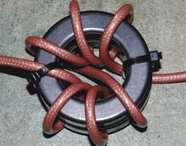
 Choking balun for lower HF and MF bands. (1.8MHz - 10MHz). Requiring a choking balun to isolate the potential RF pick up on the coax cable as it runs past equipment such as computer within the radio room at lower HF and MF frequencies a simple method of winding RG58 coax onto a Powdered Iron Toroid Core was constructed.
 -
 Home brewing a high performance, high power common mode choke for HF bands
 -
 The mini Radio Solutions miniVNA PRO is the only affordable vector network analyser (VNA) I know of that offers remote wireless operation. This is very interesting because it allows to measure the input impedance of HF antennas installed at height without having to deal with coax cable lengths, baluns nor common mode suppression chokes. However, to render the miniVNA PRO truly field proof, it requires a number of significant modifications.
 -
 This article describes the construction of a simple dual-band VHF/UHF end-fed vertical dipole antenna designed for local repeater access using an Icom IC-705 radio. Built from a single piece of RG58U coaxial cable, the antenna consists of a 460mm exposed inner conductor, 450mm of intact coax, and a 9-turn choke balun wound on a 27mm former. Mounted on a 10m Spiderpole, the antenna achieves excellent SWR readings (<1.2:1 on 2m, <1.5:1 on 70cm) and provides effective coverage of local repeaters with unexpected reach into distant locations.
 -
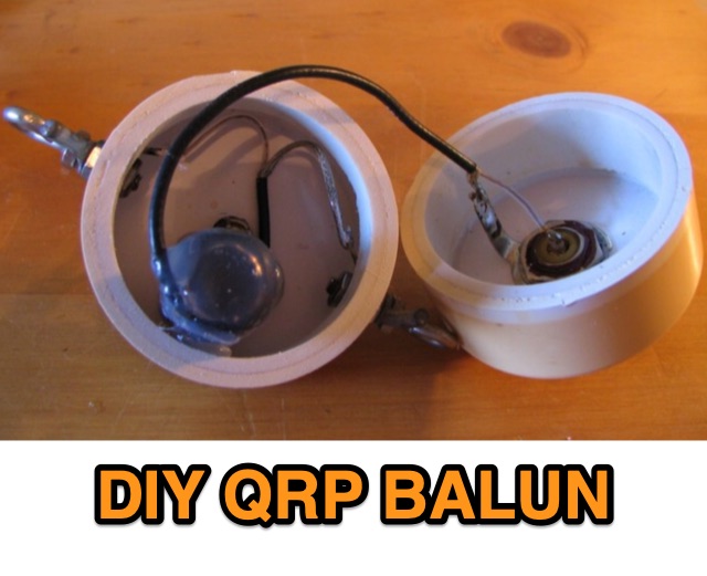 DIY project of a QRP Balun. Using a high permeability ferrite rod and an old B&W dipole center insulator, he constructs a choke type balun for QRP use. The balun aims to create as much inductance as possible at HF, offering a high impedance to common mode currents
 -
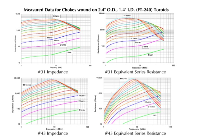 FT-240 toroids measurements. The data was measured using well-calibrated HP instrumentation. All plots have been adjusted to a frequency range of 1-100 MHz on the horizontal axis and a resistance/impedance range of 10-1,000 ohms on the vertical axis. This adjustment facilitates comparison among different materials and aids in determining their suitability for use on the HF ham bands.
 -
 Demonstrates practical **rules of thumb** for selecting and utilizing ferrites and coils in amateur radio projects, particularly for RF applications up to 30 MHz. It addresses common challenges like determining appropriate ferrite grades and estimating L/C values without precise specifications. The resource details the author's experience with readily available grey ferrites, noting their suitability for HF work, and provides guidance on constructing **baluns** and RF chokes, balancing inductance for lower frequencies against inter-wire capacitance for higher frequencies. It also outlines a method for estimating power handling based on ferrite weight, suggesting a 1-gram ferrite can manage over 2 Watts, and offers a technique for evaluating unknown ferrites by winding 10 turns and measuring resonance with a 1 nF capacitor. This approach emphasizes a hands-on, iterative method for balun winding and adjustment, allowing operators to quickly approximate component values. The article compares the characteristics of ferrite-cored coils with air-cored coils, highlighting the reduced pickup and radiation of ferrite designs. It refines the air-coil estimation method for frequencies between 2.5 MHz and 10 MHz and provides a scaling factor for frequencies outside this range, aiming to get operators into the correct general area for their designs. The author's standardized ferrite choice (RND Components 165-00182) is presented as a practical example for reproducible projects.