Search results
Query: lc design
Links: 177 | Categories: 3
-
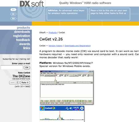 CwGet v2.55 is a software application for amateur radio operators designed to decode Morse code (CW) signals into text using a standard computer sound card, eliminating the need for specialized hardware. The program features a customizable interface with a spectrum display for visualizing signal frequencies and peaks, an oscillogram for monitoring signal presence and setting detection thresholds, and a received symbols window for displaying decoded text. Key functionalities include Automatic Frequency Control (AFC) to lock onto signals, adjustable FIR and IIR filters for noise reduction, and a burst filter to mitigate short noise impulses. It also supports automatic CW speed detection, multiple character sets, and the ability to record and replay received audio. Integration with logging software like AALog is facilitated through double-click word transfer, and transceiver frequency control is possible via the Omni-Rig interface, allowing for automatic tuning of the radio's VFO or RIT. The multi-channel decoder feature can simultaneously decode up to five strong signals within a 1600 Hz bandwidth, displayed in a separate Multi-RX Window with an adjustable squelch. CwGet also offers the capability to decode signals from pre-recorded WAVE files and can function as a narrow-band sound DSP filter for aural decoding. This is a commercial version and it has been tested on latest MS Winows versions.
 -
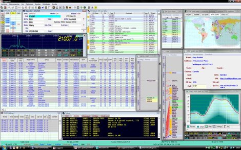 Logger32 is a well-established amateur radio logging program designed primarily for DXers who require a flexible and data-driven logging environment. The software maintains a comprehensive logbook database capable of handling large volumes of QSOs while offering detailed tracking of DXCC entities, awards, and band/mode statistics. One of the core strengths of Logger32 is its DX cluster integration. The program connects to telnet DX clusters and displays spots in real time, with filtering options by band, mode, country, or callsign. The cluster window can automatically highlight needed DXCC entities, band-fills, or new modes based on the operator’s log. Logger32 also provides rig control through CAT interfaces, supporting a wide range of transceivers via serial or USB connections. When properly configured, frequency and mode are automatically captured in the log entry window. The software supports digital mode integration through external applications and can exchange information using standard interfaces. Another important feature is its award tracking system, including DXCC, WAS, IOTA and other common amateur radio awards. The program calculates worked, confirmed, and needed entities with detailed reports. Logger32 supports ADIF import and export, allowing interoperability with other logging systems. It also includes QSL management, with tracking for bureau, direct, and electronic confirmations such as LoTW or eQSL when configured. Overall, Logger32 remains a technically capable logging solution focused on DX tracking, cluster awareness, and detailed statistical analysis of operating activity.
 -
 Author evaluated a custom-built passive AM loop antenna, achieving notable DX reception including KLBJ Austin (230 miles) and WWL New Orleans (700 miles). The antenna operates solely on resonant inductive coupling, enhancing weak signal reception without external amplification. This project illustrates how fundamental RF design—calculating inductance, capacitance, and Q factor—can significantly boost performance of consumer-grade radios. Detailed construction techniques, theoretical background, and optimization strategies for effective loop antenna design are presented for amateur and experimental use.
 -
 Details the construction of a **multiband vertical** antenna, specifically designed for stealth operation in a rented property, covering 80m, 60m, 40m, and 30m. The author, N3OX, leverages a 12m Spiderbeam telescoping fiberglass pole as the primary support, noting its sturdiness compared to typical fishing rods while remaining light enough for quick deployment and takedown. The radiating element is a 14 gauge Flex-Weave wire, attached to the pole's top with a rubber grommet, and fed by 27 bare 18 gauge radials spread across a 40-foot square backyard. N3OX describes the impedance matching solution, opting for custom-built L-networks over a remote tuner to enable fast bandswitching. Using an MFJ-259B and EZNEC modeling, base impedances were measured and component values calculated with G4FGQ's L_TUNER and SOLNOID_3 programs. The 80m coil is wound on a 3.5-inch PVC form, while the 30m, 40m, and 60m coils are air-wound, self-supporting #10 wire. Variable capacitors are incorporated for 40m and 30m shunt elements, with the 60m impedance matched by a series inductor. The project includes a **servo-controlled** homebrew band switch, utilizing a two-pole 12-position ceramic wafer switch for remote operation, addressing the limited 80m bandwidth. The entire matching network is housed in a weather-resistant shelter constructed from lumber and aluminum flashing. N3OX reports good DX results at 100W, estimating the total cost between $150 and $250, depending on existing parts.
 -
 Complete guide to build Jpole antennas with online dimensions calculator.
 -
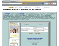 This basic calculator is designed to give the aproximate length (height) of a particular vertical antenna, for the frequency and wavelength chosen.
 -
 Details the construction of a J-vertical antenna specifically for the 10-meter band, offering a practical alternative to a _Slim Jim_ design for 28 MHz. The resource outlines the use of aluminum tubing for the half-wave vertical section and coaxial cable for the quarter-wave matching section, providing specific calculations for element lengths based on frequency and coaxial cable velocity factor. It contrasts the performance of the J-vertical with center-fed dipoles and end-fed verticals, noting superior results in previous comparisons. The article further presents a more recent iteration of the J-vertical, constructed using a fiberglass pole and insulated wire, with updated dimensions for 28.8 MHz. It includes practical advice on weatherproofing connections and securing the antenna for durability against adverse conditions, referencing the survival of an original _J Vertical_ during 110 MPH winds in 1987. The SWR performance is reported as 1.1:1 at 28.6 MHz, maintaining below 1.5:1 across 28.3 to 29 MHz.
 -
 calculates the dimensions and spacings of the elements needed to build a log periodic antenna, given tao, sigma and the lower and upper cutoff frequencies.
 -
 The Cubical Quad antenna is a popular choice among amateur radio operators due to its robust design and excellent performance characteristics. This resource provides essential scaling formulas that help determine the lengths of the antenna elements and the necessary gamma match values for various frequencies. The design is adaptable, allowing operators to optimize for gain or front-to-back ratio by adjusting the spacing between elements. The accompanying Excel files facilitate precise calculations, making it easier for both beginners and experienced hams to construct their own Cubical Quad antennas. In addition to the design formulas, the resource includes practical insights from the author, who has successfully built and utilized these antennas in various field events. The document outlines the tuning process for achieving minimum VSWR, ensuring optimal performance. With detailed illustrations and performance data, this guide serves as a comprehensive reference for anyone looking to delve into Cubical Quad antenna construction and optimization, enhancing their amateur radio experience.
 -
 HamCalc is a free collection of calculators for radio amateurs include Antenna ERP calculations, Attenuators, Audio Filter design, Coil Winding, Decibels, Great Circles map and calculator, HF Filters, HF Traps, Metric conversions OP Amps QRA Locator to Latitude/Longitude, Radio Horizon calculator, Resonance Satellite orbit calculator Timer calculations (555 timer)Zener Diode calculations Download zip By G4VWL
 -
 Design your own 5/8 wave vertical antenna. A simple jscript calculator at Antenna Elmer.
 -
-
 The project details a DIY SWR/Wattmeter designed around an _Arduino Uno_ shield, providing capabilities to measure RF power from 2 to **200 watts** and Standing Wave Ratio (SWR) for HF amateur radio bands. This construction features a compact design, integrating the measurement circuitry directly onto a custom PCB that interfaces with the Arduino Uno microcontroller. Key components include a directional coupler for sensing forward and reflected power, precision rectifiers, and analog-to-digital conversion for processing RF signals. The Arduino firmware handles calibration, calculations, and displays the results on an integrated LCD, offering real-time feedback on antenna system performance. The design prioritizes simplicity for homebrewers. Performance specifications indicate accurate readings within the **2-200W** power range, suitable for typical QRP to medium-power HF operations. The project provides schematics and a basic overview of the software logic.
 -
 J-pole Design Program V1.1 by WA2ISE Download a VHF twinlead Jpole antenna calculator MSDOS program
 -
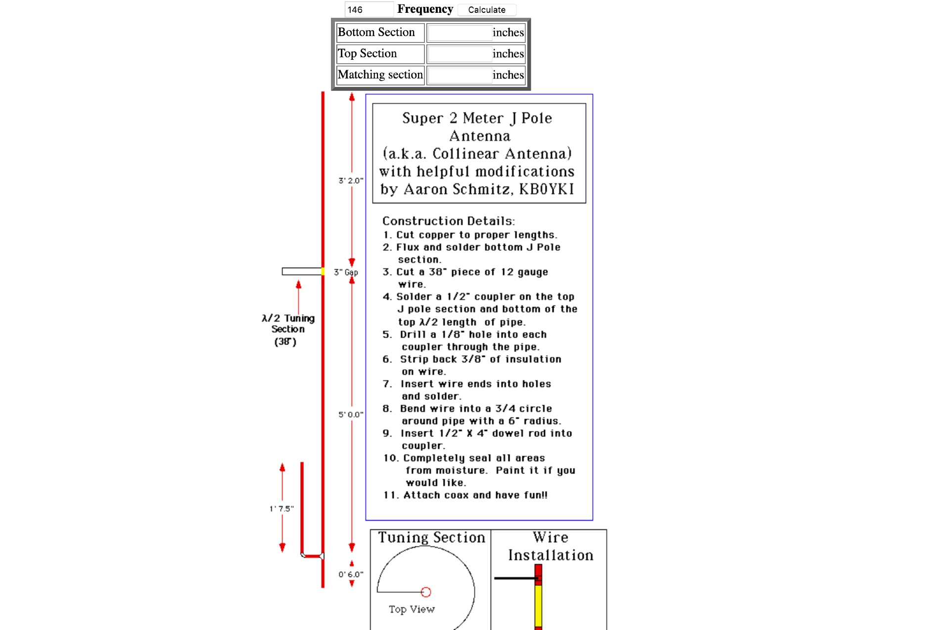 Javascript for calculating the lengths of tubing to be used for the construction of a Super J-Pole in a collinear design
 -
 An on-line javascript calculator and quite a few pictures to show how to make a helix antenna.
 -
 Amateur Contact Log (AC Log) by N3FJP is a commercial Windows-based general logging program designed for amateur radio operators, supporting Windows 7 through 11. It provides comprehensive tracking for various operating awards, including Worked All States (WAS), Worked All Counties, Worked All Countries (WAC), DXCC, VUCC, Grids, Zones, IOTAs, and Lighthouses. The software features a customizable user interface, allowing operators to display specific data fields and adjust font sizes. It includes built-in databases for counties and countries, facilitates queries by band, mode, or power level, and offers a bearing and distance calculator for DX contacts. AC Log also provides DX spotting via Telnet or packet TNC, supports keyboard CW, and can play wave files. The program offers full support for ADIF import and export, enabling seamless integration with external services like eQSL, QRZ, Club Log, and the ARRL's Logbook of the World (LoTW) for QSO uploads and confirmation downloads. It interfaces with popular transceivers from Elecraft, Icom, Kenwood, Ten Tec, and Yaesu, and connects with digital mode software such as WSJT-X, Fldigi, and JTAlert via API. AC Log includes a Net Manager form for group logging, prints basic QSL label strips, and integrates with QRZ and Ham Call lookup services. The software is fully networkable for multi-PC operation, supports Parks on the Air (POTA) logging, and displays worked entities and DX spots on a real-time world map. Full featured Trial version available for 45 days
 -
 Antenna Scatterers Analysis Program, is a Free general purpose antenna analysis software program for numerical electromagnetic antenna design, modeling and analysis. Source code and windows executables are available to download.
 -
 The Flower Pot Antenna project details a portable dual-band antenna primarily operating on 10 meters, with secondary resonance near the 30-meter band. Construction involves winding RG58 coaxial cable uniformly around a large plastic flower pot, approximately 70cm high with a 60cm top diameter. The design eliminates the need for radials, contributing to its compact and lightweight nature. Key construction steps include soldering the inner conductor to the shield at one end of the wound cable and connecting the wound cable's shield to the rig cable's inner conductor at the base. An LC network, comprising a variable capacitor (0-200pF) and an inductor (10 coils, 5cm diameter, 2mm wire), is inserted between the wound cable's inner conductor and the rig cable's shield. Tuning is performed with an antenna analyzer, adjusting cable length and the variable capacitor for optimal impedance on 10 meters. The antenna performs effectively when installed horizontally.
 -
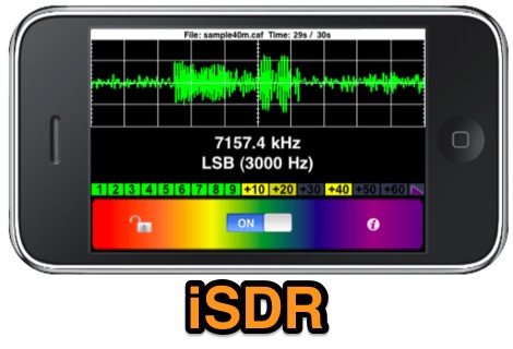 iSDR is a software defined radio application compatible with the Apple iPhone, iPod touch and iPad. iSDR is designed for experimenters, shortwave listeners, and amateur radio enthusiasts who would like a truly portable software-defined radio receiver.
 -
 The project details modifications to an ARK-40 QRP CW transceiver kit, specifically replacing its original thumbwheel frequency selectors with a **BASIC STAMP BS-II microcontroller** and an optical shaft encoder. The redesigned control circuitry outputs a BCD code to the ARK-40's synthesizer, enabling more convenient knob-type tuning. This modification significantly alters the user interface, moving from discrete frequency selection to continuous tuning. Operating frequency is presented on an LCD readout, offering two distinct display modes: a "bandspread dial" mode that simulates an analog dial scrolling across the display in 1 kHz increments, and a conventional digital readout with 100 Hz resolution. Pushing the main tuning knob toggles between these modes, providing both rapid band traversal and fine-tuning capabilities. The software for the BASIC Stamp is written in P-Basic, addressing the challenge of accurate analog dial simulation. Physical modifications include fabricating a custom PC Board for the STAMP, mounting it with an L-bracket to the optical encoder, and creating a new front panel. The front-mounted speaker was relocated to accommodate the new tuning knob and display, transforming the **ARK-40 transceiver** into a more user-friendly rig with its built-in CW keyer and 5 watts of power.
 -
-

-
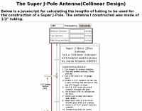 a Javascript for calculating the lengths of tubing to be used for the construction of a Super J-Pole.
 -
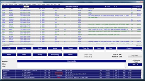
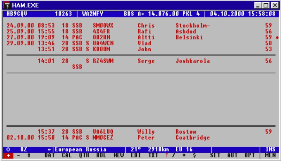 Facilitates efficient logging of amateur radio contacts, offering a robust solution for hams managing their station activities. The software integrates _CAT control_ capabilities, allowing direct interfacing with popular transceivers from manufacturers like Yaesu, Icom, and Kenwood. This feature streamlines the logging process by automatically capturing frequency, mode, and other QSO details directly from the radio, reducing manual entry errors and improving operational efficiency during contests or DXing. _HAM-LCT_ includes a comprehensive database, enabling users to store and retrieve contact information, QSL data, and other relevant details for each QSO. The program supports various operating modes and provides tools for searching and filtering log entries, which is beneficial for award tracking and station analysis. Its design focuses on providing a user-friendly interface for everyday logging tasks. While the original author, _HB9CQV_, has discontinued development of HAM-LCT in favor of a newer logging application, this version remains available as a functional freeware option for Windows users seeking a dedicated logbook with integrated rig control.
 -
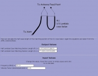 Online calculator for a 4 to 1 coax cable balun
 -
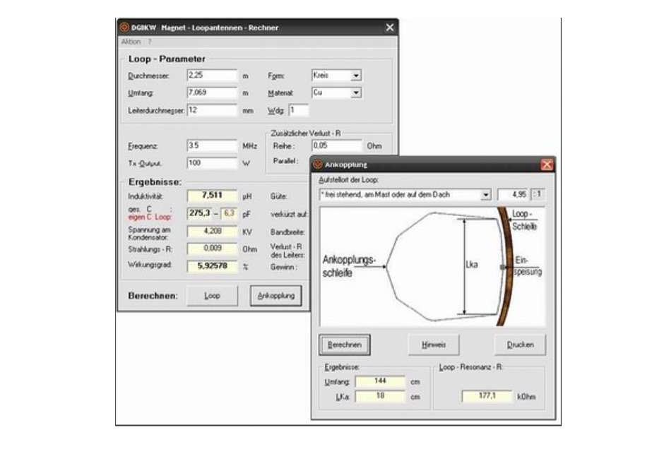 Magnetic loop antenna calculator and loop antenna design program for windows let you calculate dimensions for magnetic loops antennas, in german
 -
 Quagi antenna design, this little windows application let you calculate dimensions of elements and spacing of a quagi antenna. Freeware by VE3SQB
 -
 F6EZX presents a detailed account of constructing a compact, multi-band _Levy antenna_ for portable holiday operations, specifically addressing issues with local QRM from a previous _Deltaloop_ setup. The article outlines the design criteria, including multi-band operation on 40m, 30m, 17m, 15m, 12m, and 10m, a symmetrical configuration to reduce interference, and a low take-off angle for DX. Construction involves 2x 10.3m radiating elements and a 15.3m open-wire feeder (ladder line) with 7cm spacing, made from 1.5mm2 copper wire and foam pipe insulation spacers. Theoretical calculations, referencing F9HJ's "_Les antennes Levy_" book, guide the determination of element lengths and feeder impedance characteristics, aiming for a good match across bands with a commercial antenna tuner. Initial field tests with the _VCI Vectronics VC300DLP_ tuner showed a 1:1 SWR from 80m to 10m, with some difficulty on 17m. The antenna, mounted as a 45-degree slopper with the high point at 12m, successfully facilitated DX contacts to South America, particularly Chile and Argentina, suggesting a lower take-off angle compared to the previous Deltaloop which favored Brazil. The Levy antenna significantly reduced TVI/RFI, attributed to its improved symmetry and greater distance from the QRA. While signal reports on 15m and 20m were 1-2 S-points lower than the Deltaloop, its performance on 40m and 30m was comparable, fulfilling the design goals for a portable, low-cost, multi-band solution.
 -
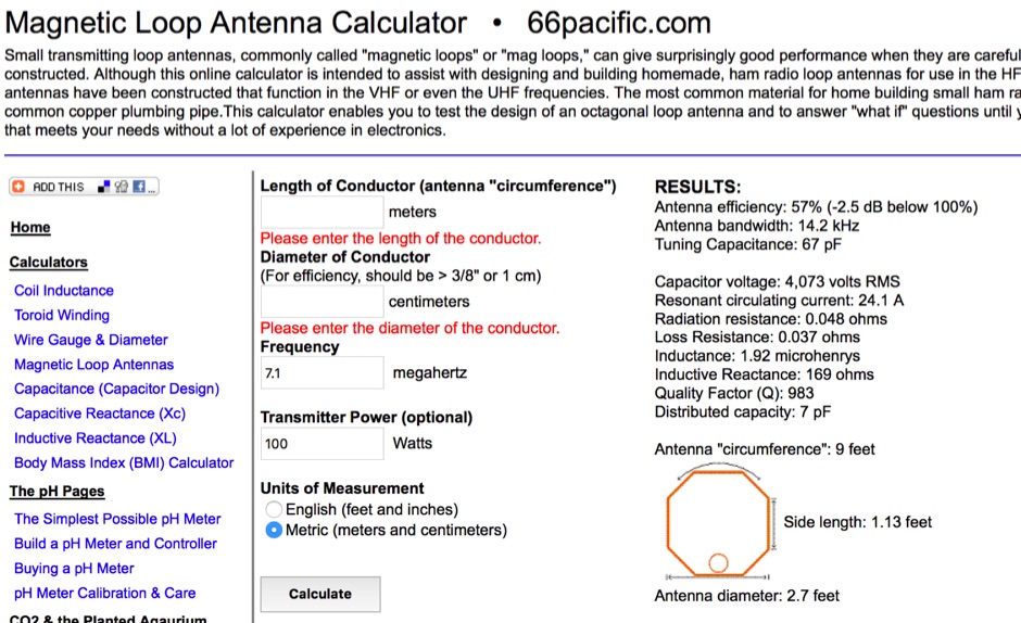 A free online calculator for making all of the calculations required to design and build small transmitting loop antennas, also known as magnetic loops by 66pacific.com
 -
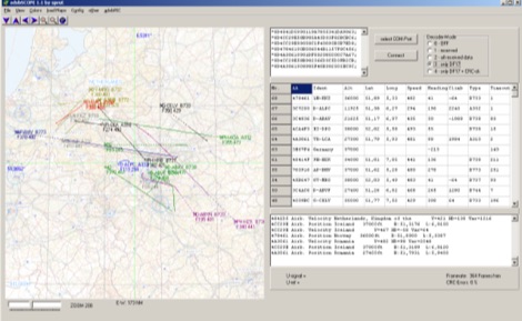 adsbScope is a freeware Windows application designed for processing _ADS-B_ (Automatic Dependent Surveillance-Broadcast) frames received from a compatible decoder. It identifies aircraft, calculates their real-time positions, and presents flight parameters in both alphanumeric tables and a graphical display. The software interfaces via a virtual COM port, receiving raw frames to provide detailed situational awareness, including a global coordinate grid, continental coastlines, over 4,000 **airport** locations, and major cities. Users can overlay OpenStreetMap tiles and view world state boundaries, with each tracked aircraft rendered with labels showing altitude, speed, heading, squawk code, and flight identifiers. When paired with the adsbPIC-decoder, adsbScope enables advanced hardware control, allowing users to toggle data filters for specific frames like DF17/18/19, adjust analog signal thresholds for reception fine-tuning, and manage system resets or bootloader activation directly from the PC. This functionality provides a customizable toolkit for hobbyist radar listeners, offering a robust alternative to commercial tools for processing aircraft data. The software displays up to **1090 MHz** transponder data and can track aircraft up to 250 nautical miles.
 -
-
 Log periodic antenna design excel sheet file download, in italian.
 -
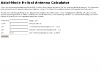 This is my simple implementation of the ARRL Antenna Book design equations for the axial-mode helical antenna.
 -
 Inverted V antennas is a dipole with the center raised on a mast and the endpoints near ground. Calculate dimensions online.
 -
 A 40-meter reversible _Moxon rectangle_ antenna project details its construction and performance, featuring 51-foot long sides and 7.7-foot turned-in sections. The design incorporates a 16.5-foot boom, with elements spaced 1.1 feet apart, constructed from #14 covered wire. It utilizes two double-pole relays for switching between NE and SW directions, achieving F/B ratios up to 40 dB on CW and 30 dB on SSB, with distinct reflector stub settings for each mode. This antenna replaced a full-size 2-element Yagi, demonstrating comparable forward gain while offering superior F/B ratios and directional flexibility. _EZNEC_ modeling indicates only 0.2 dB less forward gain than the Yagi. The system uses no baluns, relying on half-wave feedlines and switched stubs for impedance matching. The antenna is tree-supported at 45 feet, with its effective radiation height modeled at 80 feet due to local terrain, enhancing its performance over a nearby lake.
 -
 Mirko Pelcl's extensive radio collection features numerous historical transceivers and receivers, with a significant focus on military communications gear. The collection includes notable examples such as the Wireless Set No. 19, various Cold War-era military radios, and even a rare WWII spy radio utilizing a Loewe 3NF tube. Visitors can explore detailed sections dedicated to sets manufactured before 1945, including those used for military exchange, and a separate category for post-1945 radios, particularly those from the former Yugoslavia. The site also delves into specific modifications, like a digital head conversion for the RU-20, and showcases a frequency counter built with a microcontroller. This personal archive provides a unique glimpse into the evolution of radio technology, from early vacuum tube designs to more modern solid-state military transceivers like the PRC-515. The content reflects Mirko's dedication to preserving and documenting these pieces of radio history.
 -
 End-Fed Half-Wave Antennas (EFHWAs) are analyzed for their utility in portable QRP operations, emphasizing their simplicity, efficiency, and predictable radiation patterns compared to other portable antenna types. The discussion contrasts EFHWAs with vertical antennas, random length wires, and center-fed dipoles, highlighting the common pitfalls of each, such as ground system dependency for verticals and feedline issues for dipoles. The article details the electrical half-wavelength calculation using the formula L (Ft) = 468/F(MHz) and explains how EFHWAs can be resonant on harmonic frequencies, enabling multiband operation. Various deployment configurations are presented, including the inverted L, inverted Vee, sloping wire, and vertical setups, each with specific advantages for radiation angle and polarization. For instance, a vertical EFHWA offers a low angle of radiation suitable for DX contacts without requiring an extensive ground system. The resource also addresses the counterpoise requirements, suggesting a quarter-wavelength wire or connection to a metallic structure for decoupling. A schematic diagram for a simple parallel-tuned circuit tuner, based on the _Rainbow Bridge/Tuner_ design, is provided, detailing component values for 30 and 40 meters, including a 6 microhenry toroidal inductor and a 20-100 picofarad mica compression capacitor. The tuner's adjustment process for SWR matching is also outlined.
 -
 PA3FWM's software defined radio (SDR) page documents his extensive hardware and software development efforts between 2004 and 2009. Initial experiments utilized a direct conversion receiver with 90-degree phase difference, feeding a PC soundcard at 48 kHz sample rate, covering 24 kHz of spectrum around a 7080.5 kHz local oscillator. This setup, similar to AC50G's QEX 2002 article, allowed for basic I/Q signal processing to distinguish signals above and below the LO frequency. Limitations included fixed crystal frequencies, 16-bit dynamic range, and narrow bandwidth. Subsequent hardware iterations aimed for enhanced performance, incorporating external 24-bit ADCs with 192 kHz sample rates, connected via 10 Mbit/s Ethernet. A **MC145170-based PLL** and programmable octave divider provided a 58 kHz to 30 MHz tuning range. The **Tayloe mixer** was employed, with differential outputs feeding a PCM1804 ADC. An ATmega32 microcontroller handled serial data conversion to Ethernet frames, though without CRC calculation due to processing constraints. Later designs integrated AD7760 2.5 Msamples/second ADCs and a Xilinx Spartan-3 FPGA, enabling direct reception of 0-1 MHz spectrum and eventually 2.5 MHz bandwidth across the shortwave spectrum. Software was refactored to use an initial 8192 non-windowed FFT for efficient high-bandwidth processing. The project culminated in a two-way QSO on 21 MHz using the developed hardware and software, demonstrating transmit capabilities with a D/A converter. The system exhibited a 2.5 MHz wide spectrum display and a zoomed 19 kHz display, capturing signals like ionospheric chirp sounders and RTTY contest activity. Challenges included noise leakage from digital circuitry and cooling for high-power dissipation components.
 -
 This PDF document, authored by KT4QW in October 2004, details the construction and modeling of a dual-band, horizontally polarized hanging rectangular loop antenna for **10 and 17 meters**. The design, adapted from *The ARRL Handbook*, utilizes _NEC4WIN95_ software for scaling and optimization, targeting a 50 ohm feedpoint impedance. The resource includes a bill of materials, step-by-step construction instructions, and a discussion of the antenna's radiation characteristics. It presents NEC-generated elevation and azimuth patterns, comparing the loop's performance to a half-wave horizontal dipole at the same height and frequency. The 17-meter element is centered at 18.140 MHz for low SWR across the phone band, while the 10-meter element is centered at 28.500 MHz. Construction involves 14-gauge stranded copper wire and Schedule 40 PVC spreaders, with the total wire length calculated by the formula: Length in feet = 1005/MHz. The feedpoint impedance can be adjusted by modifying the rectangular aspect ratio. The document specifies hoisting the antenna to at least a half-wave above ground for testing. It notes that a balun was tested and found to have no measurable effect on SWR or radiation characteristics. A 2-meter scale model is presented to illustrate the physical design, and a "rotator" string is incorporated for directional adjustment up to 90 degrees.
 -
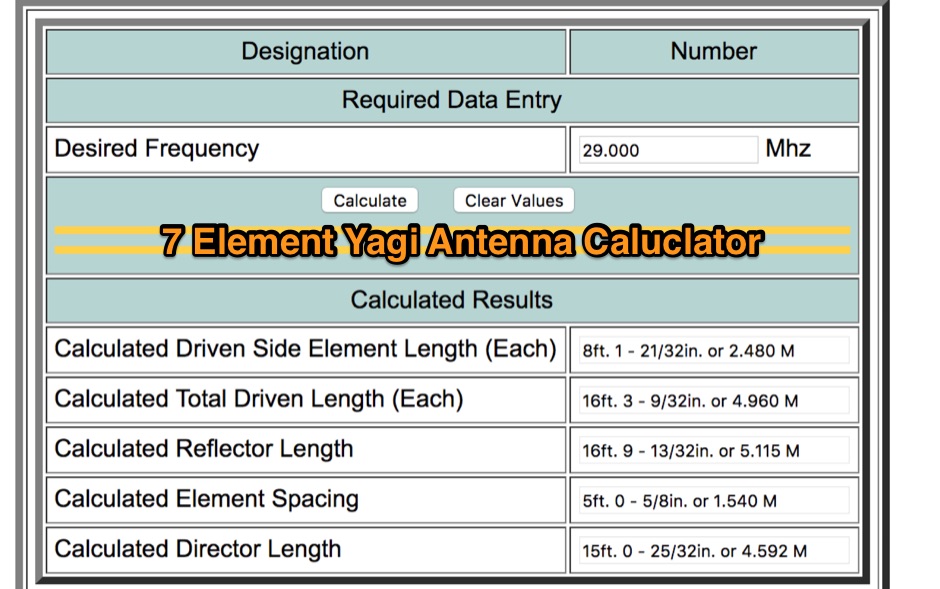 Online javascript antenna calculator designed to give the critical information of a particular beam antenna, in this case a seven element Yagi, for the frequency chosen.
 -
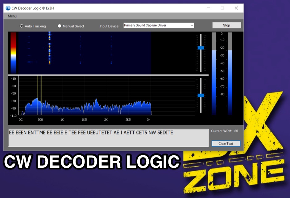 Demonstrates CW Decoder Logic, a freeware application for Windows Vista SP2, 7, 8, and 10, designed to decode Morse code signals. The software incorporates an optimized 80 Hz DSP filter, enabling reception of CW signals across a speed range of 5 to 60 WPM. Key features include automatic signal tracking within a 3 KHz range, real-time speed detection, and an auto squelch function, enhancing decoder sensitivity and accuracy. The application provides station selection directly on a waterfall display and includes a "Tips" feature for word annotations. It supports sending decoded text to external logging software via UDP protocol, with a logger source code example provided for developers. Configuration options allow users to set speed limitations and customize interface elements. Released initially on October 17, 2016, with subsequent updates, the program requires Microsoft .NET Framework 4.5 or higher. Changelogs detail improvements such as increased program stability, code optimizations for speed, and fixes for display issues across different Windows versions.
 -
 Online Moxon antenna calculator. Design your moxon antenna online giving wire diameter and resonant frequency
 -
 Manufacturer of Fibreglass Whip Antennas, Low and mediun Frequency, HF and VHF Antennas Specialized in the design and manufacturing of a full range of Beacon (MF), AM Broadcasting 540 - 1700 KHz, HF 1.7 to 30 MHz, VHF 30 to 156 MHz and UHF 200 to 500 MHz antennas.
 -
 Managing extensive amateur radio contact logs efficiently requires specialized software that integrates various operational aspects. Aether provides a macOS-native logging solution, designed from the ground up using Apple's Cocoa, to streamline QSO entry, organization, and retrieval for Mac users. It supports modern macOS technologies and offers an intuitive interface, aligning with the user experience expected on Apple platforms. The application includes features such as automatic dupe checking, which quickly identifies previous contacts with a station, and awards tracking, indicating if a new contact is needed for specific operating awards. Aether also integrates rig control via RS-232, automatically populating frequency, mode, and power data from supported Elecraft, Icom, Kenwood, Yaesu, and some TEN-TEC transceivers. This automation reduces manual entry errors and speeds up the logging process. Furthermore, Aether offers comprehensive QSL management, including synchronization with eQSL.cc and Logbook of The World, and the ability to print QSO detail and address labels for paper QSLs. It also incorporates automatic callbook lookup from sources like QRZ.com and HamQTH.com, and calculates distance and beam heading, with Google Maps integration for visualizing contact locations. Full ADIF and Cabrillo import/export capabilities ensure compatibility with other logging software and contest submission platforms.
 -
 Constructing a compact, two-band magnetic loop antenna for HF operation, especially from constrained locations like a balcony, presents unique challenges. OK1FOU's design, inspired by DJ3RW's 50 MHz loop, addresses these by employing an unusual side-fed configuration and placing the symmetric, two-section variable tuning capacitor at the bottom of the loop, directly connected to the coax shield. The article provides specific material recommendations, including two 1-meter wooden pales and about 3 meters of thick loudspeaker cable, noting the high current (60A at 100W) in the loop. Construction steps detail forming two turns with a 5 cm gap, using a GDO to pre-tune the open loop to a frequency slightly above the desired highest band, and then integrating the tuning and coupling capacitors. For 10/14 MHz, an open loop resonance of 16-17 MHz is suggested. Practical experience with the 10 MHz band from a third-floor balcony in Prague (JO70GC) shows a 1:1 SWR across most of the band without an external ATU. While DX traffic was modest due to the urban environment, QSO examples with RA6WF, LA6GIA, G0NXA, and LZ1QK on 10 MHz are provided, demonstrating its operational capability.
 -
 A circular waveguide calculator for designing cantennas include source code and windows executable by lincomatic
 -
 G4URH calculations to design your own antennas, ground plane, half wave antennas, Quad Antennas and 5/8 verticals
 -
 ERP Calculator is an Amateur Radio software utility designed to perform a side-by-side comparison of two Ham Radio antenna systems. ERP Calculator comes pre-programmed with data files including published data for several popular brands and types of coax cable as well as several popular antenna system brands and models. ERP Calculator displays values of ERP, Antenna Power Gain, Antenna Feed point Power, Antenna System Gain in dB, Antenna Gain in dBd, SWR Attenuation in dB, SWR Power Attenuation, Coax Loss in dB, and Coax Power Loss
 -
 This resource details the computer-optimized design of the _ZS6BKW_ multiband dipole, an evolution of the classic _G5RV_ antenna. It begins by referencing the original 1958 RSGB Bulletin article by Louis Varney G5RV, explaining the operational principles of the G5RV's flat-top and open-wire feedline on 20m and 40m, noting its impedance transformation characteristics for valve amplifiers of that era. The article then transitions to the rationale for optimizing the design for contemporary solid-state transceivers requiring a 50 Ohm match. The core of the project involves using computer modeling to determine optimal lengths for the flat-top and matching section, aiming for a VSWR of less than 2:1 on multiple HF bands. It discusses the process of calculating feedpoint impedance based on antenna length and frequency, referencing professional literature from Professor R.W.P. King at Harvard University. The analysis also considers the characteristic impedance (Z(O)) of the open-wire line, identifying a broad peak of adequate values between 275 and 400 Ohms. Specific design parameters for the improved ZS6BKW are presented, including a shorter flat-top and a longer matching section compared to the original G5RV, with a velocity factor of 0.85 for the 300 Ohm tape. The article confirms acceptable matches on 7, 14, 18, 24, and 28 MHz bands when erected horizontally at 13m, and also discusses performance in an inverted-V configuration, noting frequency shifts. The author, Brian Austin ZS6BKW, emphasizes the antenna's suitability for modern 50 Ohm coaxial cable without a balun.