Search results
Query: loss antenna
Links: 84 | Categories: 0
-
 Demonstrates the construction of **magnetic loop antennas**, detailing both multi-turn and single-turn designs. It covers a 30-inch diameter multi-turn loop for 80 meters, based on a February 1996 QST article, and an octagon single-turn loop made from 15mm copper tube with a 4.8-meter circumference, operating from 7 MHz to 14 MHz. The document also presents a smaller 800mm diameter loop for 14 MHz to 28 MHz, emphasizing the importance of high-voltage tuning capacitors. Covers the design and construction of custom **butterfly capacitors** and piston capacitors, including a split stator capacitor with 140 pF capacitance and a 6000 Volt rating, and a butterfly capacitor with 5-65 pF and 7200 Volt rating. It explains why butterfly capacitors are preferred over split stator types for high power applications due to lower losses and direct series connection of rotors, reducing resistive losses from wiper contacts. Material recommendations include clear PVC for plates and brass or stainless steel for non-magnetic hardware. Addresses practical considerations such as feeding the loop with a shielded 1/5 Faraday loop made from RG213 or RG8 coax, achieving VSWR 1.1 across bands, and optimizing its placement 180° from the capacitor. It also discusses mechanical joint resistance, dissimilar metal oxidation prevention using Vaseline, and a simple method for determining radiation angle with a TL-light tube. The guide includes diagrams for rotor, stator, and end plate construction.
 -
 This PDF article from April 2001 QST details the construction of the "NJQRP Squirt," a reduced-size 80-meter inverted-V dipole antenna. The resource provides a general construction sketch, a photograph of the assembled antenna, and specific dimensions for PC-board insulators. The antenna consists of two wire legs, each approximately **34 feet long**, separated by 90 degrees, fed at the center. It is designed for operation on 80 meters (3.5-4.0 MHz) as a quarter-wavelength antenna, requiring a low-loss feedline and an external antenna tuner due to its non-resonant feedpoint impedance. Construction utilizes readily available materials, including 1/16-inch glass-epoxy PC board for end and center insulators, and #20 or #22 insulated hookup wire for the elements. The feedline specified is 300-ohm TV flat ribbon line, with a note on potential trimming for tuner compatibility. N2CX reports the antenna's center should be elevated to at least **20 feet**, with ends no lower than seven feet above ground, resulting in a ground footprint of approximately 50 feet wide. The design prioritizes NVIS propagation for local 80-meter contacts. DXZone Focus: PDF Article | 80m Inverted-V Dipole | Construction Notes | 34 ft element length
 -
 Determining the actual need for an antenna tuner often hinges on the specific antenna and feed line configuration in use. While many hams believe a tuner is always essential, its primary role is to present a 50-ohm impedance to the transceiver, not to "tune" the antenna itself. For instance, a resonant dipole fed with _coaxial cable_ at its design frequency typically requires no tuner, as the feed line impedance closely matches the radio's output. However, operating a non-resonant antenna, or using a resonant antenna on multiple bands, frequently necessitates a tuner to manage high Standing Wave Ratio (SWR) on the feed line. The article clarifies that a tuner placed at the transceiver only matches the radio to the feed line, not the antenna to the feed line. For maximum efficiency with a non-resonant antenna, an _automatic antenna tuner_ (ATU) or a remote tuner placed at the antenna feed point is often more effective, minimizing losses in the feed line. The discussion also touches on the practical implications of SWR, noting that modern transceivers often fold back power at high SWR, making a tuner a practical necessity to achieve full output power, even if the antenna itself is not perfectly matched.
 -
 Details the construction and optimization of antenna systems for amateur radio satellite operations, focusing on practical, homebrew solutions for VHF/UHF bands. It covers building _groundplane antennas_ from salvaged materials, recycling old beam antennas into new configurations like a 2-meter crossed yagi, and constructing a 10-meter horizontal delta loop. The resource also explains antenna matching techniques, including folded dipole driven elements and quarter-wave transformers, along with the importance of accurate SWR measurements and minimizing coax loss. Demonstrates how to achieve a **1:1 SWR** by carefully trimming elements and adjusting radial angles on groundplane antennas. It provides insights into selecting appropriate coax and connectors, highlighting the benefits of Belden 9913 for low loss and the proper installation of _N-connectors_. The article also addresses RFI mitigation from computer birdies and presents a design for a silent triac antenna control circuit, offering practical solutions for common satellite station challenges.
 -
 Presents the KE4UYP linear-loaded vertical antenna design, which introduces very little loss on 80 or 160 meters, achieving an overall radiation efficiency of 80% to 85%. This design addresses common pitfalls of traditional base-fed verticals by placing the majority of the current at the top of the antenna, eliminating the heavy reliance on extensive ground radial systems. The author's initial 10-meter model, only three feet tall, yielded 5/9 signal reports to Anchorage, AK, and Europe, confirming its effectiveness. The antenna incorporates both vertically and horizontally polarized radiators, with a 1/4 wavelength horizontal counterpoise located at the feed-point, near the top, to create an almost totally omnidirectional pattern with high wave angle horizontally polarized radiation. This dual polarization ensures even illumination across all take-off angles, making it effective for both local contacts and **DXing**. The vertical element is linear loaded, adding capacitance reactance and making it longer than the horizontal element to achieve resonance and raise the feed-point impedance to 50 ohms. Fine-tuning the antenna requires careful adjustment, as tower reactance can vary. The article suggests starting with 80 feet for 80m and 170 feet for 160m for the vertical wire, then trimming for resonance. Bandwidth specifications include 300 kHz under 2:1 **SWR** on 80m and 100 kHz on 160m when suspended between trees, or 150 kHz on 80m when side-mounted on a tower.
 -
 The 80-meter loop antenna, measuring 86 meters (282 feet) of wire, effectively operates across 8 HF bands from 80 through 10 meters, despite its length being a compromise for specific bands. This design prioritizes a "low enough" SWR across multiple bands, aiming for lower SWR values on higher frequencies due to increased feedline losses. A 200-ohm feedpoint impedance provides a workable SWR on every band, with feedpoint impedances ranging from 100 ohms for lower bands to 300 ohms for higher bands. Radiation patterns for the 80-meter loop, mounted at 15 meters high, show a maximum gain of 7.6 dBi at a 90-degree takeoff angle on 80 meters, and up to 12.9 dBi at a 10-degree takeoff angle on 12 meters. This configuration supports regional contacts on 80 meters and provides good DX performance on higher bands. Practical construction notes emphasize using robust supports like trees, ensuring wire slack with _egg insulators_ for wind resilience, and employing an oversized 2 kW 4:1 _balun_ to safely handle higher SWR conditions, even with 100W transceivers. Feedline losses are minimized using _LMR-400_ coax or ladder line, with power transfer efficiency between 80% and 95%. Antenna simulations were performed using _xnec2c_, and the provided NEC file is compatible with other NEC2 derivatives. The antenna is tunable on 6 of 8 bands with an internal ATU and all 8 bands with an external autotuner like the LDG AT-200 Pro.
 -
 Selecting an appropriate antenna system for shortwave broadcasting involves evaluating various types based on performance, cost, and operational parameters. This resource details the critical specifications for broadcast antennas, including average and peak power ratings, directivity, takeoff angle (TOA), horizontal beamwidth, and gain, emphasizing that a 100-kW transmitter requires an antenna rated for 150 kW average and 400 kW peak. It clarifies that low TOA signals travel thousands of kilometers, while high TOA is for local coverage, and nearly all modern shortwave broadcast antennas are horizontally polarized. The article explores specific antenna types, such as Log-Periodic Antennas (LPAs), which offer wide frequency ranges (e.g., 2-30 MHz) and directional patterns with 11 dBi gain, costing from $20K to over $100K for multi-curtain versions. Dipole arrays, also known as curtain antennas, are prevalent in international broadcasting, featuring steerable beams (±15° and ±30°) and mode-switching capabilities to alter TOA, with high/low pairs costing over $1 million. Fan dipoles are noted for omnidirectional patterns, smaller size, and lower cost for low-power applications, while rhombics, though simple, require resistive termination and incur several dB of I2R losses. Balun considerations are crucial, as most communications baluns are not rated for the higher average and peak powers of AM broadcast transmitters. Modern shortwave antennas utilize durable materials like Alumoweld wire rope for radiators and support elements, avoiding copper, fiberglass, or materials prone to stretching or deterioration. Feeder systems for high-power stations often require tapered-line baluns to convert 50-ohm unbalanced power to 300-ohm balanced for connection to the antenna.
 -
 Interesting article on mobile antennas by Cebik. . The article offers advice for setting up and operating mobile antennas for ham radio use. It emphasizes the lossy nature of mobile-in-motion antennas but encourages users to rise to the challenge. Steps include safeguarding car electronics, choosing proper cabling, and carefully selecting and mounting antennas. It highlights potential issues like roof mounting, trunk lip grounding, and side-mounting for trucks. For stationary operation, options like dipoles or beams are explored, with safety tips for masts and guying systems. Lastly, it stresses safety, suggesting stopping the vehicle to operate whenever possible
 -
 The ZS6BKW multiband HF antenna, a design by ZS6BKW (G0GSF), functions effectively on multiple HF bands without requiring an Antenna Tuning Unit (ATU) for 40, 20, 17, 12, 10, and 6 meters. This antenna, approximately **27.51 meters** (90 feet) long with a 12.2-meter (40-foot) open-wire feeder, is a direct descendant of the _G5RV_ but offers superior multi-band resonance. It can be deployed as a horizontal dipole or an inverted-vee, with the latter requiring only a single support and maintaining an apex angle of at least 90 degrees to prevent signal cancellation. Performance data, recorded with an MFJ Antenna Analyser, indicates SWR values of 1:1 on 7.00 MHz (40m) and 14.06 MHz (20m), with SWR below 1.3:1 on 17m, 10m, and 6m. While primarily designed for these bands, the antenna can be adapted for 80m, 30m, and 15m with an ATU, preferably at the balanced feeder's base. The use of 450-ohm twin-lead for the feeder is recommended over 300-ohm for improved strength and reduced losses, especially in adverse weather conditions. This design, originally published in _RadCom_ in 1993 and featured in Pat Hawker’s "Antenna Topics," provides a compact and efficient solution for HF operation, particularly for those with limited space or resources.
 -
 A **90-foot tall** top-loaded vertical antenna for the 160-meter band is detailed, constructed from aluminum irrigation tubing. The design incorporates four sets of four guy wires for structural stability, essential for an antenna of this physical size. This _monoband_ vertical is optimized for low-band operation, providing a robust solution for DXing and contesting on 1.8 MHz. The document includes specific construction methods for assembling the aluminum irrigation tubing sections and securing the guy wires. While a full NEC model is not explicitly provided, the physical dimensions and construction materials are sufficient for replication by experienced builders. The antenna's height and top-loading configuration are critical for achieving efficient radiation on 160 meters, particularly in minimizing ground losses.
 -
 The document details the optimization and construction of the _Maria Maluca_ antenna, a compact 6-band (20m-6m) directional beam. It presents a comparative analysis of shortwave antenna principles, highlighting the efficiency gains achieved by using an open feeder line and tuner as a resonant unit, contrasting this with the losses associated with traps or capacitive loads in multiband antennas. The resource specifically revisits an older South American 2-element design for 10, 15, and 20 meters, applying modern NEC-based software to develop a six-band version. Performance data is meticulously tabulated, showing impedance, free space gain, gain at 12m height, elevation angle, and front-to-back (F/B) ratio for each band from 20m through 6m. For instance, on 15m, the antenna achieves 5.1 dBd free space gain and 13.72 dB F/B ratio. The construction section provides practical guidance on element assembly using aluminum pipes and hose clamps, detailing the use of a heavy-duty glass fiber reinforced polyamide rod for electrical separation and bending strength. It also specifies the use of 450-ohm _Wireman_ line CQ 552 for the transmission line. The document includes diagrams for rod fixing, an air-wound balun, and a vertical elevation diagram for the 15m band, illustrating its DX qualification. It also discusses the antenna's suitability for portable and expedition operations, noting its compact transport dimensions (max 1.50m length, 12 lb weight) and quick assembly time (under 15 minutes). The author, Dipl.Ing. Helmut Oeller, DC6NY, is identified as a source for material kits.
 -
 Testing and comparison of traps and trap antennas
 -
 ERP Calculator is an Amateur Radio software utility designed to perform a side-by-side comparison of two Ham Radio antenna systems. ERP Calculator comes pre-programmed with data files including published data for several popular brands and types of coax cable as well as several popular antenna system brands and models. ERP Calculator displays values of ERP, Antenna Power Gain, Antenna Feed point Power, Antenna System Gain in dB, Antenna Gain in dBd, SWR Attenuation in dB, SWR Power Attenuation, Coax Loss in dB, and Coax Power Loss
 -
 This article explores a theoretical model for the losses of an 80m / 40m trapped inverted V dipole antenna system using a bootstrap coax trap, but does not examine the pattern of the antenna.
 -
 DAVIS RF Co. has been in the business of supplying the staples of wire antennas for over 30 years. DAVIS RF Co. supply all coax cables, all connectors, ladder line, rotar control cable, insulators, and we have the largest selection of wire for wire antennas. DAVIS RF Co. is the designer and trade mark holder, and primary source for Bury-Flex Tm low loss coax cable. PolyStealth Tm high strength PE insulated antenna wire, and Flex-Weave Tm wire
 -
 A self supporting vertical antenna for 80 meters by W9OY include pictures and construction details
 -
 Coax is a very important part of a satellite station. It is almost as important as the antennas you choose. This article discusses choosing coaxial cables for satellite communication, emphasizing factors like line loss. It compares types such as RG-8, RG-58, Belden 9913/9913F, LMR-400, and hardline, highlighting their impact on signal preservation.
 -
 Calculate Cable Loss from SWR and reverse. Text file with only two simply formulas
 -
 Demonstrates the design and construction of a 9-element Yagi antenna for the **70 cm band** (432 MHz), based on the DK7ZB concept. The resource details EZNEC+ calculations for a single antenna, providing gain, sidelobe suppression, and front-to-back ratio figures. It also presents a comprehensive analysis of stacking two such antennas, including optimal stacking distance (1000 mm) and the resulting performance enhancements for the stacked array, such as an increased gain of 17.03 dBi. The article includes detailed drawings, wire file dimensions in millimeters, and azimuth/elevation plots for both single and stacked configurations. Practical construction steps are documented with original photographs, illustrating element mounting, the **28 Ohm matching system** using two quarter-wave 75 Ohm transmission lines, and the critical N-connector wiring. It also covers the iterative process of fine-tuning the driven element length to achieve a return loss of 20 dB, validating the EZNEC+ simulation results with actual measurements.
 -
 One specific challenge in the KazShack, operating Single Operator Two Radios (SO2R), involved sharing a K9AY receive antenna between two transceivers without direct RF connection or manual feedline swapping. The solution, detailed in this project, adapts the **W3LPL RX bandpass filter** design to split 160m and 80m signals, feeding them to separate radio inputs while maintaining isolation. This approach also addresses the issue of strong broadcast band interference from a nearby 50KW WPTF transmitter on 680kc. The construction utilizes T-50-3 toroids and NP0 ceramic capacitors, built in a "dead bug" style on copper clad board. Each band's filter coils are identical and resonated to the desired frequency using an MFJ-259 antenna analyzer. A single DPDT relay, controlled by a remote toggle switch mounted on an aluminum panel, facilitates quick band switching between radios, simplifying low-band operations. While some signal loss is noted, the expected lower noise levels from the receive antenna are anticipated to compensate, potentially reducing the need for constant volume adjustments during toggling between transmit and receive antennas.
 -
 Various publications through the years have shown how the SWR measured on a shorted (or open) feed line can be used to calculate feed line attenuation
 -
 This calculator is designed to give the efficiency loss of a given antenna, based on the input of VSWR (voltage standing wave ratio) and other subsequent factors
 -
 About beverage antennas, Enhanced F/B Beverages, Bandwidth of Directivity, arrays. This article describes two phasing systems for Beverage antennas that improve directivity and cancel rearward signals. These systems use lossy elements and require minimal components to achieve broadband performance.
 -
 Connecting centre fed antennas, dipoles, yagis, rhombics, loops to coaxial cable, unless care is taken, it is not difficult to end up with feeder radiation resulting in power loss and the radiation characteristics changes
 -
 GW4ALG's _136 kHz Pages_ document the evolution of vertical antennas for the 2200m band, starting with a prototype mounted on a house wall. This initial design, despite achieving the first **395 km** GM-GW QSO, suffered from significant insulation breakdown, high RF losses due to proximity to the house, and difficult tuning adjustments. The author details the challenges of maintaining resonance and matching with a variometer in the loft, noting that adding three earth spikes offered no measurable improvement over a simple water tap connection. The subsequent experimental 12m vertical, relocated away from the house, significantly reduced dielectric losses and proved far more effective. This antenna enabled GW4ALG to set a world DX record on 136 kHz with a **1916 km** QSO to OH1TN, and an intra-UK record of **703 km** to GM3YXM/P. The resource further explores the use of helium-filled balloons to extend the vertical radiator, achieving heights up to 27m, typically 20m, for enhanced low-band performance. Practical advice on balloon types, inflation, and critical insulation between the wire and balloon is provided, emphasizing safety and avoiding arcing.
 -
 The Vee Beam antenna project presents a versatile solution for hams, enabling operation across all eight High Frequency bands (80m to 10m) with significant gain on 20m to 10m. This easy-to-construct antenna utilizes two long wires at an angle, enhancing directional performance and minimizing ground losses. With a low visual profile, it is discreet and effective for various applications. The design allows for optimal leg lengths and included angles, ensuring robust performance while maintaining simplicity in construction and operation. The V Beam antenna is an aerial that you can use on all eight High Frequency amateur bands (80, 40, 30, 20, 17, 15, 12 and 10m) with an antenna tuner, and which gives significant gain on the five bands from 20 to 10 meters band.
 -
 SimSmith is a highly interactive, real time Smith chart graphing program. Circuits are constructed using drag-n-drop. Load files can be imported from the EZNEC and CocoaNEC antenna simulation software and from the AIM4170 and miniVNApro antenna analyzers. Circuits and load files can be of any size. Key Features: SimSmith is one of the few Smith chart packages which models transmission line losses. SimSmith also allows the description of circuit elements using algebraic equations. SimSmith has only one screen and allows the screen to be resized to increase workspace or readability.
 -
 Why twinlead isn't necessarily a low loss feed line.
 -
 The G5RV multiband HF antenna, designed by Louis Varney (G5RV) in 1946, is a popular compromise antenna offering good overall performance on most HF bands when paired with an external antenna tuner. The basic full-size G5RV measures 102 feet across the top for 80 through 10 meter operation and is fed at the center via a 34-foot low-loss feed-stub. This interaction between the radiating section and the feed-stub facilitates matching across 80-10 meters with a standard tuner, often eliminating the need for ladder line directly to the shack. The antenna's design center frequency is 14.150 MHz, configured as a 3/2-wave dipole on 20 meters, with its 102-foot length derived from long-wire antenna formulas. Construction details emphasize the matching section, which can be open wire, ladder line (window-type), or TV twin lead. Each type has a specific velocity factor (VF) affecting its physical length for an electrical half-wave on 14 MHz; for instance, open wire requires 33.7 feet (VF 0.97), ladder line 31.3 feet (VF 0.90), and TV twin lead 28.5 feet (VF 0.82). The article provides formulas for calculating these lengths and discusses the antenna's behavior on individual bands, from 3.5 MHz where it acts as a shortened dipole, to 28 MHz where it functions as two three-half-wave long-wire antennas fed in-phase. Practical construction notes include recommendations for vertical descent of the matching section, sealing the coax junction, providing strain relief, and winding a coaxial choke coil to mitigate common mode current. The resource also presents dimensions for double-size (204 ft) and half-size (51 ft) G5RV versions, along with their corresponding matching section lengths for various line types, making it a versatile reference for hams considering this classic wire antenna.
 -
 One point eight MHz to 30 MHz is the operational bandwidth for this 4:1 Ruthroff voltage balun, designed to interface an unbalanced T-Match network with a balanced antenna system. The project details the construction using a _T200-2_ powdered iron toroid core, tightly wrapped in PVC electrical tape for insulation, and wound with 17 double bifilar turns of 1.25mm enamelled copper wire. This outboard balun offers flexibility, allowing hams to trial various baluns based on antenna system and impedance characteristics, rather than integrating it directly into the tuner. The resource includes a schematic of the balun, a wiring diagram showing winding connections, and a table suggesting alternative toroid cores like the T80-2 or T400-2 with corresponding winding counts. Component sourcing is straightforward, listing items such as the _Amidon_ T-200-2 core, SO-239 connector, and a sealed polycarbonate enclosure from Jaycar. Performance evaluation was conducted using an _AIM 4170C_ antenna analyser, demonstrating efficient 1:4 voltage transformation across the specified HF spectrum. Further efficiency tests involved measuring RF power loss at various frequencies, revealing minimal loss—less than 0.7 dB from 3.6 MHz to 30 MHz, and only 2.0 dB at 1.8 MHz. These measurements, performed under ideal 50-ohm conditions, confirm the balun's effectiveness as a low-loss interface for multi-band antenna systems. The page also links to several other balun and unun projects, including 1:1 current and voltage baluns, and 9:1 voltage ununs, providing a broader context for impedance matching solutions.
 -
 A very efficient 80 meter Counterpoise antenna designed to reduce ground losses from inadequate radial systems beneath inverted L antennas, a project by DM2GM and DM4IM based on the original K2AV antenna concept.
 -
 A fractional bandwidth of up to 30:1 characterizes spiral antennas, making them highly effective across a very wide frequency range, often from 1 GHz to 30 GHz. The resource details two primary types: the **Log-Periodic Spiral Antenna** and the **Archimedean Spiral Antenna**, defining each with specific polar functions and illustrating their planar configurations. It explains that spiral antennas are typically circularly polarized, with a Half-Power Beamwidth (HPBW) of approximately 70-90 degrees, and a peak radiation direction perpendicular to the spiral plane. The content elaborates on critical design parameters affecting radiation, including the total length (outer radius) for lowest frequency, the flare rate ('a' constant) for optimal radiation versus capacitive behavior, the feed structure (often an infinite balun) for high-frequency operation, and the number of turns (typically 1.5 to 3 turns). It also discusses the theoretical impedance of 188 Ohms for Log-Periodic spirals, derived from Babinet's Principle, noting actual impedances are often 100-150 Ohms. The article presents a simple construction method for an Archimedean spiral, demonstrating VSWR and efficiency measurements. Measurements from a constructed spiral antenna show a VSWR that is fairly constant across the band, albeit with a mismatch loss of about 3 dB. The antenna efficiency remains around -5 dB (31.6%) across its operating range, indicating a decent wideband radiator despite opportunities for optimization.
 -
 A home made antenna tuner based on the W6JJZ basic concept that ,atches balanced loads without the use of lossy baluns, can provide band-pass filtering and harmonic attenuation.
 -
 This resource details the four primary functions of a ground system: lightning energy dispersion, equipment safety, RF return path provision for end-fed antennas, and management of induced RF currents. It clarifies that a ground system's effectiveness varies depending on its specific function, noting that a good lightning ground might not be an effective RF ground. The content emphasizes that proper antenna system design, including baluns and appropriate feedline lengths, often negates the need for an RF station ground to mitigate common mode currents or RFI in the shack. The article quantifies lightning energy, stating its peak is in the dozens or hundreds of kilohertz, with damaging energy extending to hundreds of megahertz, and currents reaching thousands of amperes. It recommends solid, wide, smooth copper surfaces for ground leads to achieve low impedance across a wide frequency range. The author, W8JI, shares practical insights from his station, which includes two 300-ft towers and four 130-ft wire verticals, detailing his use of common point grounds and _DX Engineering RR-8 HD_ antenna switches for lightning protection without coaxial surge protectors. Specific examples of antenna systems prone to common mode current problems are listed, such as random wire antennas without proper feedline lengths and off-center fed dipoles. The text also explains how a ground screen or radial system can reduce local noise sensitivity for vertically polarized antennas by covering the lossy earth.
 -
 The GM4JJJ VHF and EME pages document David's extensive work in Earth-Moon-Earth (EME) communication, specifically on the 144 MHz band, and his involvement in amateur radio astronomy. The resource details his station setup and operational experiences, providing insights into the technical challenges and rewards of bouncing signals off the moon. It offers a glimpse into the specialized equipment and techniques required for successful EME contacts, a niche but highly rewarding aspect of amateur radio. David's content shares practical applications and field results from his EME endeavors, which can be particularly useful for hams contemplating or actively pursuing moonbounce operations. The information, while not a step-by-step guide, implicitly compares the complexities of EME with more conventional VHF/UHF operations, highlighting the significant power and antenna gain necessary to overcome path losses. This resource serves as a testament to the advanced capabilities achievable in amateur radio.
 -
 Protecting amateur radio equipment from transient overvoltages requires robust lightning and surge protection, which is the focus of Electronic Specialty Products. The company provides various devices, including coaxial lightning arrestors for antenna feedlines and surge protectors for AC power lines and data circuits. These devices are engineered to divert high-energy surges, such as those caused by direct or indirect lightning strikes, away from sensitive transceivers, amplifiers, and computer components, thereby preventing catastrophic damage. Key products include the _Coaxial Lightning Protector_ series, designed for various impedance levels and frequency ranges up to 3 GHz, and the _AC Line Surge Protector_ for shack power distribution. Effective deployment of these protection devices can significantly reduce the risk of equipment failure and ensure operational continuity during severe weather. For instance, a properly installed coaxial arrestor can handle peak currents of **20 kA**, while AC line protectors offer clamping voltages typically below 400V. Comparing different models reveals varying levels of insertion loss and return loss, with some coaxial units exhibiting less than 0.1 dB loss at 500 MHz, making them suitable for high-performance HF and VHF/UHF operations. Integrating these components into a comprehensive grounding system is crucial for achieving maximum protection against both common-mode and differential-mode surges.
 -
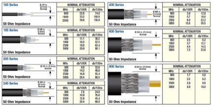 Types of coax-cable with rf attenuator calculator, line loss calculator form includes an antenna gain calculator. This coax loss calculator can help you on choosing the right cable for your antenna sysmte.
 -
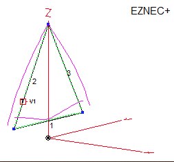
 Small antenna, what causes loss and how to increase radiation resistance in small antennas., A description of loss and radiation resistance.
 -
 Discussion at eham about wire size used in wire antennas, and how it affects the gain of the antenna
 -
 The **136kHz Vertical Antenna** at G3YMC employs a Butternut HF2V structure, standing 10m tall. It integrates a 6.5mH loading coil to achieve resonance, with a matching transformer for impedance adjustment. The antenna's configuration includes top loading via a 12m horizontal wire, enhancing capacitive impedance. Initial measurements indicated a high impedance of around 300 ohms, necessitating a transformer for a 50-ohm match. Despite challenges with ground losses, the vertical antenna has shown improved performance in specific directions, filling nulls present in the previous loop antenna setup. The tuning remains broad, with variations due to environmental factors affecting the matching. Ongoing adjustments and comparisons with the loop antenna will continue to refine its effectiveness.
 -
 How do two-wire reversible direction Beverages work, an excellent document that explains fundamentals of beverage antennas. This article details the design and performance of a reversible beverage antenna. Leveraging orthogonality between common mode and differential mode currents on a 2-wire line, this antenna facilitates independent reception from both ends. While common mode signals arrive and are summed on a transformer's secondary for common mode reception, differential mode signals induce anti-phase currents, providing individual reception. Various measurements explore impedance, transmission loss, and F/B ratio, highlighting the antenna's effectiveness and areas for improvement. Notably, increasing the antenna's height significantly improved performance.
 -
 How manage and quantify ground loss in vertically-polarized antennas by VE3VN
 -
 The article, "Using 75 Ohm CATV Coaxial Cable," details methods for employing readily available 75-ohm CATV hardline in standard 50-ohm amateur radio setups. It addresses the inherent impedance mismatch and practical considerations, such as connector compatibility, for hams seeking cost-effective, low-loss feedline solutions. The resource specifically contrasts common 50-ohm cables like RG-8, RG213, and _LMR-400_ with 75-ohm hardline, highlighting the latter's lower loss characteristics, particularly at VHF and UHF frequencies. It explores two primary approaches to manage the impedance difference: direct connection with an acceptable SWR compromise and precise impedance transformation. The direct connection method acknowledges that a perfect 1:1 SWR is not always critical, especially when using low-loss coax. For impedance transformation, the article explains the use of half-wavelength sections of coax to reflect the antenna's 50-ohm impedance back to the transmitter, noting its single-frequency effectiveness. It also briefly mentions transformer designs using toroid cores and a technique involving two 1/12 wavelength sections of feedline for broader bandwidth. The content further clarifies the concept of _velocity factor_ for calculating electrical versus physical cable lengths, providing a generic formula for precise length determination. It notes that while half-wave matching is practical for 10 meters and above, it can result in excessively long runs for lower bands like 160 meters, potentially adding **250 feet** of cable. The article also mentions achieving a usable bandwidth of 28.000 MHz up to at least **28.8 MHz** on 10 meters with specific transformation techniques.
 -
 1.5 dB of matched line loss can be calculated for a given transmission line using this online tool, which employs a model calibrated from empirical data. The calculator allows radio amateurs to input specific transmission line types, such as _RG-8_ or _RG-58_, and then determine the expected signal attenuation. This is crucial for optimizing antenna system efficiency and understanding power delivery to the radiating element, especially for HF and VHF operations where feedline losses can significantly impact performance. Beyond matched loss, the calculator also provides an estimate for mismatched loss if the Standing Wave Ratio (SWR) is specified. This feature helps operators quantify the additional power loss due to impedance discontinuities between the transceiver, feedline, and antenna, which is a common concern in amateur radio installations. Accurate loss calculations are vital for effective station design and for predicting actual radiated power. The tool's utility extends to various operating scenarios, from fixed station setups to portable deployments, aiding in the selection of appropriate feedline lengths and types to minimize signal degradation. Understanding these losses is a fundamental aspect of maximizing the effectiveness of any amateur radio antenna system.
 -
 K1JJ presents a compilation of insights regarding vertical radial ground systems, specifically applied to 160m vertical arrays. The resource details 19 distinct observations and recommendations, emphasizing that ground radials primarily reduce ground losses rather than influencing pattern formation. It explains that RF current flows inefficiently through average soil, necessitating copper radials to create a low-resistance path back to the antenna base. The content suggests that **50-60 radials** are generally sufficient to achieve optimal efficiency, with diminishing returns beyond that number, and that radials should be laid on the surface for best performance. The discussion also addresses practical aspects such as wire gauge, installation techniques using 'U' shaped staples, and methods for connecting radials in multi-element arrays. It highlights the importance of radial length, stating that 1/4 wave radials are a crucial minimum, and that for 160m, radials should be at least _100 feet_ long. The resource critically examines the efficacy of elevated radials versus ground radials, noting that while a few elevated radials may suffice for VHF, HF applications, particularly on 160m, require extensive ground radial systems to efficiently collect RF currents in the near field. It also touches on the impact of radial systems on parasitic elements and the significance of symmetrical radial patterns for minimizing losses. Further practical advice includes wire type recommendations, proper soldering and weatherproofing techniques for radial connections, and considerations for integrating steel towers into the ground system. The author shares personal experience with installing 60 quarter-wave and half-wave radials under each of three in-line verticals, expressing satisfaction with the results.
 -
 Examines Radio Frequency Systems (RFS), a manufacturer specializing in high-performance cable solutions for diverse communication infrastructures. The company, with over 120 years of heritage, focuses on designing and producing robust, long-life connectivity systems, including _low loss foam dielectric RF cable_ and _premium radiating cable_. RFS's product range supports critical applications in cellular networks, microwave antenna systems, and specialized installations within buildings and tunnels. The resource highlights RFS's commitment to innovation, addressing emerging industry standards like _FRMCS_ for railway communication and advanced fiber solutions for data centers. It also details the company's manufacturing capabilities in Hannover, Germany, emphasizing the quality and reliability associated with _Made in Germany_ products. The content covers various connectivity landscapes, from urban solutions for connected cities to private 5G credentials and future plans. Specific product categories include _fiber, power & hybrid cable_, and _low loss high power air dielectric RF cable_, showcasing their broad portfolio for complex RF environments.
 -
 Article on antenna feed impedance and the importance of matching RF andtennas to feeders, including notes on Radiation resistance, loss resistance, and efficiency are also detailed.
 -
 Details Amphenol's extensive product line, encompassing electrical, electronic, and fiber optic connectors, alongside coaxial and flat-ribbon cable solutions. The company designs, manufactures, and markets these interconnect systems globally, serving various communication network requirements. Their offerings support end-to-end connectivity, crucial for modern broadband infrastructure. Emphasizes the company's role as a major provider of components vital for reliable signal transmission in diverse applications. Products like _LMR(R) coaxial cables_ and various _RF connectors_ are essential for amateur radio installations, ensuring low loss and robust connections for antennas and transceivers. The focus on high-performance interconnects directly benefits hams constructing or upgrading their stations. Amphenol's broad portfolio includes specialized connectors and cable assemblies, meeting rigorous technical specifications for both commercial and amateur radio use.
 -
 Operating an amateur radio club, VE2CEV details its activities, including regular meetings and a significant project involving the construction of a **satellite ground station**. The resource outlines the project's inception, team formation, equipment acquisition, and the physical installation of antennas and rotator systems. It specifically mentions the use of a dual-axis AZ/EL rotator and antennas for VHF, UHF, and SHF (2 meters, 70 centimeters, and 13 centimeters), along with the strategic use of **Heliax cables** to minimize RF signal loss. The club also provides information on its interconnected repeater network covering southwestern Montérégie. The content highlights the practical application of the satellite station for communicating via amateur satellites and the International Space Station (ISS). It details the collaborative effort of members in securing a powerful Linux server, negotiating antenna installation with local authorities, and the precise alignment of antennas. The club emphasizes its role in guiding new amateurs, offering demonstrations, and potentially organizing courses, indicating a focus on community engagement and technical education within the amateur radio hobby.
 -
 TIM-CO, an authorized distributor, offers a range of electronic components crucial for various applications, including amateur radio station builds. Their inventory focuses on **connectors**, both commercial and military-grade, which are essential for robust and reliable interconnections in radio equipment and antenna systems. This includes a variety of types suitable for RF applications, ensuring signal integrity. Beyond connectors, TIM-CO provides passive and electromechanical components, fundamental building blocks for any radio circuit or control system. These components are vital for constructing filters, impedance matching networks, and power distribution systems within a shack. Their selection supports both new construction and repair of existing gear. Additionally, the company supplies **RF-coax cable assemblies**, pre-fabricated solutions that save time and ensure proper termination for feedlines and inter-component connections. These assemblies are critical for minimizing signal loss and maintaining impedance matching from the transceiver to the antenna.