Search results
Query: mic filter
Links: 60 | Categories: 0
-
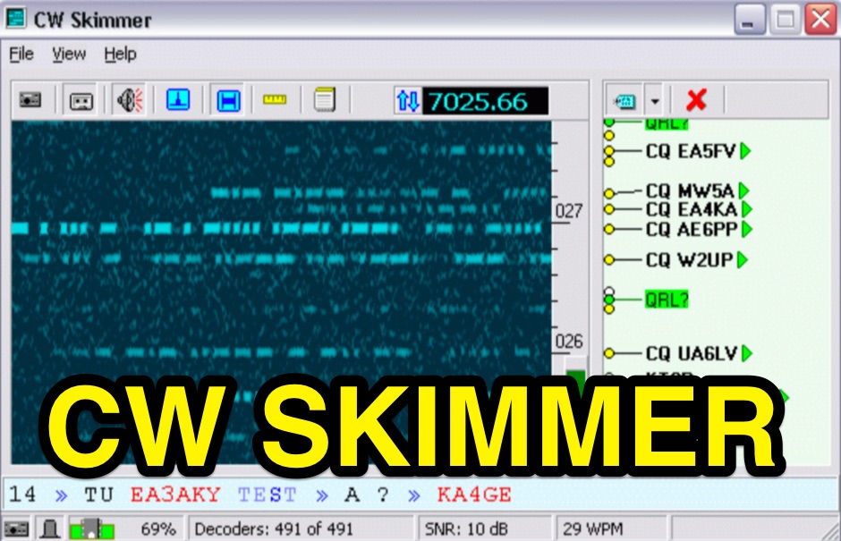 CW Skimmer 2.1 employs a high-sensitivity CW decoding algorithm based on Bayesian statistics, enabling simultaneous decoding of up to 700 CW signals within a receiver's passband on a 3-GHz P4 system when paired with a wideband receiver. The software features a fast waterfall display with sufficient resolution for visual Morse Code interpretation, automatically extracting and labeling callsigns on the waterfall traces. Extracted callsigns are exported as DX cluster spots via an integrated Telnet cluster server. The application includes a DSP processor with a noise blanker, AGC, and a variable-bandwidth CW filter, alongside an I/Q Recorder and player. It supports both 3 kHz radio passbands and wideband SDR receivers like SoftRock, RF Space SDR-IQ/SDR-14, SRL QuickSilver (QS1R), HPSDR Mercury, and Microtelecom Perseus. System requirements specify Windows XP/7/8/10 (32-bit or 64-bit), a Pentium-4 2.5 GHz for wideband operation or 1 GHz for 3-kHz radios, a COM port for CAT control, and a stereo sound card supporting 48 kHz sampling. It integrates with Elecraft KX3, Icom IC-7300/IC-7610, and Flex 6000 series radios, with documentation available for various setup configurations.
 -
 The most flexible and powerful Microwave and RF Filter and Multiplexer Design Software. Download Filpro-student.zip
 -
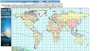 DXMaps.com presents a dynamic, real-time mapping service for amateur radio DX spots, integrating data from traditional DX clusters, _PSK Reporter_, and WSPR networks. The platform visually plots global QSO and SWL activity, enabling users to observe propagation conditions across various bands, from 2200m to >450 MHz. It offers distinct overlays such as the magnetic equator, gray line, moon footprint for EME, and VOACAP propagation predictions, providing a comprehensive view of radio wave behavior. The service allows granular filtering of displayed spots, including options to show only DX-Cluster data, PSK Reporter activity, or WSPR signals. Users can refine the map view by selecting specific bands (e.g., 160m, 20m, 6m, 2m), limiting spots to the last 15 minutes, or displaying only contacts exceeding **2600 km**. Additional features include the ability to toggle grid squares, aurora forecasts, and various amateur radio zones (CQ, ITU). Distinctively, the resource updates automatically every minute, ensuring current propagation intelligence without manual refresh. It also supports specialized views for EME, ionospheric scatter, and aircraft scatter, alongside FM DX and APRS activity. The platform emphasizes the importance of accurate locator information in DX spots to enhance data quality and offers a user manual and FAQ for guidance.
 -
 Stacking and phasing HF and 6m arrays antenna switches and contesting devices. Custom low band antenna arrays, bandpass filters,commercial/Mil STd filters,microwave components, commercial broadcast filters.
 -
 Demonstrates the construction of a **homebrew spectrum analyzer** designed by Wes Hayward, W7ZOI, and Terry White, K7TAU, enabling radio amateurs to build a capable test instrument without significant expense. The resource details a _double-conversion superheterodyne_ circuit, employing intermediate frequencies of 110 MHz and 10 MHz, and covers essential blocks such as the time base, logarithmic amplifier, resolution filters, and local oscillators. It highlights the use of hybrid and monolithic ICs, including mixers, amplifiers, and VCOs, to simplify construction while maintaining performance. The design supports useful measurements in the 50 kHz to 70 MHz range, with methods outlined for extending capabilities into VHF and UHF. The authors emphasize that this analyzer, while simple to build, is intended for serious measurements, requiring careful control of signal levels to avoid spurious responses. It uses an oscilloscope for display, with specific instructions for calibration and adjustment of various stages, including the log amplifier and IF gain. The guide provides detailed schematics and component lists for each section, such as the 110 MHz triple-tuned band-pass filter, which achieved **90 dB** image rejection, a significant improvement over double-tuned circuits. Practical advice on alignment and troubleshooting is included, drawing on the authors' extensive experience in RF circuit design.
 -
 Over 75 years of engineering expertise underpins Bird Electronic's offerings in RF power measurement, critical for maintaining peak performance in amateur radio stations and professional communication systems. The company specializes in a range of test equipment, including wattmeters, SWR meters, and antenna analyzers, essential for optimizing antenna systems and ensuring efficient power transfer. Their product line extends to various RF components such as filters, cables, and connectors, all designed to meet stringent technical specifications for reliability and accuracy across diverse frequency bands. Bird Electronic's instruments, like the _Bird 43_ Thruline Wattmeter, are widely recognized for their robust construction and precise measurement capabilities, providing hams with confidence in their station's operational parameters. These tools enable accurate assessment of forward and reflected power, SWR, and modulation characteristics, which are vital for troubleshooting and maximizing radiated power. The company's commitment to innovation ensures that its products remain relevant for modern RF challenges, from HF through microwave applications, supporting both traditional analog and advanced digital modes.
 -
 HotPaw MorseDecoder, an iOS application, provides real-time translation of Morse Code audio signals into plain text, leveraging the device's microphone or headset input. It incorporates a DSP narrow-band audio filter, adjustable from 300 to 2400 Hz, to mitigate background noise and QRM, enhancing signal clarity for decoding. The application offers both an automatic decoding mode and manual controls for fine-tuning parameters such as audio filter frequency, WPM dot/dash speed, noise threshold, and Farnsworth timing. The WPM detection automatically adapts from 8 to 40 WPM, with a QRQ High Speed mode extending this range to 30-80 WPM for faster code. A built-in spectrogram aids in identifying the precise audio frequency of the CW tones. User feedback indicates effective performance with various transceivers like the Yaesu FT-857 and Icom IC-R8600, particularly when manual settings are optimized. The app's ability to visually tune stations within the passband and decode speeds beyond an operator's manual capability has proven beneficial during contests and general QRP operation.
 -
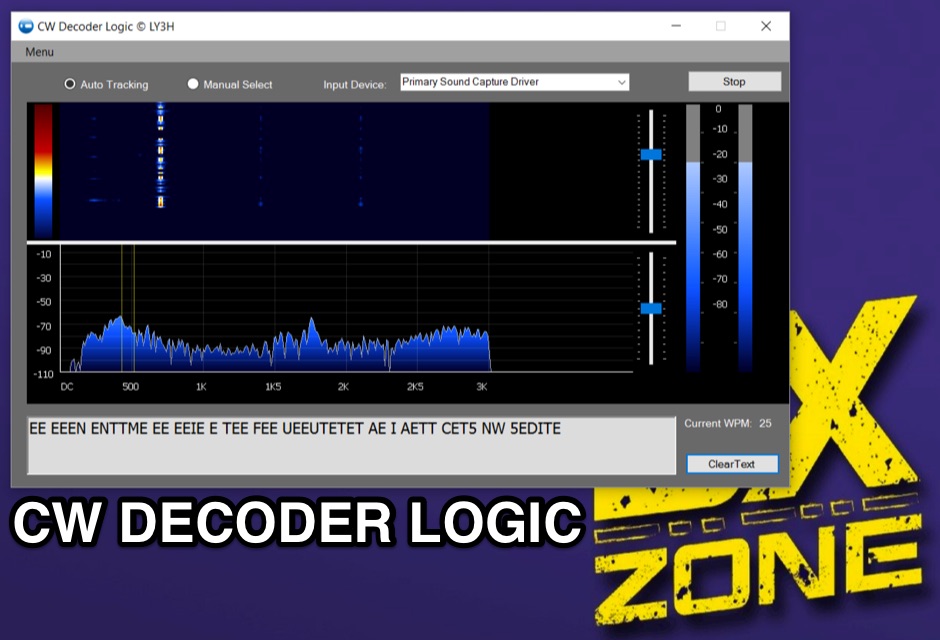 Demonstrates CW Decoder Logic, a freeware application for Windows Vista SP2, 7, 8, and 10, designed to decode Morse code signals. The software incorporates an optimized 80 Hz DSP filter, enabling reception of CW signals across a speed range of 5 to 60 WPM. Key features include automatic signal tracking within a 3 KHz range, real-time speed detection, and an auto squelch function, enhancing decoder sensitivity and accuracy. The application provides station selection directly on a waterfall display and includes a "Tips" feature for word annotations. It supports sending decoded text to external logging software via UDP protocol, with a logger source code example provided for developers. Configuration options allow users to set speed limitations and customize interface elements. Released initially on October 17, 2016, with subsequent updates, the program requires Microsoft .NET Framework 4.5 or higher. Changelogs detail improvements such as increased program stability, code optimizations for speed, and fixes for display issues across different Windows versions.
 -
 Amateur radio accessories, power supplies, tvi filters, speakers, microphones, swr meters, preamplifiers, switches, cable and connectors,
 -
 The RigPix database entry provides a comprehensive technical overview of the Icom IC-746 amateur HF/VHF transceiver, detailing its operational parameters and physical characteristics. It specifies the transmit frequency ranges across 10-160 meters plus WARC bands, 50-54 MHz, and 144-146/148 MHz, alongside receive coverage from 0.03-60 MHz and 108-174 MHz. The resource outlines supported modes including AM, FM, SSB, CW, and RTTY, noting a tuning step resolution down to 1 Hz and a frequency stability of ±5 ppm. Key electrical specifications are presented, such as a 13.8 VDC power supply requirement, current drain figures for RX (1.8-2 A) and TX (Max 20 A), and RF output power ranging from 5-40 W for AM and 5-100 W for FM, SSB (PEP), and CW. The entry details the triple conversion superheterodyne receiver system, listing IF frequencies at 69.01 MHz, 9.01 MHz, and 455 KHz, along with sensitivity ratings for various modes and bands. Transmitter section specifics include modulation systems and spurious emission levels. Additional features like a built-in auto ATU, electronic keyer, simple spectrum scope, DSP, and CI-V computer control are noted. The page also lists related documents, modifications, and an extensive array of optional accessories, including various filters, microphones, and external tuners, providing a complete profile of the IC-746.
 -
 The Adonis Electric Co., Ltd. catalog details a range of amateur radio microphones, including mobile, desktop, and bike-specific models, alongside essential accessories. Featured products include the _FX-6_ flexible microphone and various interconnecting cables designed for seamless integration with transceivers from Icom, Yaesu, and Kenwood. The catalog also presents specialized items like microphone selectors, alternator noise filters, and peripherals such as voice memory units and double VOX controllers, enhancing operational flexibility for hams. These products are engineered to improve audio clarity and operational convenience for amateur radio operators, particularly in mobile and fixed station environments. The inclusion of conversion codes ensures compatibility across major transceiver brands, simplifying setup. The alternator noise filter addresses common mobile RFI issues, contributing to cleaner signal reception and transmission, which is crucial for effective DXing and contesting.
 -
 Constructing a functional spectrum analyzer for the 0-100 MHz range presents a significant challenge for radio amateurs, often requiring specialized components and careful calibration. This project details a homebrew spectrum analyzer design utilizing common integrated circuits like the _SA605D_ FM receiver IC and _MAR-6_ MMIC amplifiers, aiming for a cost-effective solution. The design incorporates a low-pass filter, RF amplification, a voltage-controlled oscillator (VCO) for downconversion, and multiple IF stages at 150 MHz and 10.7 MHz, with a resolution bandwidth (RBW) of 15 kHz. Critical components such as the _SBL-1_ mixer and varicap diodes are specified, alongside instructions for winding inductors and tuning filters. The analyzer's performance is discussed in terms of input level limitations, specifically the 1dB-compression point and third-order intercept point, to ensure accurate measurements and prevent component damage. The _SA605D_'s logarithmic Received Signal Strength Indicator (RSSI) output serves as the detector, driving the Y-input of an oscilloscope, while a _TL084_ op-amp generates the sweep signal for the X-input. Potential enhancements include adding a step attenuator, improving front-end filtering, and implementing switchable IF filters for variable RBW, allowing for greater versatility in analyzing RF signals.
 -
 HD Communications Corp specializes in **RF and microwave amplifiers** engineered for demanding communication, defense, and industrial applications. Their product line includes precision-built, high-power solutions, along with RF connectors, filters, HF cables, and various accessories. The company also supplies tower hardware, valves, and tubes, catering to a broad spectrum of radio frequency infrastructure needs. Beyond amplifiers, HD Communications offers a range of **RF filters**, including low-pass filters, antenna filters, and solutions for RFI/TVI mitigation. Their inventory encompasses essential components like coaxial cable and various connector types, supporting both amateur radio and professional installations. The company operates as a manufacturer and vendor, providing direct sales of its specialized RF products.
 -
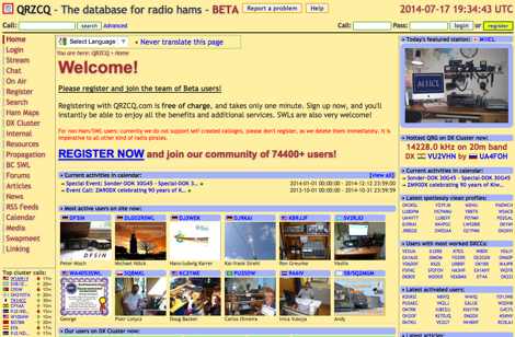 QRZCQ.com provides a centralized online platform for amateur radio operators, integrating a global callsign database with DX Cluster functionality. The service features real-time DX spotting, filtering capabilities for specific bands (e.g., 160m, 80m, 40m, 20m, 15m, 10m), and specialized filters for awards like IOTA, SOTA, WWFF, and QRP activity. It also includes a logbook, QSL manager lookup, contest calendar, and various ham radio articles and news feeds, supporting a wide range of operating activities and information retrieval. The platform aggregates data from multiple sources, offering a dynamic view of on-air activity and callsign information. Users can register for free to access additional services, including a personal logbook, buddy lists, and chat features, fostering community interaction among over 198,600 registered users. The DX Cluster displays recent spots with frequency, DX call, spotter, and remarks, covering bands from VLF to VHF. Beyond DX spotting, the site provides resources such as repeater directories, propagation information, and a swapmeet, making it a multi-faceted tool for both casual browsing and serious DXing or contesting. The service also highlights active users, latest news, articles, and videos, keeping the content fresh and relevant.
 -
 One specific challenge in the KazShack, operating Single Operator Two Radios (SO2R), involved sharing a K9AY receive antenna between two transceivers without direct RF connection or manual feedline swapping. The solution, detailed in this project, adapts the **W3LPL RX bandpass filter** design to split 160m and 80m signals, feeding them to separate radio inputs while maintaining isolation. This approach also addresses the issue of strong broadcast band interference from a nearby 50KW WPTF transmitter on 680kc. The construction utilizes T-50-3 toroids and NP0 ceramic capacitors, built in a "dead bug" style on copper clad board. Each band's filter coils are identical and resonated to the desired frequency using an MFJ-259 antenna analyzer. A single DPDT relay, controlled by a remote toggle switch mounted on an aluminum panel, facilitates quick band switching between radios, simplifying low-band operations. While some signal loss is noted, the expected lower noise levels from the receive antenna are anticipated to compensate, potentially reducing the need for constant volume adjustments during toggling between transmit and receive antennas.
 -
 The QLF filter is a microprocessor based interface designed to go between a standard Morse code key and a radio transmitter
 -
 Leading supplier of low and high frequency electronic filter design products for the design of wireless telecommunications equipment, semiconductors and more
 -
 A re-usable control & computing platform for antenna measurement, PSK31 digital modems, audio filtering, signal source & VFO, memory keyer by AMQRP
 -
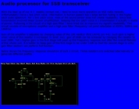 This circuit consists of microphone amplifier and a high pass filter. Suitable to improve signal readability.
 -
 The Yaesu FT-1000MP Mark-V, introduced at Dayton 2000 Hamvention, features a higher RF power of **200 W PEP** and a Class-A amplification SSB mode at 75 W. Key enhancements include an _Interlocked Digital/Analog Bandwidth Tracking system (IDBT)_, a Variable Front-End Filter (VRF) preselector, and improved ergonomics, notably a multi-function shuttle jog dial. This model, a successor to the 1996 FT-1000 and FT-1000MP, was designed to compete with high-end transceivers, despite its retail price of $4200 initially. The transceiver's physical dimensions are 406 x 135 x 348 mm (16 x 5.3 x 13.7 inches) with a weight of 14 kg (31 lbs), making it substantial. Its rear panel offers over 20 connections, including power, external DSP speaker, BAND DATA I/O, ALC, and multiple interface jacks for DVS-2, Packet, and RTTY. The unit also provides two keyer inputs, a DB9M serial interface for CAT, and two PL female antenna connectors, plus additional receive antenna jacks. Despite its advanced internal architecture, including two independent receivers with their own IF filters and AGC loops, the display technology, utilizing fluorescent discharge rather than LCD, contributes to an older aesthetic. The control panel is extensive, featuring 92 knobs and buttons, alongside numerous LED indicators for various modes and functions.
 -
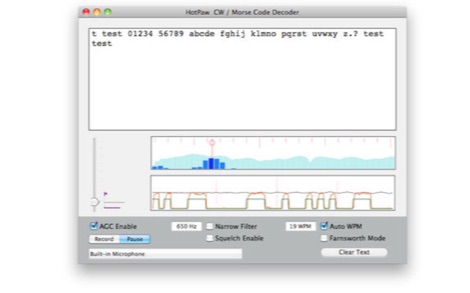 The HotPaw Morse Code Decoder application for macOS processes audio input to transcribe Morse code characters into text. It presents both an audio spectrum graph and a tone amplitude graph, which aid in configuring a narrow band audio filter. Operators can set the audio filter for tone frequencies between 400 and 1600 Hz, optimizing reception for various CW signals. The software offers user-configurable settings, including WPM dot/dash speed detection, a noise threshold level, and the option to use Farnsworth timing for inter-character spacing. The Morse code WPM detection automatically adapts from approximately 8 to 40 WPM, with a lock feature for the estimated speed. A High Speed WPM Mode is available for code speeds ranging from 40 to 80 WPM, catering to faster CW operators. The application's decoding performance is influenced by signal level, signal-to-noise ratio, frequency and WPM stability, keying quality, and proper configuration, with an initial learning phase required for WPM estimation to stabilize. An external microphone or line-in may be necessary for optimal performance on some MacBook models to mitigate fan noise or room reverberations. Version 1.4.4, updated on November 11, 2021, includes compatibility improvements for newer macOS releases. The developer, Ronald Nicholson of HotPaw Productions, does not collect any user data from the application.
 -
 Australia's largest range of Electronic Kits & Components In Stock for the Radio Experimenter, ATV, microwaves, HF Band pass filters
 -
 A 200 kHz bandwidth digital transmission system for image transfer in the Amateur Service is under development, specifically targeting VHF allocations. John B. Stephensen, KD6OZH, leads this project under an FCC Special Temporary Authority (STA) valid until September 10, 2006, authorizing emissions up to 200 kHz bandwidth in the 50.3-50.8 MHz segment. Current regulations typically limit bandwidths to 20 kHz on VHF amateur bands, making this STA crucial for testing wideband digital modes. The modem, a modified **OFDM** (Orthogonal Frequency Division Multiplexed) unit, was initially tested on the 70-cm band. It splits a high-rate data stream into multiple low-rate subcarriers to mitigate multipath echoes. The system uses a DCP-1 card with a Xilinx XC3S400 FPGA and Oki Semiconductor ML67Q5003 microcontroller. The transmitter, located at 36d 46m 30s N, 119d 46m 22s W, generates 150 WPEP into an 8 dBi gain vertical antenna, while the mobile receiver uses a Ham-stick. Three data formats for 50, 100, and 200 kHz channels are being tested, with encoded data rates of 96, 192, and 384 kbps. Verilog code for the VHF OFDM modem is 95% simulated, with modifications from the UHF version including increased filter coefficient precision and a change from Ungerboeck **TCM** to BICM for improved performance over fading paths. Final tests will involve one-way over-the-air measurements of bit error rates and coverage area.
 -
 A DIY Automatic Band Decoder (ABD) project, designed for dual-radio operation, addresses the common challenge of integrating band data with older transceivers lacking dedicated outputs. This particular build utilizes an AVR AT90S8515 microcontroller and a 16x2 Liquid Crystal Display (LCD) to provide band information, specifically targeting Kenwood rigs via a computer's LPT port. The design aims for cost-effectiveness while maintaining functionality, offering a solution for hams seeking to add automatic band switching capabilities to their station without significant expense. The project outlines the core components required, including the microcontroller, LCD, and an enclosure, noting that the Printed Circuit Board (PCB) fabrication and AVR programming might present challenges for some builders. It details the input requirements, such as a four-pin input and PTT for each radio, along with a 13.8V DC power supply. The decoder provides 2x6 outputs capable of sinking 500mA, suitable for controlling external devices like antenna switches or filters. Despite the original unit being damaged by a lightning strike in 2004, the author confirms its successful operation prior to the incident and mentions plans for a revised version. The resource includes a schematic in PDF format and images of the finished PCB and assembled unit, demonstrating the practical implementation of the design.
 -
 Optimizing weak signal reception on the HF bands, particularly in the presence of strong local QRM, often necessitates specialized receiving antenna systems. This resource details the _HI-Z Antennas_ product line, focusing on phased vertical arrays designed for superior noise rejection and directivity. It covers components such as the 4-Square and 8-Element array controllers, which allow for rapid switching of receive patterns, and dedicated low-noise preamplifiers to improve system sensitivity. The site also presents various bandpass filters, crucial for mitigating out-of-band interference and enhancing the dynamic range of the receiver. The HI-Z systems are engineered to provide significant front-to-back and side rejection, often yielding **20-30 dB** of attenuation to unwanted signals, which is critical for DXing and contesting. Users can achieve a notable reduction in local noise, allowing for the discernment of signals that would otherwise be buried. The array controllers facilitate quick pattern changes, enabling operators to null out interference or peak weak signals from distant stations, effectively extending the reach of their receive capabilities by improving the signal-to-noise ratio.
 -
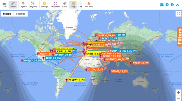 Monitoring real-time amateur radio activity is essential for DXers and contesters seeking rare contacts or tracking propagation. This online service aggregates DX spots from various **DX Cluster** networks, presenting them visually on a world map. Users can observe new spots as they appear, facilitating quick identification of active stations and potential openings. The platform offers filtering capabilities, allowing operators to narrow down displayed spots by specific bands such as 160m, 80m, 40m, 20m, 10m, and even VHF/UHF segments like 70cm and 23cm. Further refinement is possible by selecting the source continent of the spotter or the continent of the DX station, which assists in strategic operating. The service also includes a "Hot Now" list, highlighting currently active stations with recent spots. This dynamic display supports informed decision-making for pursuing **DX contacts** across different bands and geographical regions.
 -
 Operating the _Icom IC-746_ HF/VHF transceiver often presents specific technical questions, and this resource compiles a comprehensive Frequently Asked Questions (FAQ) document in an ASCII text format. It details common inquiries and solutions related to the rig's functionality, accessories, and potential modifications. The content is structured into distinct sections addressing general information, power supplies, antennas, microphones, keyers, amplifiers, TNC integration, and optional IF filters. The FAQ provides practical guidance on topics such as configuring the internal automatic antenna tuning unit (ATU), selecting appropriate power supplies, and understanding microphone pin-outs. It also delves into advanced subjects like computer control via CI-V, wiring for PSK31 operation, and troubleshooting common issues like low S-meter readings on 2m FM or loose tuning shafts. Specific questions cover the installation of optional IF filters, comparing Inrad versus Icom filters, and optimizing filter combinations for various modes. Furthermore, the document outlines various hardware and firmware modifications, including those for increasing monitor volume, replacing LCD driver transistors, and implementing a "poor man's TCXO." It even touches upon untested modifications, such as replacing PIN diodes in the demodulator. The FAQ also lists manual errata and discrepancies, offering a robust knowledge base for IC-746 owners seeking to optimize their station or resolve operational challenges.
 -
 The Reverse Beacon Network (RBN) graph presents a dynamic visualization of amateur radio spots, specifically tracking CW, BPSK, and RTTY signals over the last 15 minutes. Users can filter these real-time spots by DX continent, spotter continent, and individual frequency bands, including **160m through 70cm**. The interface also offers a bandwidth reduction option, which is particularly useful for operators with limited internet connectivity. This resource provides a unique perspective on propagation conditions and station performance by aggregating data from various _Reverse Beacon Network_ nodes. It automatically refreshes every 10 seconds, ensuring that the displayed information is current and relevant for active DXers and contesters. The graph's Y-axis represents time, with each spot indicating activity within a one-minute interval. Beyond the primary RBN graph, the platform also features dedicated maps for both DXCluster and RBN data, including azimuthal projections. An additional FT8 graph is available, though noted as being under construction, indicating ongoing development to expand its utility for digital mode enthusiasts. The system was developed by HA8TKS, with the initial concept attributed to CT1BOH.
 -
 The _Sci.Electronics FAQ: Repair: RFI/EMI Info_ document, authored by Daniel 9V1ZV, provides a detailed analysis of computer-generated RFI/EMI, focusing on its impact on radio reception. It identifies common RFI sources such as CPU clock rates (e.g., 4.77 MHz to 80 MHz), video card oscillators (e.g., 14.316 MHz), and even keyboard microprocessors, all of which generate square-wave harmonics across HF and L-VHF regions. The resource outlines a systematic procedure for pinpointing RFI origins, including disconnecting peripherals and using a portable AM/SW receiver with a ferrite rod antenna to localize strong interference sources. The document categorizes RFI mitigation into shielding, filtering, and design problems, offering practical solutions for each. It recommends applying conductive sprays like _EMI-LAC_ or _EMV-LACK_ to plastic casings of radios, monitors, and CPUs to create effective Faraday cages, emphasizing proper grounding and avoiding short circuits. For filtering, the guide suggests using line filters, ferrite beads, and toroids on power and data lines, and small value capacitors (e.g., 0.01 uF for serial/parallel, 100 pF for video) to shunt RFI to ground. It also discusses the use of bandpass, high-pass, low-pass, and notch filters on the receiver front-end or antenna feed to combat specific in-band noise.
 -
 This site is dedicated to design and analysis of micro- and millimeter wave filters from 0.5 to above 100 GHz.
 -
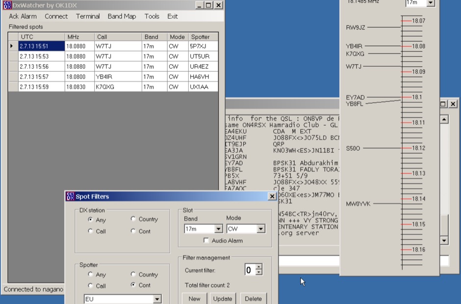 Demonstrates a specialized DX cluster monitoring application, _DxWatcher_, designed for Windows environments. It processes DX spots received via Telnet/Internet, presenting them in a filtered table and a dynamic bandmap. The software integrates with transceivers, specifically the FT-2000, to read VFO frequency and enable one-click tuning to spotted stations. _DxWatcher_ version 1.0.3.0, released on 13 June 2020, includes minor bugfixes and improvements such as enhanced recovery from suspend mode. Key features include configurable bandmap position and size, automatic opening, and bolding of spots received within the last **10 minutes**. The application utilizes the standard _ctry.dat_ file for DXCC country analysis, allowing users to update it for current DXCC status. Source code, developed in C# with MS Visual Studio 2008, is freely available, encouraging modification and sharing while requesting retention of the original author's callsign.
 -
 A synthesized 2.3 GHz Amateur Television (ATV) transmitter design, conceived by Ian G6TVJ, is presented, targeting broadcast-quality video performance on the 13cm band and extending up to 2.6 GHz. The core of the design utilizes a commercial Z-comm Voltage Controlled Oscillator (VCO) that tunes from 2.2-2.7 GHz, providing a +10 dBm output and simplifying RF alignment. This VCO's stability, originally intended for narrowband applications, readily accepts high-frequency video modulation, contributing to the transmitter's robust performance. The exciter stage, incorporating a Mini Circuits VNA 25 MMIC amplifier, boosts the signal to +16dBm, while a Plessey SP4982 prescaler divides the output frequency for the synthesizer. The synthesizer employs a Motorola MC145151 CMOS parallel IC, favored over the common Plessey SP5060 for its superior video modulation characteristics and ease of programming without microprocessors. This choice addresses issues like LF tilt and distorted field syncs often seen with SP5060 designs, particularly when operating through repeaters or over long distances. The MC145151 divides the signal further, enabling precise frequency stepping, with programming handled by EPROMs for channel selection and LED display. The loop filter network, critical for video integrity, was developed through experimentation to prevent the PLL from reacting to video modulation, ensuring a clean transmitted picture. The transmitter incorporates a Down East Microwave commercial power amplifier module, delivering approximately 1.6W output, driven by the exciter through a 3dB attenuator. Construction involves surface-mount SHF components on micro-strip lines etched onto double-sided fiberglass board, housed within a tinplate box. The design boasts no AC coupling in the video path, preserving low-frequency response, a common failing in other ATV transmitters. Performance tests with a 50Hz square wave revealed no LF distortion, and a calibrated "Pulse & Bar" signal showed a near 100% HF response, demonstrating its capability for high-quality ATV transmissions.
 -
 Broadband instruments, R and microwave components and filters, field analyzers, spectrum analyzers
 -
 Amplifiers, filters, attenuators, mixers, PLL, switches and frequency dividers, signal generators, power detectors, transimpedance amplifiers, variable gain amplifiers and more
 -
 An economical way of building an SSB filter. The circuit is for a filter with a 6 DB band width of roughly 2.2 KHz.
 -
 The Kenwood TS-870S HF transceiver features two state-of-the-art 24-bit 20 MIPS DSP chips, providing over 100dB out-of-passband attenuation and CW bandwidth adjustable to 50 Hz. It operates across 160-10 meters with 100 watts output, incorporating digital filtering, a beat canceller, and 100 memory channels. The radio also includes a transmit equalizer, RX antenna input, and a K1 Logic Keyer, enhancing signal processing and operational flexibility for amateur radio operators. Advanced capabilities include IF stage DSP, dual noise reduction, and an auto notch filter, all contributing to superior signal reception and clarity. The TS-870S offers a variable AGC, voice equalizer, and an RS-232C port for computer control, with Windows™ software supplied. Its built-in automatic antenna tuner functions on all bands for both transmit and receive modes, streamlining station setup and operation. Available accessories such as the DRU-3A digital recording unit, SO-2 high stability crystal oscillator, and VS-2 voice synthesizer option further extend the transceiver's utility. The unit requires 13.8 VDC at 20.5 Amps and is supplied with an MC-43S hand microphone, making it a comprehensive station component.
 -
 Cobham Microwave has a long term experience in Microwave Systems and Components. Their five areas of capabilities are Systems and Components: Diodes & Modules, Ferrite Devices, RF Filters, and Waveguides.
 -
 Constructing a high-performance RF spectrum analyzer up to 1000 MHz requires careful attention to component selection, shielding, and circuit isolation. This resource details a project that improves upon the _Spectrum Analyzer for the Radio Amateur_ design by Wes Hayward (W7ZOI) and Terry White (K7TAU), incorporating ideas from Scotty Sprowls' project, particularly his 1013.3 MHz IF bandpass cavity filter. The analyzer utilizes a Mini-Circuits SRA-11 mixer with a sweeping local oscillator from 1013 to 2013 MHz, feeding into a 4-pole copper pipe cavity filter. The design employs a second SRA-11 mixer with a fixed 1024 MHz LO to produce a 10.7 MHz final IF. This signal then passes through narrowband resolution filters and is processed by Analog Devices AD603 and AD8307 ICs for IF amplification and logarithmic detection, driving an oscilloscope in X/Y mode. The project emphasizes modular construction, using salvaged components and double-sided FR4 material for PCBs, with critical notes on minimizing spurious images through effective shielding and proper voltage regulation for each module. Key components include a Z-Communications V585ME48 VCO for the first LO and a Z-Comm V583ME01 VCO controlled by a Motorola MC145151 PLL for the second LO. An optional Hittite HMC307 step attenuator and K&L 5L121-1000/T5000-O/O low-pass filter manage RF input. Tuning procedures for the 10.7 MHz IF resolution filter are also detailed, showing before-and-after spectrum views.
 -
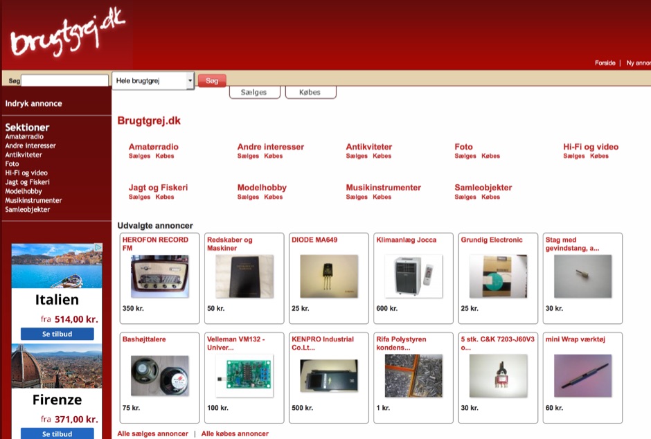 Brugtgrej presents a Danish online classifieds platform specifically for amateur radio operators and electronics enthusiasts. The platform facilitates the buying and selling of used equipment, including transceivers like the Icom IC-7410, various components such as X'TAL FILTER FMT-15A and TRANSISTOR 2SC3019, and accessories like Sadelta microphone capsules and SMA to SMA extenders. Users can post free advertisements for items they wish to sell or acquire, covering categories beyond amateur radio, including antique radios, military radios, and radio tubes. The site lists active advertisements, with 3136 online ads and 167 online users at the time of analysis, indicating a dynamic marketplace. It also features a forum for community interaction, discussing topics like repeater rings on 1297 MHz and FT8 activity. The platform's structure supports both 'Sælges' (for sale) and 'Købes' (wanted) listings across its various sections. Specific items observed include a Miniwatt pentode 4689, various capacitors and coils, and general electronic components, demonstrating the breadth of offerings available to the amateur radio community.
 -
 Sixty-meter repeaters typically use a 1 MHz frequency separation between input and output, while 2-meter repeaters commonly employ a **600 kHz** split and 70-centimeter repeaters use a **5 MHz** offset. This article details the fundamental technical principles of amateur voice repeaters, explaining how they extend VHF/UHF communication range by receiving on one frequency and simultaneously retransmitting on another. It covers essential components such as receivers, transmitters, filters, and antennas, often situated on elevated locations for optimal coverage. The resource delves into the critical challenge of _desensing_—where the repeater's strong transmit signal overpowers its own receiver—and the engineering solutions employed, including antenna separation and the use of high-Q cavity filters. It also explores various control and timing systems, from basic squelch activation to more sophisticated microcontroller-based boards that manage functions like voice identification, time-out timers, and fault protection. Different access methods are discussed, including open access, toneburst, CTCSS subtone, and DTMF, each offering distinct advantages for managing repeater usage and mitigating interference. Furthermore, the article examines repeater linking, both conventional RF methods and modern internet-based solutions, highlighting how linking expands coverage and promotes activity across multiple repeaters or bands. It introduces less common repeater types such as 'parrot' repeaters, which use a single frequency and digital voice recording, and linear translators, capable of relaying multiple signals and modes simultaneously across different bands, often found in amateur satellites.
 -
 Operating in the **microwave** spectrum, Response Microwave, Inc. specializes in the design and manufacturing of RF and microwave signal processing components and subsystems. The company's product line encompasses a wide array of offerings, including Connectivity Series components, rotary joints, phase shifters, cable assemblies, surge protectors, terminations, Hybridline/Couperline products, circulators/isolators, directional couplers, quadrature hybrids, attenuators, custom assemblies, filters/diplexers, DC blocks & bias tees, power dividers/combiners, laser diodes & drivers, high-frequency connectors, and precision test accessories. This extensive catalog supports various applications requiring precise signal manipulation and transmission at elevated frequencies. The resource provides access to a comprehensive product catalog and a dedicated connector catalog, detailing specifications for components like **high-frequency connectors** and test cables. While specific performance data or comparative analyses are not directly presented on the main page, the breadth of products indicates a focus on providing foundational building blocks for microwave systems. The company emphasizes customer service and aims to be a reliable source for RF/Microwave/Optics product requirements, serving a growing customer base with its specialized component offerings.
 -
 Microprocessor based interface designed receives a signal from a Morse key, processes it, and re-transmits it to the radio. A microprocessor in the circuit is pre-programmed with a proprietary algorithm which makes a number of measurements and adjustments to the less percise human generated code.
 -
 A microprocessor based interface designed to go between a standard Morse code key and a radio transmitter. The circuit receives a signal from the key, processes it, and re-transmits it to the radio.
 -
 The San Bernardino Microwave Society, operating under the callsign _W6IFE_, serves as a significant technical hub for amateur radio operators specializing in frequencies above 1 GHz. This organization's influence extends across Southern California, providing a centralized resource for advanced RF experimentation and **regional frequency management** within the microwave spectrum. Its permanent value lies in its extensive archive of technical papers and project documentation, which are critical for operators engaged in high-frequency design and deployment. The society's infrastructure is primarily intellectual, focusing on the dissemination of specialized knowledge rather than a conventional repeater network. It offers a robust collection of technical papers from prominent members like K6PIP, K6BLG, and WA6EXV, covering topics such as Rubidium oscillator data, logging software, and filter design. This resource facilitates advanced amateur radio operations, including participation in microwave contests and the development of custom transverters for bands like 24 GHz. The site also details various member projects, such as the Owens Valley Radio Observatory Project, showcasing practical applications of **RF propagation analysis** and system integration. DXZone Focus: Microwave | Technical Papers | RF Propagation | Contest Results
 -
 Thsi article describes a microcontroller driven semi-automatic antenna tuner capable of handling power levels up to 150 watts. The device is a low pass filter tuner manually tuned by setting the optimized L/C combination by hand and then storing the values into the EEPROM of the mictrocontroller to recall them later (seperately for each band from 80 to 10 meters including WARC bands)
 -
 Microwaves101 provides an extensive repository of information covering fundamental principles of microwave design, targeting engineers and radio amateurs interested in the higher frequency spectrum. The site features a detailed _encyclopedia_ of microwave terms and concepts, alongside practical design considerations for various components and systems. It serves as a foundational reference for understanding RF propagation, transmission lines, and active/passive microwave circuits. The resource includes numerous calculators for impedance matching, filter design, and other critical RF parameters, facilitating hands-on project development. Discussions on **10 GHz** equipment and **24 GHz** projects highlight practical amateur radio applications, extending to operations up to 134 GHz. Content spans from basic theory to advanced topics like MMIC design and antenna characteristics, supporting both educational and practical endeavors in microwave technology.
 -
 Microwave Filter Company is a leader in the design, development and manufacture of high quality passive electronic filter products in the 5 Hz to 50 GHz frequency spectrum.
 -
 Direct conversion receivers (DCR) are gaining renewed interest due to advancements in semiconductor technologies and their suitability for integration in compact, low-cost, multi-standard applications. Unlike traditional superheterodyne receivers, DCR eliminates image frequencies and bulky off-chip filters but introduces challenges like DC offsets, nonlinearity, and noise issues. This tutorial explores DCR's historical development, compares it with other receiver architectures, and addresses its inherent obstacles. DCR's potential for integration and compatibility with software-defined radio highlights its role in modern communication systems despite its technical complexities.
 -
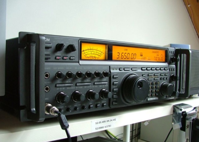 Inrad Roofing Filter installation instruction, The IC-775 Roofing Filter Mod consists of a 6 pole, 5 kHz wide filter followed by a high dynamic range, feedback amplifier.
 -
 An **Arduino LC Meter** provides an accessible solution for precisely measuring inductance and capacitance values, crucial for RF circuit design, filter tuning, and troubleshooting in amateur radio applications. This project details the construction of a low-cost, accurate instrument using readily available components, making it an attractive alternative to commercial units for hams and electronics enthusiasts. The build process involves assembling a resonant circuit, integrating an Arduino microcontroller for frequency measurement, and displaying results on an LCD. Key components include an Arduino Uno, a 16x2 LCD, a 74HC14 Schmitt trigger inverter, and a few passive components. The design leverages the Arduino's processing power to calculate L and C values from resonant frequency shifts. Calibration procedures are outlined to ensure measurement accuracy, which is vital for critical RF work. The project includes schematics, a parts list, and the necessary Arduino code, enabling hams to construct a functional LC meter for their workbench.