Search results
Query: over voltage
Links: 30 | Categories: 0
-
 Demonstrates the construction of **magnetic loop antennas**, detailing both multi-turn and single-turn designs. It covers a 30-inch diameter multi-turn loop for 80 meters, based on a February 1996 QST article, and an octagon single-turn loop made from 15mm copper tube with a 4.8-meter circumference, operating from 7 MHz to 14 MHz. The document also presents a smaller 800mm diameter loop for 14 MHz to 28 MHz, emphasizing the importance of high-voltage tuning capacitors. Covers the design and construction of custom **butterfly capacitors** and piston capacitors, including a split stator capacitor with 140 pF capacitance and a 6000 Volt rating, and a butterfly capacitor with 5-65 pF and 7200 Volt rating. It explains why butterfly capacitors are preferred over split stator types for high power applications due to lower losses and direct series connection of rotors, reducing resistive losses from wiper contacts. Material recommendations include clear PVC for plates and brass or stainless steel for non-magnetic hardware. Addresses practical considerations such as feeding the loop with a shielded 1/5 Faraday loop made from RG213 or RG8 coax, achieving VSWR 1.1 across bands, and optimizing its placement 180° from the capacitor. It also discusses mechanical joint resistance, dissimilar metal oxidation prevention using Vaseline, and a simple method for determining radiation angle with a TL-light tube. The guide includes diagrams for rotor, stator, and end plate construction.
 -
 For radio amateurs considering homebrew antenna projects, this resource details several designs from WE6W, an experienced operator. It covers the construction and characteristics of a _160 Meter QRP Loop Antenna_ optimized for high voltage, along with standard and folded variations of the double bazooka antenna. The site also presents a unique Field Day antenna design and instructions for building a Sterba Curtain, a directional array known for its gain. Each design includes practical insights from the author's building experience. The author provides comparative data, such as the performance of a standard bazooka against a traditional dipole, offering real-world context for antenna selection. The Sterba Curtain section includes notes on its beamwidth and gain, crucial parameters for directional operation. These designs are suitable for hams looking to experiment with cost-effective, high-performance antennas for various bands and operating scenarios, from QRP on 160m to directional DXing with a Sterba Curtain, which can offer significant forward gain, often exceeding **10 dB**.
 -
 Which balun to use? The hybrid balun promises advantages over both voltage and current baluns by ZS1AN
 -
 Unified Microsystems presents a range of amateur radio products, notably the **XT-4 MK2 CW Memory Keyer**, a battery-powered iambic keyer designed for portable operations like Field Day, POTA, SOTA, and DXpeditions. It features four non-volatile memories, each storing approximately 240 Morse characters, and operates at speeds from 8-45 WPM. The XT-4 MK2 also includes an auto power save function and paddle reverse, making it adaptable for multi-operator setups. Beyond the XT-4 MK2, the site details the **W9XT Contest Card**, a PC plug-in board offering DVK and CW interface capabilities, allowing operators to record and playback CQs and contest exchanges. Other offerings include the BevFlex-4X RX Antenna System, RAS-4 RX Antenna Switch, VK-64 Voice CW Keyer, and various USB interfaces. Additional products cover electronic development, such as the ATS-1 Terminal Shield for Arduino™ and VR-X Power Supply Voltage Regulators, demonstrating a broader scope beyond just operating accessories. The XT-4Beacon MK2 / CW IDer is also highlighted for beacon projects, capable of storing messages up to 5 minutes at 25 WPM.
 -
 Presents the design and construction of the OK2FJ Bigatas, a portable, automatically tuned vertical antenna covering 80 through 10 meters. It details two distinct control systems: one utilizing BCD band data from Yaesu FT-857/897 transceivers, and another employing voltage level sensing for the Yaesu FT-817. The resource provides specific instructions for building the antenna's radiating element, loading coil with switchable taps, and the control circuitry, emphasizing the use of readily available components. The article outlines the physical construction of the antenna, including the use of duralumin tubes for the radiator and a PVC tube for the coil form. It specifies coil winding details, tap points, and the integration of radial wires for ground plane operation. The control electronics section provides schematics and component lists for both the BCD decoder (using a 74LS42 IC) and the voltage comparator (using an _LM3914_ bargraph driver), enabling rapid, automatic band switching without the minute-long tuning delays common in other systems. Crucially, the antenna achieves rapid band changes, with typical SWR values centered on common operating segments, such as **3.7 MHz** for 80m SSB. It also discusses modifications for CW operation on 80m and the trade-offs between antenna efficiency and full-range automatic tuning on higher HF bands, where manual adjustment of radiator length is suggested for optimal performance on 15m, 12m, and 10m. The resource includes construction photos and a discussion of cable requirements for reliable operation.
 -
 Need a variable power supply that is short circuit protected and over voltage protected; Here is a good one that can be built cheap by VE3IVJ
 -
 Overvoltage protection, Voltage stabilization, Grounding in wiring, Ground wire resistance
 -
 The document provides a comprehensive overview of baluns, which are devices used to connect balanced loads, like dipole antennas, to unbalanced inputs, such as coaxial cables. It covers various types of baluns, including voltage and current baluns, and their design, construction, and testing. The text discusses the importance of baluns in preventing RF currents on coax shields and their applications in Ham radio setups. It also includes practical advice on selecting and using baluns based on antenna impedance and power ratings, along with detailed performance evaluations and construction tips for different balun configurations.
 -
 A 4 AMP / 18V regulated power supply schematic, designed by _ON6MU_, provides a detailed circuit diagram for constructing a robust power source. The design focuses on delivering a stable 18-volt output at up to 4 amperes, crucial for powering various amateur radio equipment. This resource presents a clear visual representation of component interconnections, including rectifiers, filter capacitors, and voltage regulation stages, essential for DIY enthusiasts building their shack infrastructure. The schematic's clarity facilitates understanding the power flow and component roles within the circuit. This circuit design offers a practical solution for hams needing a reliable 18V supply, potentially useful for driving specific transceivers, amplifiers, or accessory circuits. While specific performance measurements or comparisons to other designs are not detailed, the schematic itself serves as a foundational blueprint. Builders can adapt or modify the _power supply_ to suit their particular needs, such as integrating overcurrent protection or fine-tuning the output voltage with adjustable regulators. The straightforward presentation makes it accessible for those with basic electronics knowledge to assemble and troubleshoot.
 -
 Presents a QRP AM/CW transmitter project specifically designed for the 10-meter band, utilizing a crystal oscillator and a collector-modulated AM oscillator. The design employs a 2N2219(A) transistor in a Colpitts configuration, generating 100 to 350 mW of RF output power depending on the 9-18 Volt supply voltage and modulation depth. Frequency stability is maintained by a 28 MHz crystal, with fine-tuning possible via a Ct1 trimmer capacitor for approximately 1 kHz adjustment. The resource details the RF oscillator stage, implemented with a 2N2219 NPN transistor, emphasizing frequency stability and low power dissipation. It also covers the amplitude modulation stage, managed by a 2N2905 PNP transistor, which impresses audio information onto the carrier. Selective components (C3, C4, C7, C5) enhance voice frequencies within a +/- 5 kHz bandwidth, and modulation depth is controlled by R2 and R3. The project includes a 3-element L-type narrow bandpass filter (Ct3, L3, C10) to suppress harmonics and ensure a clean output signal. The project provides a complete schematic diagram, a comprehensive parts list including specific capacitor, resistor, and inductor values, and construction notes for the coils (L1, L2, L3). It also offers practical advice on enclosure requirements, suggesting an all-metal case or a PVC box with graphite paint for RF shielding. Operational parameters such as current draw (27mA@9V to 45mA@16V) and input impedance (50 Ohms) are specified, alongside guidance on antenna matching and the importance of a valid amateur radio license for 10-meter band operation.
 -
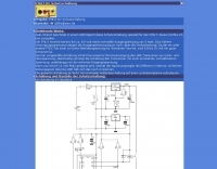 A schematic for a DX circuit protection for the Yaesu FT-817, provides protection from the external power supply overvoltage by DL2LTO in german
 -
 Protecting amateur radio equipment from transient overvoltages requires robust lightning and surge protection, which is the focus of Electronic Specialty Products. The company provides various devices, including coaxial lightning arrestors for antenna feedlines and surge protectors for AC power lines and data circuits. These devices are engineered to divert high-energy surges, such as those caused by direct or indirect lightning strikes, away from sensitive transceivers, amplifiers, and computer components, thereby preventing catastrophic damage. Key products include the _Coaxial Lightning Protector_ series, designed for various impedance levels and frequency ranges up to 3 GHz, and the _AC Line Surge Protector_ for shack power distribution. Effective deployment of these protection devices can significantly reduce the risk of equipment failure and ensure operational continuity during severe weather. For instance, a properly installed coaxial arrestor can handle peak currents of **20 kA**, while AC line protectors offer clamping voltages typically below 400V. Comparing different models reveals varying levels of insertion loss and return loss, with some coaxial units exhibiting less than 0.1 dB loss at 500 MHz, making them suitable for high-performance HF and VHF/UHF operations. Integrating these components into a comprehensive grounding system is crucial for achieving maximum protection against both common-mode and differential-mode surges.
 -
 Operating a ham station often involves encountering radio frequency interference (RFI), RF feedback, or RF burns, which are frequently misattributed to poor equipment grounding. This resource meticulously dissects these assumptions, asserting that RF grounds on the operating desk often merely mask more significant system flaws. It identifies five primary causes for RF problems, including antenna system design flaws, proximity of the antenna to the operating position, DC power supply ground loops, equipment design defects, and poorly installed connectors or defective cables. The content emphasizes that issues like "hot cabinets" or changes in SWR when connecting a ground indicate substantial RF flowing over wiring or cabinets, a phenomenon known as common-mode current. The article provides detailed explanations of common-mode current generation, particularly from single-wire fed antennas like longwires, random wires, and OCF dipoles, which inherently present high levels of RF in the shack. It also illustrates how vertical antennas, lacking a perfect ground system, can excite feed lines with significant common-mode current. Through simulations, the author demonstrates how a dipole without a proper _balun_ can cause RF problems at the operating desk, showing current patterns and voltage distributions on feed line shields. The discussion extends to the proper application of _RF isolators_ and _ferrite beads_, clarifying their role in modifying common-mode impedance on cable shields and cautioning against their use as a band-aid for fundamental system defects. The resource advocates for correcting the actual source of RF problems, such as antenna system issues or poor connector mounting, rather than relying on internal shack grounding or isolators. It highlights that properly functioning two-conductor feed lines, like coaxial or open-wire lines, should result in minimal RF levels at the operating position, even without a desk RF ground. The author shares personal experience, noting that his stations since the late 1970s have operated without RF grounds at the desks, relying instead on proper antenna system design and feed line integrity.
 -
 Vapex Tech offers over **150 different battery products** tailored for diverse applications, including specific models for Icom, Kenwood, and Yaesu handheld transceivers. The product catalog details specifications for NiMH, LiPo, and LiFePO4 chemistries, providing crucial data on voltage, capacity, and discharge rates. Customers can browse by application, such as _Airsoft Batteries_ or _Model Control Batteries_, or directly by consumer battery types like AA and AAA cells. The resource presents a structured e-commerce platform where users can filter products by category, view detailed item descriptions, and proceed with online purchases. Each product listing includes high-resolution images and key technical parameters, enabling informed selection for specific radio equipment. Operational hours are clearly stated as 9am-5pm Mon-Fri and 9am-12pm Sat, with contact information including a sales email and phone number for direct inquiries. The site also features a "Latest News" section, indicating ongoing updates regarding product availability or company information.
 -
 T2FD is a 600-900 ohms folded dipole, terminated with resistor. Feed impedance is coupled with 50/600 ohms voltage balun. It is a wide band antenna with rather low SWR over the full designed frequency range: antenna tuner is seldom needed.
 -
 A synthesized 2.3 GHz Amateur Television (ATV) transmitter design, conceived by Ian G6TVJ, is presented, targeting broadcast-quality video performance on the 13cm band and extending up to 2.6 GHz. The core of the design utilizes a commercial Z-comm Voltage Controlled Oscillator (VCO) that tunes from 2.2-2.7 GHz, providing a +10 dBm output and simplifying RF alignment. This VCO's stability, originally intended for narrowband applications, readily accepts high-frequency video modulation, contributing to the transmitter's robust performance. The exciter stage, incorporating a Mini Circuits VNA 25 MMIC amplifier, boosts the signal to +16dBm, while a Plessey SP4982 prescaler divides the output frequency for the synthesizer. The synthesizer employs a Motorola MC145151 CMOS parallel IC, favored over the common Plessey SP5060 for its superior video modulation characteristics and ease of programming without microprocessors. This choice addresses issues like LF tilt and distorted field syncs often seen with SP5060 designs, particularly when operating through repeaters or over long distances. The MC145151 divides the signal further, enabling precise frequency stepping, with programming handled by EPROMs for channel selection and LED display. The loop filter network, critical for video integrity, was developed through experimentation to prevent the PLL from reacting to video modulation, ensuring a clean transmitted picture. The transmitter incorporates a Down East Microwave commercial power amplifier module, delivering approximately 1.6W output, driven by the exciter through a 3dB attenuator. Construction involves surface-mount SHF components on micro-strip lines etched onto double-sided fiberglass board, housed within a tinplate box. The design boasts no AC coupling in the video path, preserving low-frequency response, a common failing in other ATV transmitters. Performance tests with a 50Hz square wave revealed no LF distortion, and a calibrated "Pulse & Bar" signal showed a near 100% HF response, demonstrating its capability for high-quality ATV transmissions.
 -
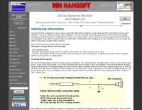 Demonstrates the fundamental principles for connecting a personal computer to a ham radio transceiver, specifically for utilizing sound card-based digital mode software like those in the MM Hamsoft suite. It details the basic hardware setup, emphasizing the use of shielded leads and proper audio routing from the radio's output to the sound card's input, and from the sound card's output to the radio's microphone or data input. The resource highlights the critical need for transmit attenuation, suggesting a 100:1 voltage divider to prevent overdriving the transmitter's audio stage, and mentions the optional addition of ferrite beads and decoupling capacitors for RFI mitigation. The guide also points to external resources for more detailed pin-outs and interface schematics, such as a specific QSL.net page, and recommends consulting the help files within MM Hamsoft programs for interfacing specifics. It underscores that while the process is straightforward, understanding the audio level management and proper cabling is key to successful operation. The author, VE5KC, provides practical advice drawn from common issues encountered by operators setting up digital mode stations.
 -
 Demonstrates the construction of a high-power 6-meter (50 MHz) amplifier, specifically designed for demanding modes like EME, TEP, and multiskip Es. It details the use of a _GU-43B_ tetrode in a grounded-cathode configuration, emphasizing the need for stabilized grid voltage and input capacitance compensation. The resource provides a comprehensive schematic, power supply design, and practical considerations for component sourcing, particularly for high-voltage and high-current sections. The builder achieved an output power of **1250 watts** with an anode current of 0.65 amperes and 3200 volts anode voltage. The article also covers the physical construction within a modified P6-31 enclosure, outlining the internal layout for RF and power supply sections, and includes photos of the completed unit. It highlights critical safety precautions for working with high voltages and reactive currents up to **20 Amperes** in the P-network.
 -
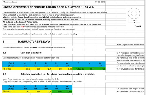 This EXCEL Program Worksheet calculates the safe operating conditons for a toroidal transformer operating between 1 and 50 MHz. Manufacturer data for complex permeability, magnetic dimensions, and saturation flux density must be available. Some core types which are commonly used in amateur transmission are included. The program produces limiting winding voltages for linear operation and temperature rise over the range of frequencies and power specified.
 -
 Offers a range of high-performance RF interconnect solutions, addressing the critical need for reliable signal integrity across diverse radio frequency applications. Their product line includes custom cable assemblies, various **RF connectors** (such as SMA), adapters, and terminators, designed to meet stringent specifications from DC up to 40 GHz. These components are essential for maintaining low insertion loss and excellent VSWR in demanding environments, from test benches to operational communication systems. The company specializes in providing tailored solutions for both commercial and government sectors, emphasizing precision manufacturing in Warner Robins, Georgia. Their offerings are crucial for engineers and operators requiring specific lengths, connector types, and performance characteristics for their radio equipment and test setups. Ensuring robust connections and protection against transient voltage events, their **surge protectors** are integrated into systems to safeguard sensitive electronics from damage, a common concern in outdoor or high-power installations.
 -
 Operating in a Single Operator Two Radios (SO2R) setup, especially with beverage antennas, often exposes the receiving radio's front-end to significant RF energy from the transmitting radio. This resource details a practical, homebrew receiver protection circuit designed to mitigate this risk. The core of the design involves a non-inductive 2W 22 Ohm carbon composition resistor in series with the RX antenna line, followed by two stacks of four fast-switching diodes (e.g., _1N914_) configured in opposite polarizations. This arrangement effectively clamps the incoming voltage to approximately 2.8 V peak-to-peak, safeguarding sensitive receiver input components. The series resistor plays a crucial role by absorbing excess power, preventing the diodes from exceeding their current ratings and potentially failing open, which would leave the receiver unprotected. The author, _N4KG_, measured up to 50 watts of coupled power between 80M slopers on the same tower, highlighting the necessity of such protection. The design is presented as a cost-effective solution to prevent damage to receiver input transformers, with the author noting successful protection of a receiver even after a resistor showed signs of overheating. This simple circuit can be integrated via a transverter plug, offering a robust defense against high RF input.
 -
 Enables Android users to operate various _miniVNA_ antenna analyzers via Bluetooth, USB, or Wi-Fi, providing a portable solution for RF measurements. The application supports full control over data acquisition, offering features like custom frequency range selection from 1 KHz to the VNA's full range, and automatic screen adaptation for diverse Android device resolutions. It facilitates intuitive, wizard-based calibration for both reflection and transmission modes, saving calibration data for different VNA types (Standard, Pro, Pro with Extender) to avoid repeated procedures. The software displays critical parameters such as SWR, |Z|, Return Loss, Phase, Rs, and |Xs| on 2-axis graphs or Smith charts, with multi-touch gestures for zoom and frequency shift. It includes a frequency generator mode with independent channels and attenuator control for the miniVNA Pro, along with a sweeper function. The cable data mode automatically calculates phase and loss, measures cable length from less than 1 meter to hundreds of meters, and includes a table of common coax cable velocity factors. An experimental X-tal mode measures resonance frequency, Rs, and Q. Data export options include CSV, ZPLOT, and S1P formats, with CSV import capability. The application also features an SM6ENG Audio mode for SWR tuning without visual reference and provides a miniVNA battery voltage indicator. It supports a wide frequency range, with the miniVNA Extender extending coverage up to **1500 MHz**. The application is compatible with Android version 2.2 and later, tested on devices like the _Galaxy TAB 7.7 P6800_.
 -
 This tutorial provides detailed instructions for constructing a DIY magnetic loop antenna, ideal for amateur radio operators seeking efficient short wave communication. The design features a remote tuning system utilizing an Arduino and RC servo, making it suitable for indoor use where larger antennas cannot be installed. Magnetic loop antennas are compact and can operate effectively in confined spaces, but they do require careful handling due to the high voltages and currents they generate during operation. Users should possess the necessary technical skills to implement this project safely. The tutorial includes a comprehensive overview of the antenna's theory, specifications, and mechanical design. It outlines the components needed, including a Soviet-made variable capacitor and a digital RC servo for tuning. Safety precautions are emphasized, as the antenna can produce several kilovolts of voltage and high currents. The project is not certified for safety, and users are advised to proceed at their own risk. The tutorial also provides diagrams and explanations of the antenna's operation, making it a valuable resource for both beginners and experienced operators looking to enhance their setup.
 -
 his article explores the construction of a PL519 tube amplifier, utilizing Ulrich L. Rohde N1UL's insights. Focusing on a modest 25W continuous output, the design ensures robustness with forced air cooling. The detailed breakdown covers input matching, screen grid voltage generation, bias adjustment, anode power supply, heater power supply, and monitoring circuitry, providing valuable guidance for ham radio enthusiasts.
 -
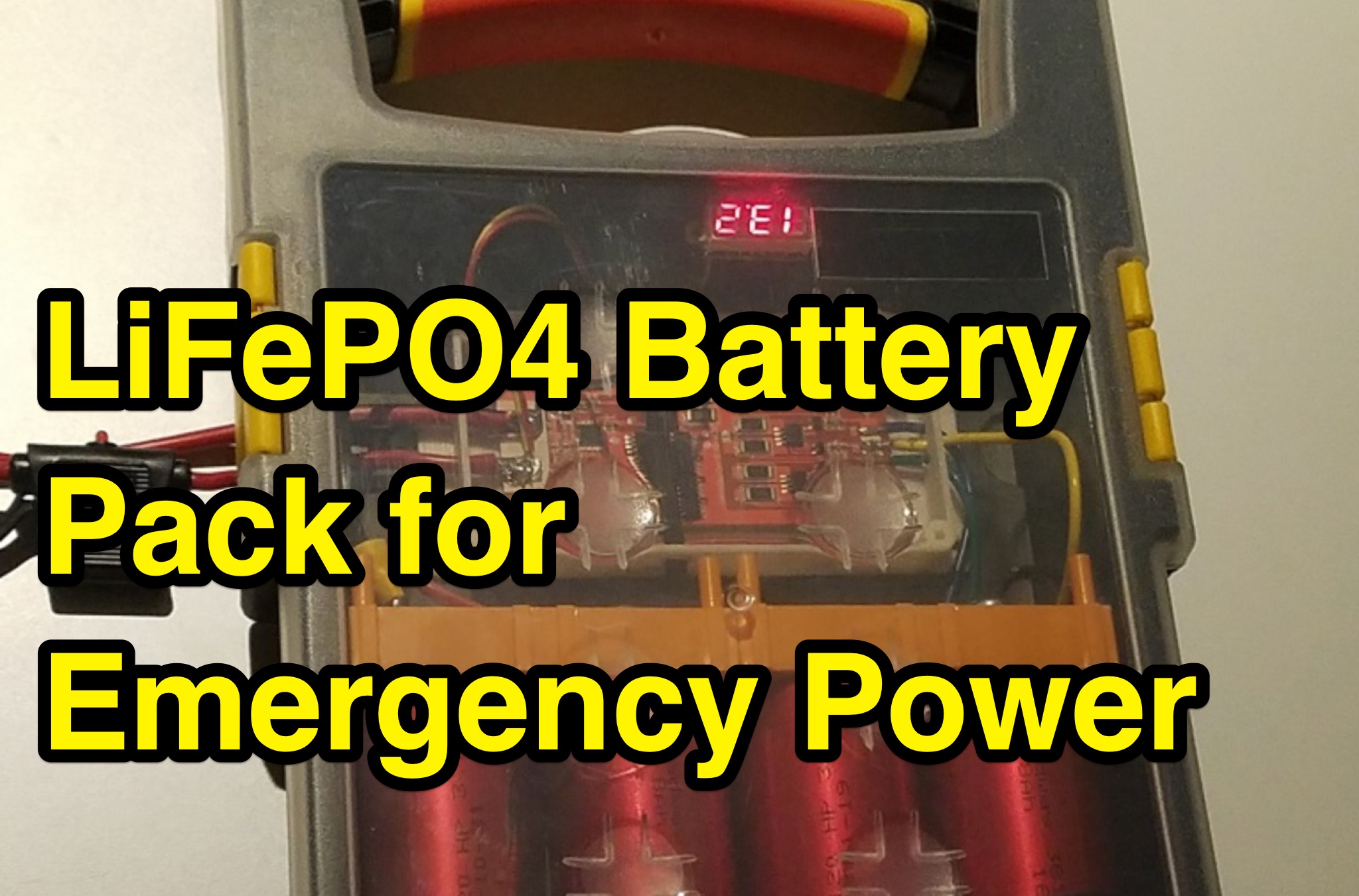 Four _Headway 38120_ LiFePO4 cells form the core of an 8AH 12V battery pack, designed for reliable emergency and field power in amateur radio operations. These batteries offer significant advantages over traditional lead-acid types, including a lifespan up to **10x** longer in charge/discharge cycles, lower internal resistance for faster recharging, and a flatter discharge curve that maintains voltage stability during use. Their inherent safety, being a flame-retardant technology, makes them a preferred choice for portable applications. Proper configuration, including parallel/serial setups, and careful charging/discharging protocols are crucial for maximizing battery life. Each cell has a nominal voltage of 3.2 volts, with a maximum charge voltage of 3.65 volts. A Battery Management System (BMS) is highly recommended to prevent overcharging or deep discharging, safeguarding the cells. The project emphasizes safety, noting the batteries' high short-circuit capacity of **200 AMPS** and the critical importance of incorporating an inline fuse between the battery pack and the load. Components like the battery holder, buss bars, and a suitable case are also detailed.
 -
 Detecting stray RF voltages on station grounds, chassis, and interconnecting cables is crucial for preventing program and hardware failures in the shack. This article details the construction and application of an LED RF V-probe, which offers significantly higher sensitivity compared to conventional neon lamp indicators. The probe leverages two specific properties of modern red LEDs: their ability to glow at microampere currents and their rectification capability at frequencies up to tens of megahertz. The design features a simple circuit with two LEDs, allowing for indication of both positive and negative RF voltage half-waves. The minimum detectable RF voltage is approximately 2 V, a substantial improvement over the 40-60 V threshold of neon bulbs. The resource illustrates the probe's physical construction on a PCB and provides a direct comparison demonstrating its superior sensitivity in detecting RF fields near a coil. Two operational modes are described: a non-contact mode for high RF voltages (above 15-20 V) and a direct-contact mode for measuring lower RF voltages, with a safety caution for the latter. Practical examples show the probe's use in analyzing RF voltage distribution across a radio station setup at 1.84 MHz and 24.9 MHz, revealing insights into common-mode current issues and the effectiveness of mitigation strategies like adding radials.
 -
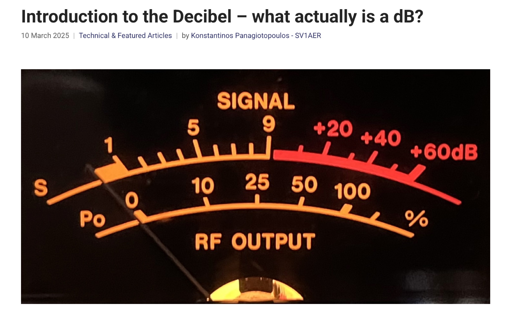 This article provides a comprehensive introduction to the decibel (dB), its logarithmic nature, and its applications in power, voltage, and antenna gain calculations. It explains how dB simplifies comparisons in electronics, telecommunications, and audio perception. The author clarifies key mathematical concepts, including power ratios, voltage doubling, and absolute levels like dBm and dBV. The discussion on S-units and antenna system gain is particularly relevant for radio amateurs. Overall, this is an informative and well-structured guide to understanding and applying decibels in technical fields.
 -
 After years of reliable performance, a 26-year-old Icom 706MK2G exhibited an unusual deviation during FM transmission, with the actual frequency being 10kHz off from the displayed frequency. Additionally, the power meter showed a sharp dip during transmission. Upon investigation, it was discovered that the FM VCO voltage adjust variable had become dirty and sluggish over time. By adjusting the variable capacitor and cleaning it with switch cleaner, the issue was resolved, restoring stable power output and accurate frequency transmission.
 -
 The **Yaesu FRG-100** shortwave receiver, introduced in 1992, operates across a frequency range of 50 kHz to 30 MHz, accommodating AM, LSB, USB, and CW modes, with an optional narrow-band FM capability. Its physical dimensions are 238 x 93 x 243 mm, with a weight of 3 kg, making it suitable for both portable and fixed station deployments. Power options include standard mains voltage or 12VDC, providing operational flexibility for diverse listening environments. The front panel integrates a manual tuning knob, an analogue signal strength meter, and an LCD display that provides critical information such as frequency, operating mode, memory channel, and time. Users can configure various operational parameters, including tuning steps and bandwidth filters, to optimize reception for specific signals. This review highlights the FRG-100's straightforward interface and its utility for shortwave listening enthusiasts. The design emphasizes user-friendly adjustments for settings, which contributes to its appeal among those interested in general coverage reception.
 -
 This online construction guide details the assembly of a signal generator specifically for the **13cm band** (2.4 GHz). The curriculum focuses on the integration of a Voltage Controlled Oscillator (VCO), specifically the ROS-2400, to produce a stable RF signal. The resource outlines the necessary components for frequency generation and output, including the use of a Mini-Circuits MMIC amplifier for signal conditioning. The construction protocol involves configuring the ROS-2400 VCO to operate within the 2.3 GHz to 2.45 GHz range, ensuring frequency coverage for amateur radio _microwave experimentation_. The guide specifies the output power level, approximately 70mW, directly from the MMIC stage, indicating its application as a low-power instrumentation source rather than a transmit-capable device. This project provides a practical example of constructing a dedicated test instrument for microwave frequency measurements and system alignment on the **13cm band**. DXZone Focus: Construction Guide | 13cm Signal Generator | VCO Integration | Microwave Experimentation