Search results
Query: react
Links: 27 | Categories: 0
-
 Presents the KE4UYP linear-loaded vertical antenna design, which introduces very little loss on 80 or 160 meters, achieving an overall radiation efficiency of 80% to 85%. This design addresses common pitfalls of traditional base-fed verticals by placing the majority of the current at the top of the antenna, eliminating the heavy reliance on extensive ground radial systems. The author's initial 10-meter model, only three feet tall, yielded 5/9 signal reports to Anchorage, AK, and Europe, confirming its effectiveness. The antenna incorporates both vertically and horizontally polarized radiators, with a 1/4 wavelength horizontal counterpoise located at the feed-point, near the top, to create an almost totally omnidirectional pattern with high wave angle horizontally polarized radiation. This dual polarization ensures even illumination across all take-off angles, making it effective for both local contacts and **DXing**. The vertical element is linear loaded, adding capacitance reactance and making it longer than the horizontal element to achieve resonance and raise the feed-point impedance to 50 ohms. Fine-tuning the antenna requires careful adjustment, as tower reactance can vary. The article suggests starting with 80 feet for 80m and 170 feet for 160m for the vertical wire, then trimming for resonance. Bandwidth specifications include 300 kHz under 2:1 **SWR** on 80m and 100 kHz on 160m when suspended between trees, or 150 kHz on 80m when side-mounted on a tower.
 -
 This improved multiband trap dipole introduces a new trap design and a change in trap location. The antenna features double-coaxial-cable-wound traps having lower reactance and a higher quality factor (Q) than earlier coax-cable traps by W8NX
 -
 Excel spreasheet that calculate virtually every transmission line parameter that one may need. Include Length conversions, Reactance and Length of Stubs
 -
 ICANN policies require registrars to verify domain registrant email addresses within 15 days of registration or transfer, a critical step for maintaining domain activity. Failure to complete this verification process results in the suspension of the domain, rendering the associated website inaccessible. This resource details the common reasons for such suspensions, including new registrations, changes to registrant email addresses, or domain transfers where verification was not completed. To reactivate a suspended domain, the registrant must click a verification link sent to their email address by the registrar. The process typically resolves the suspension within 30 minutes after successful verification. Registrants can request a resend of the verification email through their domain provider or use a trigger code if available. This ensures compliance with ICANN's _Registrant Verification Policy_ and restores website functionality.
 -
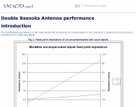 The Double Bazooka Dipole is a half wave dipole with an attempt at compensation of the reactance change that occurs around resonance for a half wave dipole.
 -
 An antenna system is more easily interfaced to a radio when the input reactance at the feedline terminals is low or close to series resonance
 -
 LCF online Calculator, calculate relation between Frequency Capacitance Inductance and Reactance
 -
 HAMIC, is a program designed to simplify a number of calculations commonly used by HAMs. It is designed for the HAM radio hobbyist, but may be useful to others as well. HAMIC has a simple to use, but powerful graphical interface that allows solving simple circuits such as resistors in series or parallel, or more complex circuits such as L networks or T networks. As well, other calculations such as SWR and reactance conversions are supported. Windows shareware.
 -
 Accurately determining an antenna's feedpoint impedance is crucial for optimal performance, especially when experimenting with new designs or making adjustments. While SWR meters provide basic information, a full complex impedance measurement reveals the resistive and reactive components, which are essential for proper matching. Modern antenna analyzers, like the _Palstar ZM30_ or MFJ259B, simplify this task, but measurements taken through a transmission line require careful interpretation due to impedance transformation. This resource details a calibration method to precisely account for the effects of the feedline. It explains how a transmission line can significantly alter the measured impedance, illustrating this phenomenon with a Smith Chart example where an 80m antenna's [22 + j6] Ohms feedpoint impedance transforms to [82 + j45] Ohms after a 10m line. The guide demonstrates using a transmission line calculator applet, such as the one by W9CF, to reverse this transformation. It outlines the process of calibrating a specific length of RG174 coax, showing how an initial 26ft estimate was refined to **25.85ft** to accurately predict a known 22 Ohm load, significantly improving accuracy over uncalibrated results.
 -
 A method for supporting a balun on a Chushcraft A3S antenna. This allows the balun to be isolated from the boom, thus reducing the effect of introduction of reaction with the balun core.
 -
 Windows program for analyzing vertical antennas. This program shows the resistance and reactance to be expected looking into a cylindrical metallic tower over a perfect ground. It gives a useful approximation of the values to be expected in a real-world situation.
 -
 A 50-ohm generator feeding a 50-ohm line connected to a _quarter-wave transformer_ (150 ohms) terminated in a 450-ohm load is analyzed to understand transient behavior. The paper meticulously tracks voltage and current waves, reflection coefficients, and power levels through a sequence of events, starting from quiescent conditions. It details how incident and reflected waves combine and interact at impedance discontinuities, illustrating the dynamic changes in impedance and SWR at various points in the system. The analysis reveals that the impedance at the interface between the 50-ohm line and the 150-ohm transformer changes from 150 ohms to **64.3 ohms** after the first reflected wave arrives. Subsequent reflections cause the impedance to asymptotically approach 50 ohms, reaching **53.22 ohms** after five wave terms. The study also examines the generator's reaction to transient SWR changes, noting that a 3:1 SWR can temporarily reduce generator output to 0.75 watts, but these effects are temporary and diminish as the system approaches steady-state conditions.
 -
 CREST Communications REACT Team #4252 has been an active member of the community for almost 30 years and is one of the largest REACT Teams in the United States.
 -
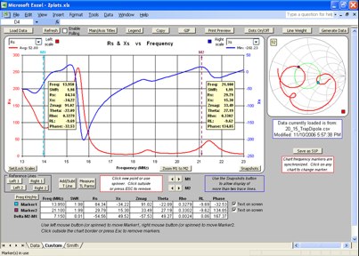 MS Excel document that allows you to plot SWR, resistance, reactance, impedance magnitude and angle and more from a variety of sources
 -
 When I tell friends that I enjoy amateur radio contesting, their reaction is usually a quizzical stare. "What's that?" It is hard to explain in the span of a cocktail conversation, so here is the answer.
 -
 A synthesized 2.3 GHz Amateur Television (ATV) transmitter design, conceived by Ian G6TVJ, is presented, targeting broadcast-quality video performance on the 13cm band and extending up to 2.6 GHz. The core of the design utilizes a commercial Z-comm Voltage Controlled Oscillator (VCO) that tunes from 2.2-2.7 GHz, providing a +10 dBm output and simplifying RF alignment. This VCO's stability, originally intended for narrowband applications, readily accepts high-frequency video modulation, contributing to the transmitter's robust performance. The exciter stage, incorporating a Mini Circuits VNA 25 MMIC amplifier, boosts the signal to +16dBm, while a Plessey SP4982 prescaler divides the output frequency for the synthesizer. The synthesizer employs a Motorola MC145151 CMOS parallel IC, favored over the common Plessey SP5060 for its superior video modulation characteristics and ease of programming without microprocessors. This choice addresses issues like LF tilt and distorted field syncs often seen with SP5060 designs, particularly when operating through repeaters or over long distances. The MC145151 divides the signal further, enabling precise frequency stepping, with programming handled by EPROMs for channel selection and LED display. The loop filter network, critical for video integrity, was developed through experimentation to prevent the PLL from reacting to video modulation, ensuring a clean transmitted picture. The transmitter incorporates a Down East Microwave commercial power amplifier module, delivering approximately 1.6W output, driven by the exciter through a 3dB attenuator. Construction involves surface-mount SHF components on micro-strip lines etched onto double-sided fiberglass board, housed within a tinplate box. The design boasts no AC coupling in the video path, preserving low-frequency response, a common failing in other ATV transmitters. Performance tests with a 50Hz square wave revealed no LF distortion, and a calibrated "Pulse & Bar" signal showed a near 100% HF response, demonstrating its capability for high-quality ATV transmissions.
 -
 Custom transformers by Mr. Dahl has been designing specialty transformers and reactors for over 35 years, and has been a licensed Ham radio operator, K0BIT, since 1955.
 -
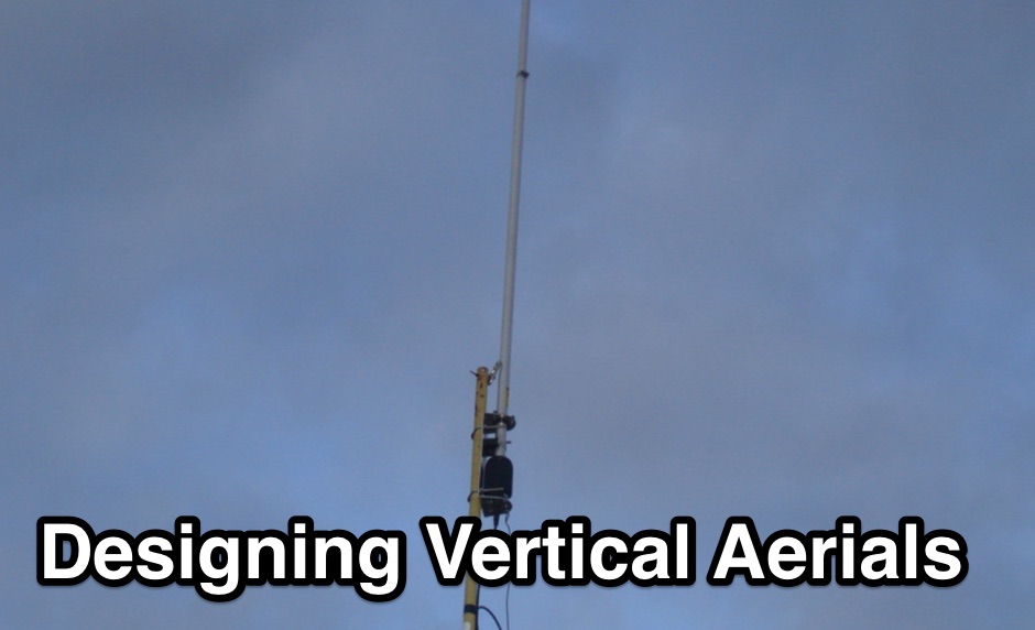 If you want to design vertical antennas you can find all theory and formulas used to model a vertical aerial calculating capacitance, reactance, building the inductor and calculating resistances. Includes an excel spreadsheet to calculate efficiency.
 -
 Describes Atlantic Tower Services (ATS), a company specializing in antenna tower erection and maintenance, operating from Orlando, Florida. ATS offers a range of services including site maintenance, structural repairs, system modifications, and complete tower installations for various communication needs. The company emphasizes its capability to handle diverse tower projects, from routine inspections to complex upgrades, ensuring structural integrity and optimal performance for amateur radio and commercial installations. ATS focuses on delivering reliable infrastructure solutions, supporting the backbone of communication systems. Their service portfolio covers critical aspects of tower ownership, addressing both preventative care and reactive solutions for existing structures. They are equipped to manage projects involving different tower types and heights, adhering to safety standards and operational best practices. Services include **site maintenance** and _structural modifications_.
 -
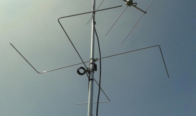 Horizontal polarized omni directional 50MHz Antenna. This antenna is intented to use in a contest station as a second system beside the stacked yagi beam system. An omnidirectional systeem can be an advantage when it comes to short openings on wich the operator must react quickly.
 -
 Dallas County REACT, Inc., is a nonprofit organization of citizens interested in radio communications and committed to public service.
 -
 Demonstrates the construction of a high-power 6-meter (50 MHz) amplifier, specifically designed for demanding modes like EME, TEP, and multiskip Es. It details the use of a _GU-43B_ tetrode in a grounded-cathode configuration, emphasizing the need for stabilized grid voltage and input capacitance compensation. The resource provides a comprehensive schematic, power supply design, and practical considerations for component sourcing, particularly for high-voltage and high-current sections. The builder achieved an output power of **1250 watts** with an anode current of 0.65 amperes and 3200 volts anode voltage. The article also covers the physical construction within a modified P6-31 enclosure, outlining the internal layout for RF and power supply sections, and includes photos of the completed unit. It highlights critical safety precautions for working with high voltages and reactive currents up to **20 Amperes** in the P-network.
 -
 Many antennas and antenna designers neglect the true cause of loss. The major problem using short antennas is the reactance, not the length
 -
 This article describes the construction of a three-band vertical antenna for the WARC bands (10, 18, and 24.9 MHz). Unlike a previous design using thin wire requiring a complex matching device, this version uses a telescopic set of pipes, reducing reactances and simplifying the matching device to two coils and two capacitors. The article provides details on the antenna model, the matching device circuit, and tuning methods, including the use of frameless coils and variable capacitors. With proper tuning, the antenna achieves a VSWR not exceeding 1.3 across all bands, demonstrating a practical and efficient design for amateur radio enthusiasts.
 -
 The Smith Chart, named after its inventor Phillip H. Smith, is a graphic tool used to solve transmission line problems in the field of ham radio operations. By using the Smith Chart, ham radio operators can determine the feed point impedance of an antenna, design impedance-matching networks, and optimize power transfer between a source and its load. The chart consists of resistance and reactance circles, providing a visual representation of complex mathematical relationships related to transmission line operations. Understanding and utilizing the Smith Chart is essential for hams looking to enhance the performance of their RF circuitry.
 -
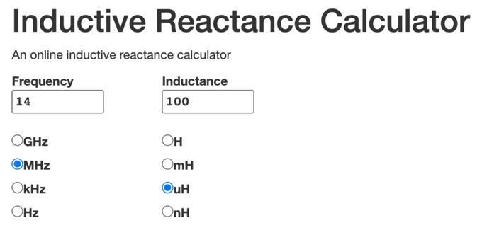 An online inductive reactance calculator, accepts as input Frequency and Inductance
 -
 VE1ZAC's analysis details the performance of **MFJ927** and **SGC239** autotuners with portable HF vertical antennas, specifically comparing 31 ft and 43 ft configurations. The resource originated from challenges encountered during a Maritime QSO Party roving operation, necessitating a lightweight and easily deployable antenna system. Target bands for the contest included 80, 40, 20, 15, and 10 meters, with a maximum power handling of 100 W CW. The author utilized a 30-foot carbon fiber push-up pole to support a vertical wire element, noting its 2 lb weight and reliability. EZNEC modeling was employed to predict performance, showing favorable results for a 30-foot vertical with elevated radials, particularly on 40 and 20 meters. Feedpoint impedance measurements, taken with an AIM4170C, are presented for various HF bands, both with and without a 41-foot RG6 stub designed to reduce reactance on 80 and 20 meters. The stub significantly improved matching on these bands, easing the tuner's workload. Operational tests revealed issues with the MFJ927's reliability during contest setup, leading to reliance on the K3's internal tuner. The SGC239, tested post-contest, performed flawlessly. A detailed side-by-side comparison covers mechanical aspects, connection options, power bias, impedance range, board quality, and documentation. Modifications to the MFJ927, including a new aluminum case, white paint for heat reduction, and upgraded impedance-measuring resistors, are also described.