Search results
Query: roof antenna
Links: 48 | Categories: 0
-
 This resource details the fundamental aspects of deploying longwire antennas, emphasizing ease of construction and installation for shortwave listening (SWL) and broadcast reception. It covers wire gauge selection, suggesting 14 to 24 AWG for general use, with heavier gauges (14-20 AWG) for permanent outdoor installations. Guidance is provided for various deployment scenarios, including indoor setups where the wire can be run around a room, temporary outdoor installations from balconies using light 18-24 AWG wire, and permanent outdoor configurations requiring higher placement and slack for tree movement. Feeding methods are discussed, recommending coaxial cable (50-75 ohms) to mitigate man-made interference, with instructions for connecting only the center conductor to the longwire. Safety precautions are highlighted, particularly avoiding contact with power lines and conductive materials, and managing static electricity buildup by unplugging the antenna after use and bleeding off charges before connection. The article also advises against using outdoor longwires during thunderstorms or snowstorms due to static and lightning risks. Optimal height considerations are presented, advocating for the highest safe placement, ideally a couple of feet above underlying structures, to maintain free air space. The text mentions a personal setup with one end at a roof peak (20 feet) and the other at a 17-foot mast, illustrating practical deployment without strict height requirements beyond safety and clearance.
 -
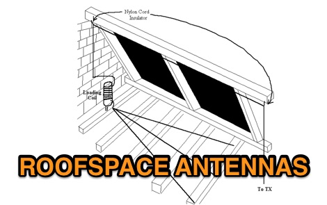 How to build a roofspace antennas and get them to work. Explains how to build an effective antenna in your roof. Very interesting if you don't have possibilities to setup an antenna in your roof.
 -
 Details the construction of a J-vertical antenna specifically for the 10-meter band, offering a practical alternative to a _Slim Jim_ design for 28 MHz. The resource outlines the use of aluminum tubing for the half-wave vertical section and coaxial cable for the quarter-wave matching section, providing specific calculations for element lengths based on frequency and coaxial cable velocity factor. It contrasts the performance of the J-vertical with center-fed dipoles and end-fed verticals, noting superior results in previous comparisons. The article further presents a more recent iteration of the J-vertical, constructed using a fiberglass pole and insulated wire, with updated dimensions for 28.8 MHz. It includes practical advice on weatherproofing connections and securing the antenna for durability against adverse conditions, referencing the survival of an original _J Vertical_ during 110 MPH winds in 1987. The SWR performance is reported as 1.1:1 at 28.6 MHz, maintaining below 1.5:1 across 28.3 to 29 MHz.
 -
 The boomless quad antenna is a unique design that offers versatility for amateur radio operators. This antenna consists of two half-wave dipoles arranged in a square or circular shape, allowing for both vertical and horizontal polarization depending on the feed point. The design facilitates easy installation and rotation, making it suitable for various operating conditions. The construction utilizes strong materials, such as bamboo, and incorporates waterproofing techniques to enhance durability. This project outlines the necessary dimensions and materials, including copper wire and insulators, to successfully build the antenna. It emphasizes the importance of tuning each radiator element for optimal performance. The boomless quad is particularly effective across multiple HF bands, including 14 MHz, 21 MHz, and 28 MHz. By following the detailed instructions, operators can achieve a reliable and efficient antenna setup that enhances their DXing and contesting capabilities.
 -
 Glen Martin manufactures aluminum and steel amateur antenna self-supporting and telescoping towers, mounts, masts, thrust bearings and accessories.
 -
 Presents a practical design for a **crossed-dipole turnstile antenna** specifically engineered for 2-meter Amateur Radio Direction Finding (ARDF) events. The author, WB6RDV, details a robust, omnidirectional, horizontally-polarized antenna, addressing the international ARDF rules requiring such characteristics at a height of two to three meters above ground. This contrasts with the vertical polarization often used in Southern California, highlighting the design's adherence to specific event requirements. The electrical design employs a classic crossed-dipole with a 75-ohm phasing section, resulting in a slight impedance mismatch and an SWR of approximately 1.3:1 with a 50-ohm feedline. Construction utilizes readily available and inexpensive PVC plumbing components and 1/8-inch bronze welding rod for elements. The guide provides step-by-step instructions for mechanical assembly, including drilling element holes at precise 90-degree spacing and preparing the RG-179 matching section. WB6RDV shares insights from his own build experience, discussing the use of plated brass versus aluminum spacers for element attachment and the effectiveness of crimping as an alternative to soldering. The document also covers final assembly, including the integration of ferrite beads as a choke balun and options for weatherproofing and alternative mounting configurations, emphasizing the adaptability of the design for other VHF bands through scaling.
 -
 The 30/40 meter **vertical antenna** project by IK4DCS details the construction of a shortened, self-supporting design, reaching a total length of 5 meters. The antenna incorporates a linear loading section and a coaxial cable trap for 30 meters, based on the "Antenne Volume 2°" text by Nerio Neri (page 223). The design uses six radials, three for each band, positioned at approximately 90° inclination and at least one meter above the roof or ground, connected via a 1:1 balun at the feed point. Mechanical construction utilizes aluminum tubing, with a 2.30-meter primary radiator section (30 mm diameter) joined to a second part using a Teflon insert and a PVC sleeve for rigidity. The linear load, approximately 3.70 meters long, accounts for a 30% physical shortening of the quarter-wave element. A capacitive load, made from three 50 cm radials, is integrated into the 40-meter top section for fine-tuning. Final adjustments involved radial inclination for 40 meters, as initial testing showed increased SWR and interference on 30 meters due to nearby resonant structures. The author emphasizes the importance of clear space for optimal performance and provides drawings and photos to clarify the build process.
 -
 Interesting article on mobile antennas by Cebik. . The article offers advice for setting up and operating mobile antennas for ham radio use. It emphasizes the lossy nature of mobile-in-motion antennas but encourages users to rise to the challenge. Steps include safeguarding car electronics, choosing proper cabling, and carefully selecting and mounting antennas. It highlights potential issues like roof mounting, trunk lip grounding, and side-mounting for trucks. For stationary operation, options like dipoles or beams are explored, with safety tips for masts and guying systems. Lastly, it stresses safety, suggesting stopping the vehicle to operate whenever possible
 -
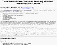 How to make a Weatherproof Vertically Polarised Omnidirectional Aerial, The Slim Jim Antenna
 -
 Antenna support engineering, manufacturer of antenna masts, supports, towers, self-supporting towers, telescopic masts, rooftops and wall supports
 -
 This is a base-loaded vertical antenna that mounts on the car's roof. The loading coil is designed as a variable inductor, with a three-legged chariot that travels up and down inside the coil, with grooved brass wheels running on the coil turns, and driven by a slotted rotor tube.
 -
 N7KSB used this 1/2 watt CW transmitter, with a roof-mounted ground-plane antenna to work all continents and over 30 countries
 -
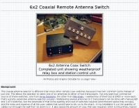 6x2 coaxial remote antenna switch, completed unit showing weatherproof relay box and station control unit.
 -
 The Antenna Rotator Controller is unique in that it senses, displays, and controls to the earth's true magnetic field. The compass sensor, mounted in a waterproof enclosure, is attached to the mast and sends its signal to a microcontroller
 -
 This resource details the conversion of an 80m elevated vertical antenna to include 160m operation, focusing on a relay-switched design over a trap-based approach. It presents specific feedpoint impedance values, such as **32 ohms** for 80m and **14 ohms** for 160m, and discusses the challenges of SWR drift encountered with the prior trap system during RTTY contesting. The article thoroughly explains the design choices for elevated radials, referencing _N6LF QEX data_ to debunk common myths regarding radial length and height, demonstrating that non-resonant radials can offer superior current uniformity. The construction section provides practical insights into building the vertical, including guying strategies, material selection from scrap pipe, and weatherproofing the relay assembly. It highlights the use of a common mode choke for the relay switching line, measuring approximately 5K ohms on both 160m and 80m, and details the L/C matching network's role in achieving a 50-ohm match at the end of a 300-foot RG-11 run. The author describes a precise VNA-based radial trimming procedure, achieving resonant values within a 3 KHz range. The content emphasizes the practical application of theoretical antenna principles, particularly concerning the interaction between the vertical element, cap hats, and the matching network. It offers a candid assessment of component selection, such as using junkbox parts and acknowledging the need for future upgrades to static drain resistors. The article serves as a comprehensive case study for advanced antenna builders tackling multi-band vertical designs.
 -
 Presents a construction project for a linear-loaded 40-meter rotatable dipole, detailing the design evolution from mid-element coils to 300-ohm twinlead loading. It covers material selection, including repurposed fishing poles and EMT conduit, and outlines the assembly process for the antenna elements and mounting plate. The resource provides specific measurements for element lengths and linear loading sections, along with SWR plots demonstrating the antenna's resonance at 7.035 MHz with a 1.1:1 SWR, and bandwidth up to 7.120 MHz below 2:1 SWR. The article documents the antenna's performance during various RTTY and CW contests, including the SARTG RTTY and SCC RTTY contests in August 2006, and the ARRL DX CW and CQWW WPX RTTY contests in February 2007. It reports successful operation at 500-1000W, noting improved performance after replacing a faulty coax cable. Specific DX contacts from British Columbia, including stations in Europe and South Africa, are listed, illustrating the antenna's capability despite its shortened length and relatively low height of 55 feet. The content highlights practical considerations such as weatherproofing the connections and supporting the fiberglass elements to prevent sagging. It also includes a brief comparison to an inverted-V at similar height and a ground-mounted vertical, noting the rotatable dipole's quieter reception. The author shares insights into the iterative design process and tuning adjustments made to achieve optimal resonance.
 -
 Demonstrates the construction and implementation of a **two-element phased vertical array** for 40 meters, utilizing _Christman phasing_ techniques. The author, W4NFR, details the process from building individual 1/4-wave aluminum verticals to integrating them into a phased system. The resource covers antenna spacing of 32 feet, elevated radial design, and the critical steps for tuning each vertical to achieve a 1.1:1 SWR before combining them. It also provides insights into calculating precise coax lengths for feedlines and the phasing delay line, emphasizing the use of an MFJ-269 Antenna Analyzer for verification. The finished system exhibits good front-to-back nulls, with an overall SWR ranging from 1.6:1 to 2.2:1, which is managed by an antenna tuner. The project includes detailed photos of the relay box, showing 12 VDC relays capable of handling 5KV, and the control box in the shack for switching between three different antenna pattern configurations. Static bleed-off chokes are incorporated for protection, and the construction emphasizes robust weatherproofing for outdoor elements.
 -
 Sherwood Engineering Inc. (SEI) offers a repository of technical presentations and white papers focused on optimizing amateur radio transceiver and receiver performance. Content includes detailed analyses of _roofing filters_, transmitted IMD, and receiver characteristics, with specific discussions on products like the Drake R-4C and Icom IC-781. Presentations from events such as Dayton Contest University (2008-2014) cover topics like "How To Optimize Rig Performance," "Transceiver Performance: 10 Years of Change," and "Choosing a Transceiver: Far from Simple." Additional white papers address HF mobile antenna efficiency, ground screen alternatives to buried radial systems, and common receiver problems with solutions. The site also provides historical product information for items like the SE-3 MK IV synchronous AM detector and various 455 kHz mechanical and crystal filters, though many products are no longer in production. Receiver test data and alignment tips for the R-4C are also available, offering insights into rig modifications and performance enhancements.
 -
 This article compares two commercial vertical antennas for the 4-meter amateur radio band: the Watson WVB-70 half-wave and the Sirio CX4-71. The Watson measures 2.03m in length, costs around £40, and exhibited adequate performance but required additional waterproofing after rain affected its VSWR readings. The longer Sirio CX4-71 (3.02m) performed noticeably better, delivering signals approximately 2 S-points stronger than the Watson. The Sirio demonstrated high build quality, a stable 1.2-1.4:1 VSWR, and weather resilience, though minor VSWR fluctuations were observed during rain and frost. Both antennas are half-wave designs requiring no ground plane radials.
 -
 Mounting on Roof or at Ground Level? Why ground plane antenna works better at lower level.
 -
 Manufacturing distributor of infrastructure products for the telecommunications industry; antenna mounts, ice bridge, cable ladder, ground bars, weatherproofing, exothermic, safety equipment.
 -
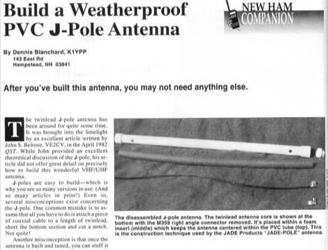 After you have build this antenna, you may not need anything else. This article shows how to build a VHF j-pole antenna and how to protect it by inserting it into a PVC tube, the correct way.
 -
 K1JJ presents a compilation of insights regarding vertical radial ground systems, specifically applied to 160m vertical arrays. The resource details 19 distinct observations and recommendations, emphasizing that ground radials primarily reduce ground losses rather than influencing pattern formation. It explains that RF current flows inefficiently through average soil, necessitating copper radials to create a low-resistance path back to the antenna base. The content suggests that **50-60 radials** are generally sufficient to achieve optimal efficiency, with diminishing returns beyond that number, and that radials should be laid on the surface for best performance. The discussion also addresses practical aspects such as wire gauge, installation techniques using 'U' shaped staples, and methods for connecting radials in multi-element arrays. It highlights the importance of radial length, stating that 1/4 wave radials are a crucial minimum, and that for 160m, radials should be at least _100 feet_ long. The resource critically examines the efficacy of elevated radials versus ground radials, noting that while a few elevated radials may suffice for VHF, HF applications, particularly on 160m, require extensive ground radial systems to efficiently collect RF currents in the near field. It also touches on the impact of radial systems on parasitic elements and the significance of symmetrical radial patterns for minimizing losses. Further practical advice includes wire type recommendations, proper soldering and weatherproofing techniques for radial connections, and considerations for integrating steel towers into the ground system. The author shares personal experience with installing 60 quarter-wave and half-wave radials under each of three in-line verticals, expressing satisfaction with the results.
 -
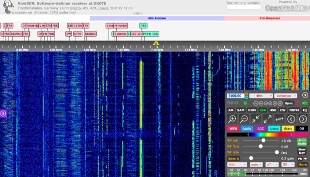 Online internet HF LW MF web receiver based in Baden-Wuerttemberg cooperative state university Ravensburg Campus Friedrichshafen running a T2FD antennan under roof.
 -
 Experimenting OCF and dipole wire antennas over house roof. Effects of roofs on wire antennas
 -
 The Eastman Amateur Radio Club (VE4TG) operates a **VHF repeater** at 146.73 MHz and a **UHF repeater** at 444.15 MHz, both located at the Manitoba Hydro gas-fired generating station near Selkirk. These repeaters are situated on the power plant roof, leveraging its infrastructure for antenna placement. The club's primary objective is to offer a reliable local repeater site for members in the East Selkirk and Lockport areas, ensuring consistent amateur radio access. Beyond routine communication, the club maintains a standby communications link to assist local municipal authorities during emergencies requiring communications support. The unique repeater site location at a generating station provides a robust backup power supply, enhancing reliability. The club also organizes activities such as a weekly net and participates in WARC Field Day, fostering community engagement and operational readiness.
 -
 Accurate meteorological data is crucial for optimizing antenna performance, predicting propagation, and ensuring safe tower work. This resource provides a curated inventory of weather stations, including models like the _AcuRite Atlas_ with lightning detection and the _Ambient Weather WS-2902_ WiFi Smart Weather Station, which offer real-time data on environmental factors. The product listings detail specific features such as direct-to-Wi-Fi connectivity, rainfall tracking, and temperature insights, enabling informed decision-making for various amateur radio operations. The platform categorizes products by application, featuring weather stations tailored for home and backyard use, as well as more robust systems for farm and agriculture, which can be critical for field day operations or remote station monitoring. It also highlights _Made in USA_ options, emphasizing local manufacturing and support. Beyond weather instruments, the site also presents related surveillance technology, such as the _Waggle solar CCTV camera_, designed for outdoor reliability with an IP65 weatherproof rating. This integration allows for comprehensive monitoring of remote ham radio shacks or antenna sites, combining environmental data with visual oversight.
 -
 MARCA, Inc. operates approximately 24 repeaters across Arizona mountaintops and Phoenix-area rooftops, supporting modes like D-STAR and Fusion. The club, holding the **W7MOT** callsign, engages in diverse activities including ARRL Field Day events near Forest Lakes, AZ, ARRL FMT contests, and antenna experimentation. Members actively participate in HF operations such as voice, digital, CW, DXing, and various digital HF modes, alongside MESH and EOC operations within the valley. The club's interests span a broad technical spectrum, from SDR radio building to antique radio restoration, and include modern digital modes like WSPR, WSJT, FT8, and FT4. They also explore computer-based operations such as Echolink, fostering a dedicated Single Board Computer (SBC) and Raspberry Pi group. Monthly VE testing sessions for Technician, General, and Extra Class licenses are conducted by Ray Vasquez, K4RMV. Meetings are held on the third Tuesday of each month, typically lasting two hours, with a business segment followed by a technical presentation. These gatherings occur in-person at IHop in Mesa, AZ, and concurrently via Zoom, accommodating both local members and winter visitors. Informal chat groups often form post-meeting to discuss specialized topics like D-STAR, SDR, APRS, MESH, and Fusion.
 -
 The DIY 137 MHz WX SAT V-dipole antenna project details the construction of a specialized antenna for receiving weather satellite transmissions. It provides specific dimensions for the dipole elements, designed for optimal reception around the 137 MHz band, which is commonly used by NOAA and Meteor weather satellites. The resource outlines the materials required, such as aluminum tubing for elements and PVC for the support structure, along with the necessary coaxial cable and connectors. The article presents a clear, step-by-step assembly process, including how to form the V-shape and connect the feedline. It emphasizes practical considerations for mounting and weatherproofing the antenna for outdoor deployment. The design focuses on simplicity and effectiveness for amateur radio operators interested in satellite imagery. Key aspects include the precise angle of the V-dipole and the lengths of the radiating elements, which are critical for achieving the desired circular polarization response for satellite signals. The resource includes photographic documentation of the construction phases and the final mounted antenna.
 -
 The ARRL's End-Fed Half-Wave (EFHW) Antenna Kit is an easy-to-build four-band antenna designed for 10, 15, 20, and 40 meters. Ideal for portable operations, it includes a 49:1 impedance transformer for compatibility with most transceivers. This project, detailed with step-by-step assembly instructions, involves creating a weatherproof enclosure and impedance matching network. The kit simplifies HF operations and supports multiple configurations, making it a versatile tool for amateur radio opertors.
 -
 A magnetic loop antenna designed for 14 MHz. This kind of antennas is also known as STL, small transmitting loop and can be an excellent solution when you are not allowed to put antennas on your roof
 -
 The Linked Dipole is a multiband antenna designed for 80/60/40/30/20m bands, optimized for the (tr)uSDX low bands configuration. It incorporates a 1:1 Balun to prevent common mode currents, ensuring balanced operation with coaxial cable. The Balun, wound on an FT140-43 core, achieves 37-40dB attenuation. The design includes a 3D-printable housing for compactness and waterproofing, with labeled link insulators for ease of use. Wire lengths were meticulously adjusted for optimal performance with a 7m pole and 3m rope extension, ensuring the antenna's ends are off the ground for improved behavior. The project includes downloadable printables for DIY construction.
 -
 This article provides a detailed guide on how to build a no holes roof mount for ham radio antennas. The author shares their design that can hold 2 masts and offers tips on installation. The mount is versatile and can handle small 144 Mhz or 432 Mhz beams, as well as small verticals. With adjustable angles and spacing, the mount can be customized to fit different roof types. Additionally, the author suggests affordable options for obtaining Dish antenna mounts. Overall, this DIY project offers a cost-effective solution for ham radio operators looking to mount antennas on their roofs.
 -
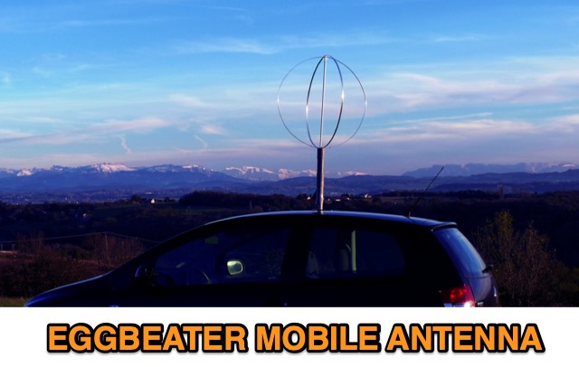 The eggbeater antenna uses on mobile operations using the metal roof of the car as the reflector. The distance between the antenna and the roof as described in this article should be 1/8 lambda.
 -
 Operating in antenna-restricted communities presents unique challenges for amateur radio operators, often necessitating creative solutions for antenna deployment. This resource details the design and implementation of stealth antennas within a townhouse community in Exton, PA, where external antennas were strictly forbidden by covenants. The author, WB5NHL, describes his setup, which involved locating the shack in the basement and utilizing an unused space under the roofline of a finished third-floor loft for antenna placement. The content specifically addresses the practicalities of routing coax cables three floors and maximizing antenna performance within limited attic space. It covers solutions for multi-band operation, including dedicated sections for 40-10 meter and 80-meter antennas, along with strategies for mitigating potential interference issues. The approach emphasizes full compliance with community covenants, achieving maximum height-above-ground for horizontal antennas, enabling instant band switching, and efficiently utilizing available attic volume. While acknowledging limitations such as potential interference with high power and fixed antenna patterns, the resource provides a detailed account of a functional compromise for restricted environments. Links to individual pages on _coax cables_, _40-10 meter antennas_, _80-meter antennas_, and _interference issues_ offer deeper dives into each specific aspect of the installation.
 -
 Mounting on roof at the right ground level can greately impact on antenna performances because will affect the radiated angle of energy.
 -
 The U01 emergency communications antenna is a versatile, multiband antenna designed for 80/60/40/20/17/15/10m bands, known for its reliability and compact size. It features a broadband transformer wound on various core options like FT82-43, FT114-43, or FT140-43, with the latter capable of handling up to 100W. The antenna incorporates a PCB with options for SMA and BNC connectors, and a weather-proofed design for durability. The lightweight construction, using materials like DX Wire UL and Polyester rope, makes it highly portable. The antenna's design has been tested and proven within the DARC Chapter U01, with multiple build options and detailed documentation available for DIY enthusiasts.
 -
 A Trapped dipole inverted V antenna for lower HF Bands. Construction details are for temporary installation. Permanent installations will require additional ruggedising and waterproofing however the basic electronics concepts remain the same. This project includes SWR plots for the three bands and pictures details of the homemade traps.
 -
 The mini Radio Solutions miniVNA PRO is the only affordable vector network analyser (VNA) I know of that offers remote wireless operation. This is very interesting because it allows to measure the input impedance of HF antennas installed at height without having to deal with coax cable lengths, baluns nor common mode suppression chokes. However, to render the miniVNA PRO truly field proof, it requires a number of significant modifications.
 -
 SkyRoof is an open-source, 64-bit Windows application designed for amateur radio operators and satellite enthusiasts, combining satellite tracking and Software Defined Radio (SDR) functionality in a unified platform. The software provides real-time satellite tracking, pass predictions, and visual representations through Sky View, Earth View, and Timeline displays. It features an SDR-based waterfall display covering VHF/UHF satellite segments with Doppler-corrected frequency scales, automatic satellite labeling, and visual tuning capabilities. SkyRoof supports various SDR devices (Airspy Mini, SDRplay, RTL-SDR), external transceiver CAT control, and antenna rotator integration. The application automatically downloads satellite data from SatNOGS and other sources, offers voice announcements for satellite passes, and includes comprehensive frequency control with Doppler tracking, manual corrections, and RIT functionality for enhanced satellite communication operations.
 -
 The article details the design and construction of a four-band Moxon beam by a radio amateur. The beam, mounted atop a rooftop tower, aimed for gain over a dipole on 20 meters, cost under $500, and included additional bands. The design features fiberglass spreaders, four bands (20/15/10/6 meters), and a single feedpoint. The construction involved computer modeling, NEC source code, and specific dimensions. The article outlines the assembly, materials, and tuning process, including in-situ adjustments for optimal performance. Despite initial challenges, the beam improved signal strength and facilitated contacts on multiple bands, marking it as the best HF antenna the author has owned.
 -
 This DIY homebrew project provides a durable, weatherproof center connector for dipole antennas, ideal for HF setups like 40m wire dipoles or inverted-V designs. Made from PVC pipe and an SO-239 UHF connector, it ensures strong support and room for a current balun. With simple drilling and assembly, it offers a cost-effective alternative to commercial options. Perfect for amateur radio operators, this dipole antenna connector enhances performance while keeping costs low. A great solution for DIY antenna builders seeking reliability and longevity.
 -
 Presents a detailed construction guide for a 9 dB, 70cm collinear antenna, utilizing readily available _RG58/U_ coaxial cable and PVC pipe for housing. The resource outlines the critical calculations for ½ wavelength sections at 444 MHz, incorporating the coaxial cable's velocity factor of 0.66, which yields a section length of 223 millimeters. It specifies the preparation and soldering of eight such half-wavelength sections, each cut to 231mm to allow for trimming, forming the core of the array. Further instructions detail the integration of a ¼ wave element (169mm #16 solid wire) at the top and a ¼ wave aluminum tube (160mm, 5/16 inch) at the bottom, crimped to the feed point's braid. The guide also addresses RF common mode current suppression by suggesting the use of _FT50-43_ toroids on the feedline. Final assembly steps cover mounting the antenna within ¾" PVC pipe using a wooden dowel, waterproofing connections, and initial SWR checks. The article also discusses scaling the design for different element counts and other VHF/UHF bands.
 -
 Learn how to build a compact and efficient HF antenna for ham radio operators with limited space. Follow the author's journey from experimenting with different antennas to creating a magnetic-mounted antenna that covers 7MHz to 30MHz without the need for an ATU. Discover how a portable flagpole can be repurposed for radio communication, allowing you to operate with 100 Watts power output. This project provides a cost-effective solution for hams looking to set up a reliable antenna on their car roof in just 30 seconds.
 -
 This document provides comprehensive guidance on modeling and constructing multiband dipole antennas using traps. It addresses common segmentation issues in EZNEC modeling software, recommends optimal segment lengths for trap models, and compares trapped dipoles with paralleled multiband dipoles. While trap dipoles are significantly shorter, they exhibit lower gain and narrower bandwidth. Detailed instructions for building weatherproof coaxial traps include material lists, construction steps, and tuning methods. The guide notes that properly constructed coaxial traps introduce only minimal signal loss (0.6 dB) while offering practical multiband performance in a compact design.
 -
 When installing a mobile antenna, optimal placement significantly impacts performance. Factors such as gain, antenna type, ground plane availability, mounting style, and environment must be considered. Antenna designs, such as 1/4 wave and 5/8 wave, have distinct radiation patterns ideal for specific settings—urban areas or flat terrains, respectively. Ground plane size requirements differ by frequency, impacting effectiveness. Among vehicle mounting options, the car roof center provides the best ground plane and minimal obstruction, ensuring peak performance, especially at higher frequencies like 800 MHz.
 -
 Moto-QRP setups offer compact, weatherproof QRP transceivers for portable ham radio use, ideal for motorcycle and backpack operations. The YouKits HB1A MKII, a 5W CW rig, is paired with a lightweight long-wire antenna and an Elecraft T1 tuner for efficient field communication. This setup fits in panniers, enabling operators to explore parks and remote locations. Accessories include a durable Morse paddle, FCC documentation, and essential logging tools, making it a perfect choice for adventurous QRP enthusiasts.
 -
 The 4m Slim Jim antenna project provides a construction guide for a low-cost, high-performance aerial designed specifically for the 70 MHz FM band. This design achieves a 1:1 SWR across the 4m FM band with straightforward adjustment of the feed point, utilizing RG-58 coax. Its low angle of radiation contributes to effective signal propagation. Construction involves using plastic knitting needles as spreaders and a telescopic fishing pole for support, with components secured using two-part epoxy. Annealed bare single-core copper wire forms the radiating element. The setup process includes raising the antenna at least 3 meters above ground for tuning, adjusting the RG-58 feed point for optimal SWR, and then soldering connections. Waterproofing is achieved with yacht varnish. The design emphasizes low wind resistance for durability, making it suitable for exposed outdoor installations. A PDF construction diagram is available to supplement the written instructions.