Search results
Query: standing wave
Links: 54 | Categories: 2
-
 This resource provides a detailed guide on constructing a J-pole antenna specifically for the 2 meter band, which is popular among amateur radio operators. The article outlines the materials needed, including various sizes of aluminum pipes and PVC, as well as the tools required for assembly. It emphasizes the simplicity and effectiveness of the J-pole design, making it an ideal choice for newcomers to amateur radio. The instructions are straightforward, allowing users to build the antenna in less than an hour, and include tips for tuning the antenna for optimal performance. In addition to the construction details, the resource includes practical advice on the assembly process, such as how to cut and join the pipes, as well as how to mount the SO239 connector. The author shares personal experiences and insights on achieving a low standing wave ratio (S.W.R.) and suggests modifications for creating bi-band or tri-band J-pole antennas. This comprehensive guide is enriched with photographs that illustrate the construction steps, making it easier for users to follow along and successfully build their own J-pole antenna.
 -
 GM4JMU shortened dipole for 40 meters band. This article illustrates in detail how to build a resonant antenna for 7.030 MHz. Cut two 10.25-meter pieces of insulated wire, wind 40 turns of wire onto plastic tubing, and connect the wire to a central insulator using a choke balun built of RG174AU coax and a ferrite toroid. Once built, the antenna is adjusted by altering the wire length to produce the lowest Standing Wave Ratio (SWR) for best performance. The guide emphasizes careful building and adjustment for the best results.
 -
 Determining the actual need for an antenna tuner often hinges on the specific antenna and feed line configuration in use. While many hams believe a tuner is always essential, its primary role is to present a 50-ohm impedance to the transceiver, not to "tune" the antenna itself. For instance, a resonant dipole fed with _coaxial cable_ at its design frequency typically requires no tuner, as the feed line impedance closely matches the radio's output. However, operating a non-resonant antenna, or using a resonant antenna on multiple bands, frequently necessitates a tuner to manage high Standing Wave Ratio (SWR) on the feed line. The article clarifies that a tuner placed at the transceiver only matches the radio to the feed line, not the antenna to the feed line. For maximum efficiency with a non-resonant antenna, an _automatic antenna tuner_ (ATU) or a remote tuner placed at the antenna feed point is often more effective, minimizing losses in the feed line. The discussion also touches on the practical implications of SWR, noting that modern transceivers often fold back power at high SWR, making a tuner a practical necessity to achieve full output power, even if the antenna itself is not perfectly matched.
 -
 The project details a DIY SWR/Wattmeter designed around an _Arduino Uno_ shield, providing capabilities to measure RF power from 2 to **200 watts** and Standing Wave Ratio (SWR) for HF amateur radio bands. This construction features a compact design, integrating the measurement circuitry directly onto a custom PCB that interfaces with the Arduino Uno microcontroller. Key components include a directional coupler for sensing forward and reflected power, precision rectifiers, and analog-to-digital conversion for processing RF signals. The Arduino firmware handles calibration, calculations, and displays the results on an integrated LCD, offering real-time feedback on antenna system performance. The design prioritizes simplicity for homebrewers. Performance specifications indicate accurate readings within the **2-200W** power range, suitable for typical QRP to medium-power HF operations. The project provides schematics and a basic overview of the software logic.
 -
 We worry a lot about Standing Wave Ratio (SWR) in amateur radio since SWR is one indication of how well our antenna system is working. Most HF transceivers and antenna tuners have built in SWR meters. SWR is a measure of a transceiver' s output power verses the portion of that power reflected by the antenna system
 -
 Presents the product lines and corporate information for Japan Radio Company (JRC), a long-standing manufacturer of radio communication equipment. The company's offerings span various sectors, including marine, land, and aviation communication systems, alongside their historical contributions to amateur radio with notable **HF transceivers** and **shortwave receivers**. JRC emphasizes its technological expertise in areas such as radar, satellite communication, and network solutions, contributing to global safety and security infrastructure. The resource details JRC's commitment to leveraging its accumulated knowledge and experience in information and communication technology. While the primary focus has shifted towards commercial and governmental solutions, the legacy of JRC's amateur radio products, such as the JRC JST-245 transceiver and the NRD-525 receiver, remains significant within the ham radio community, known for their robust build quality and performance.
 -
 Over 45 years of amateur radio experience inform the homebrew projects detailed on this personal website, with a particular focus on microwave frequencies. The site showcases a 24 GHz transverter and a more recent 47 GHz transverter, demonstrating practical construction techniques for extreme high-frequency operation. These projects often involve custom circuit design and careful component selection to achieve stable performance at millimeter-wave bands. Key projects include a _harmonic converter_ for frequency measurement and a tracking spectrum analyzer, essential tools for microwave experimenters. The site also documents a CW sidetone generator and a TX/RX sequencer, illustrating fundamental building blocks for radio equipment. Details on a digital frequency meter and an S-meter/dBm meter provide insights into test equipment construction. Specific achievements, such as a **24 GHz** tropo QSO with DK3SE in 2021, highlight the operational success of these homebrewed systems. The content reflects a long-standing dedication to self-sufficiency in amateur radio, providing practical examples for those interested in building their own gear.
 -
 The page provides detailed instructions on how to build a double bazooka antenna for the 40 meters band. It includes information on materials needed, measurements, and assembly steps. The antenna can be configured as an extended dipole or an inverted V, offering low noise, wide bandwidth, and a 1:1 standing wave ratio. The content also offers calculations for other bands and includes photos of the antenna fabrication process.
 -
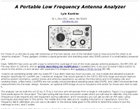 A Portable Low Frequency Antenna Analyzer, For those of us who like to play with antennas on the ham bands, one of the handiest tools to have around the shack is an "antenna analyzer". These gadgets combine a signal generator and standing-wave ratio (SWR) sensor in a small battery-powered unit.
 -
 Theory, Modeling, and Practical Applications By W5JCK, presentation in PDF File. This presentation focuses on Near-Vertical Incidence Skywave (NVIS) antennas, which are crucial for short-range radio communications, particularly in military and emergency contexts. It explores NVIS theory, antenna models, and installation criteria while debunking common myths about reflectors. Key topics include usable frequency bands, optimal installation heights, and the impact of soil quality on performance. The presentation outlines the best bands for daytime and nighttime use, emphasizing the importance of understanding propagation characteristics to enhance communication effectiveness within 200 to 300 miles.
 -
 Understanding high-frequency (HF) skywave propagation is crucial for amateur radio operators seeking to optimize long-distance communications. This resource details the fundamental principles of HF radio propagation, including the properties of electromagnetic waves, the characteristics of various HF bands, and distinct propagation modes such as skywave, ground wave, and line-of-sight. It places significant emphasis on the ionosphere's pivotal role in refracting HF waves, explaining how solar activity directly influences ionospheric conditions and, consequently, propagation paths. The resource integrates real-time monitoring capabilities, featuring dynamic charts and data from DX clusters, WSPRnet, and the Reverse Beacon Network, which allow users to track current band activity and propagation conditions globally. It also delves into advanced topics like Near Vertical Incidence Skywave (NVIS) and gray line propagation, providing insights into ionosonde data and various propagation prediction models. The site presents a detailed analysis of solar-terrestrial interactions, geomagnetic indices, and space weather phenomena, illustrating their direct impact on HF communication reliability. Practical tools and applications are highlighted, including real-time QSO planners, online Maximum Usable Frequency (MUF) maps, and alerts for solar flares or geomagnetic storms. The guide systematically breaks down complex concepts into accessible chapters, offering a structured approach to learning about ionospheric regions, diurnal and seasonal effects, and the interpretation of propagation indicators like foF2, MUF, and Lowest Usable Frequency (LUF). This makes it a robust reference for hams aiming to deepen their technical understanding and improve operational effectiveness.
 -
 Progress in Design of Extremely Short Transmitting Antennas Short and still efficient, how is that possible? By Juergen Schaefer, DL7PE author of the MicroVert antenna concept. The MicroVert introduced in this document is an extremely short and hardly visible short-wave antenna with outstanding radiation properties
 -
 Computes the Standing Wave Ratio, given the power readings on a line.
 -
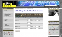
 This calculator is designed to give the efficiency loss of a given antenna, based on the input of VSWR (voltage standing wave ratio) and other subsequent factors
 -
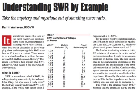 Take the mystery and mystique out of standing wave ratio. QST Article by K5DVW
 -
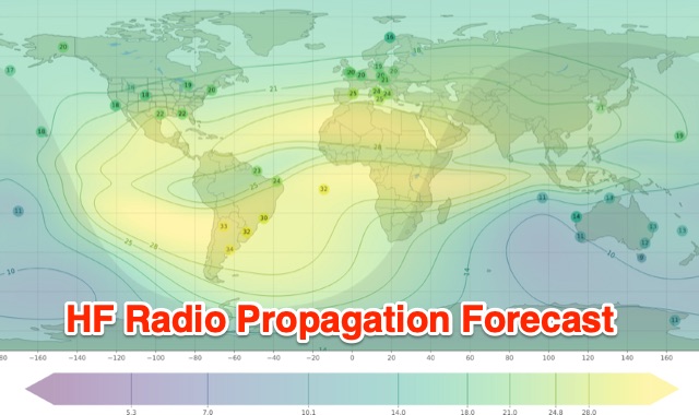
 Flash Movie describing HF (shortwave) radio propagation to beginners. Very helpful aid in understanding.
 -
 50 MHz meteor scatter offers a unique opportunity for amateur radio operators to make long-distance QSOs, even when the band appears dead. Meteor scatter involves reflecting radio waves off the ionized trails left by meteors burning up in the upper atmosphere, typically around 105 km high. These trails can facilitate contacts over distances up to approximately 2,300 km. The technique is particularly effective during meteor showers, which increase the number of meteors and thus the chances of successful QSOs. However, random meteors can also be used to achieve contacts, especially on the 50 MHz band, where the longer reflection time compared to 144 MHz makes it easier to work meteor scatter. Operators should be prepared to make QSOs in short bursts, often lasting only a few seconds. The IARU Region 1 meteor scatter procedure recommends using 2.5-minute periods for telegraphy and 1-minute periods for SSB, though shorter periods can be arranged. For 50 MHz SSB, 15-second timing is often used to maximize the chances of completing a contact. The procedure involves specific timing for transmissions based on direction and requires both operators to confirm receipt of callsigns and reports to complete a QSO. Understanding the geometry of meteor scatter, including the optimal radiation angles and the concept of 'hot spots,' is crucial. These hot spots are areas where reflections are most likely to occur, influenced by the Earth's rotation and the path of the meteors. Proper antenna setup, including elevation control and beam direction, can significantly enhance the chances of successful meteor scatter QSOs.
 -

-
 Deploying robust antenna infrastructure for both fixed and portable operations often requires specialized support structures capable of withstanding environmental stresses while providing optimal radiating element placement. SMC offers a range of solutions, including pneumatic masts and push-up masts, designed to facilitate rapid deployment and reliable long-term support for various antenna types. Their product line encompasses antenna mounts, poles, and complete antenna systems, addressing the critical need for stable and efficient RF communication. The company's offerings extend to HF antennas, including dipoles and _NVIS_ (Near Vertical Incidence Skywave) antennas, which are crucial for short-range regional communications on bands like 80m and 40m. These systems are engineered for durability and performance, ensuring signal integrity across diverse operating conditions. With over **65 years** of experience, SMC has established itself as a global manufacturer in this niche. Their product portfolio also includes antenna support towers, catering to more permanent installations requiring significant height and load capacity for multiple arrays.
 -
 SWR (standing wave ratio), is a measurement of how efficiently your antenna system will radiate the power available from your radio. In simple terms, your radio would like to radiate all of its power, but can only do so if the other components cooperate
 -
 Shortwave listeners and amateur radio operators interested in _numbers stations_ can engage with this mailing list, which serves as a platform for discussing the enigmatic transmissions. The resource facilitates the exchange of information regarding these unusual broadcasts, often associated with intelligence agencies, by allowing members to share observations, decode attempts, and theories. It provides a community space for those who monitor the HF spectrum for these unique, often automated, voice or digital signals. Participation on the list enables members to contribute to a collective understanding of numbers station activity, including changes in frequencies, broadcast schedules, and message formats. While specific technical analysis or signal processing techniques are discussed by members, the primary function is information sharing. The list is administered by csmolinski at blackcatsystems.com, and prior postings are archived for reference, allowing new members to review historical discussions and data.
 -
 The **KC0KJF** personal amateur radio page provides a collection of resources for fellow hams, particularly those interested in operations within southwest Missouri. It offers detailed listings for **Missouri repeaters** on both 2 meters and 70 centimeters, serving as a practical reference for local VHF/UHF communication. The site also includes information about the operator's station setup and antenna projects, such as a dipole and a bazooka antenna, which can offer insights into basic antenna construction and deployment. Beyond local repeater data, the page features links to the FCC Part 97 rules, essential for understanding amateur radio regulations. The operator, licensed as a Technician Class since April 16, 2001, shares his journey from Citizen's Band Radio to amateur radio, driven by a lifelong fascination with shortwave listening. This narrative provides context for the resource's focus on practical operating information and foundational regulatory knowledge. Additional content covers specific equipment like the 2-meter/70-centimeter Arrow Antenna, useful for hams considering portable or fixed station VHF/UHF setups.
 -
 This resource provides a unique historical audio archive of 50 MHz DX contacts, documenting significant F2 and Es propagation events experienced by PA2S (formerly PA2HJS) since 1978. The collection includes recordings of beacons and two-way QSOs with stations across North America, South America, Asia, Australia, Europe, and Africa. Specific entries detail contacts with rare DX entities such as ZS6PW, VE1AVX, C5AEH, J52US, TR8CA, LU8MBL, VK8ZLX, and various Japanese stations, often noting the mode (SSB or CW) and propagation type. The archive also highlights challenging pile-up situations and frustrating near-misses during major openings. The recordings, initially in RealAudio format for solar cycles 21 and 22 and later in MP3 for cycle 23, offer a practical illustration of 6-meter band conditions over several solar cycles. The content allows hams to listen to actual signals from different continents, observing signal characteristics like typical TEP fading from 5H3RA or strong F2 backscatter from OZ1BVW. It provides a comparative perspective on propagation effectiveness between solar cycles, noting that cycle 23, while not as robust as previous cycles, still yielded interesting openings. The archive serves as a valuable educational tool for understanding real-world 50 MHz DXing and propagation phenomena.
 -
 Introduction to Shortwave Antennas. Understanding Shortwave Radio Listening and Antenna Design and Construction
 -
 VHF UHF Microwave EME Standings, a Who's Who on top in USA
 -
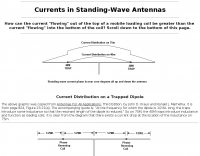 How can the current "flowing" out of the top of a mobile loading coil be greater than the current "flowing" into the bottom of the coil?
 -
 BeaconSpot.uk provides an accurate, real-time picture of microwave and VHF/UHF beacons operating across Europe, alongside a worldwide listing of 6-meter beacons. The platform allows users to retrieve detailed data for individual beacons, facilitating in-depth analysis of signal characteristics and propagation paths. Interactive maps visualize beacon distribution by frequency band and display spot coverage for each station, offering a clear geographical overview of active beacons. The system integrates real-time DXCluster spots, sourced from contributors like Alain, ON4KST, and Pascal, F5LEN, and enables users to submit outgoing spots directly to the DXCluster. Beacon keepers can manage their beacon data, receive email alerts upon being spotted, and track their station's ODX (Outstanding DX) records. For every received spot, the distance to the beacon is automatically calculated and displayed, aiding propagation studies.
 -
 1.5 dB of matched line loss can be calculated for a given transmission line using this online tool, which employs a model calibrated from empirical data. The calculator allows radio amateurs to input specific transmission line types, such as _RG-8_ or _RG-58_, and then determine the expected signal attenuation. This is crucial for optimizing antenna system efficiency and understanding power delivery to the radiating element, especially for HF and VHF operations where feedline losses can significantly impact performance. Beyond matched loss, the calculator also provides an estimate for mismatched loss if the Standing Wave Ratio (SWR) is specified. This feature helps operators quantify the additional power loss due to impedance discontinuities between the transceiver, feedline, and antenna, which is a common concern in amateur radio installations. Accurate loss calculations are vital for effective station design and for predicting actual radiated power. The tool's utility extends to various operating scenarios, from fixed station setups to portable deployments, aiding in the selection of appropriate feedline lengths and types to minimize signal degradation. Understanding these losses is a fundamental aspect of maximizing the effectiveness of any amateur radio antenna system.
 -
-
 About experiments and measurements on loading coils using net standing wave current
 -
 Operating where independent media is suppressed, _Radio Free Europe/Radio Liberty_ (RFE/RL) delivers news and information in 27 languages to audiences in 23 countries. This resource primarily functions as a news portal, focusing on geopolitical events, regional conflicts, and human rights issues, particularly in areas like Ukraine, Russia, Iran, Afghanistan, and Central Asia. It features articles, videos, podcasts, and photo galleries, covering topics such as international relations, energy politics, and the impact of conflict on civilian populations, often highlighting the perspectives of local journalists and freelancers in challenging environments. The content frequently addresses the operational context of shortwave broadcasting, though the site itself is a digital news platform. For example, it details the implications of long-distance strikes and regional military capabilities, which are relevant to understanding the strategic importance of various communication methods. The resource also provides insights into the challenges faced by populations in areas with limited access to uncensored information, underscoring the role of independent news organizations in providing alternative narratives.
 -
 Maintaining vintage Eddystone receivers often presents unique challenges, as detailed by Victor Jenkins in his refurbishment of an EA12, where his deep understanding of RF circuits ensures optimal performance for daily shortwave listening. Similarly, Gerry O’Hara VE7GUH, a prolific contributor to the EUG website and a trustee, meticulously documented his restoration of an Eddystone S830/2, even addressing an unusual instability issue with a follow-up postscript article and YouTube videos demonstrating the fix. His work, along with numerous other articles on the "Restorations" page, showcases a master's approach to bringing vintage sets back to factory specifications or better. Beyond technical restorations, the EUG also shares compelling historical narratives. One such story recounts the discovery of a long-lost 78rpm recording featuring Eddystone Radio Ltd.'s founder, George Stratton Laughton, and other key figures discussing the company's wartime and post-war contributions to shortwave communications. This six-minute BBC production, transcribed into an MP3 file by Peter Carney, offers a rare auditory glimpse into the company's legacy, highlighting its role in supplying equipment to police, ministries, and expatriate British workers. The community aspect thrives through shared experiences, like Roger Trickett's anecdote about his Eddystone EC10, which has been continuously powered for 50 of its 54 years, traveling across continents and enduring various modifications. Another intriguing account from Roy GM4VKI details the "S640 Identity Crisis," where a seemingly standard S640 receiver turned out to be a masterfully engineered 80/20-meter SSB transceiver built into the original chassis by GI3ZX, showcasing incredible ingenuity from a bygone era of amateur radio.
 -
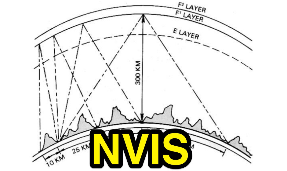 Operating NVIS mode, understanding operation frequencies, choosing the proper antenna to operate with the Near Vertical Incidence Skywave propagation
 -
 Amateur Television (ATV) operations involve transmitting and receiving live or recorded video and audio signals over amateur radio frequencies. Unlike narrow-band modes, ATV utilizes a wider bandwidth to convey video information, often requiring specialized transceivers, antennas, and signal processing equipment. This mode allows hams to share visual content, demonstrate projects, or conduct video conferences, typically on VHF, UHF, and microwave bands due to the bandwidth requirements. The SwissATV resource focuses on the technical aspects and community engagement surrounding ATV within Switzerland. It covers topics relevant to setting up ATV stations, understanding signal propagation at higher frequencies, and participating in local ATV activities. The site serves as a central point for Swiss ATV operators to exchange knowledge and coordinate transmissions, fostering the growth of this specialized amateur radio mode.
 -
 Operating a modern amateur radio station, particularly for advanced digital modes or microwave experiments, often requires precise test and measurement equipment. This resource from NI (National Instruments), now part of Emerson, showcases a wide array of hardware and software solutions designed for demanding test objectives. Their portfolio includes modular instruments and configurable software interfaces, such as _LabVIEW_ and _TestStand_, which integrate AI assistance via _NI Nigel™ AI_ for code completion and sequence building. For those involved in RF and microwave work, the offerings extend to vector signal transceivers, RF signal generators, software-defined radios, and spectrum analyzers. These tools are crucial for characterizing antenna performance, optimizing transceiver circuits, or developing custom radio systems. The company emphasizes its 50 years of innovation, with 40 years dedicated to _LabVIEW_, highlighting a long-standing commitment to engineering solutions. The site also details products for data acquisition, electronic test, and wireless design, covering components like CompactDAQ modules for precise sensor measurements and various communication bus interfaces. Their events and perspectives sections offer insights into topics such as 5G technology and strategies for breaking out of testing silos, providing a broader context for their measurement solutions.
 -
 Constructing an End-Fed Half-Wave (EFHW) antenna offers a practical solution for HF operators seeking a multiband wire antenna without the need for extensive radial systems. This design typically employs a high-impedance transformer at the feed point, matching the antenna's inherent high impedance to a 50-ohm coaxial feedline. The article specifically details a 2012 approach, focusing on a transformer with a 49:1 turns ratio, which is a common configuration for EFHW antennas. The resource outlines the construction of a wire element cut for a half-wavelength on the lowest desired band, with specific coil arrangements enabling operation on harmonically related bands such as 40m, 20m, and 10m. It discusses the physical dimensions and winding details for the matching transformer, often utilizing a ferrite toroid core to achieve the necessary impedance transformation. The content provides insights into the operational principles and practical considerations for deploying such an antenna, including methods for tuning and optimizing performance across multiple amateur radio bands. While acknowledging that the presented information from 2012 may be superseded by newer insights, it serves as a foundational reference for understanding EFHW antenna theory and construction.
 -
 Station QRP presents various **circuit diagrams** for constructing low-power AM vacuum tube shortwave transmitters, catering to enthusiasts interested in vintage radio technology. The resource details schematics ranging from simple to more complex designs, enabling hams to build their own QRP AM transmitters for operation on frequencies like 6.925 kHz AM. It emphasizes the use of vacuum tubes, providing a technical foundation for understanding and replicating classic shortwave broadcasting methods. The content is geared towards those who enjoy the hands-on aspect of electronics and the unique characteristics of tube-based RF circuits. Building these transmitters allows operators to experience the nostalgia of early shortwave radio, with the site specifically mentioning a pioneer station on 6.925 kHz AM. The designs facilitate experimentation with low-power AM transmission, offering practical application for homebrew projects. The focus on QRP (low power) operation aligns with a segment of the amateur radio community that values efficiency and minimalist setups, providing a distinct alternative to modern solid-state transceivers.
 -
 Voldatech, a manufacturer based in China, produces a range of RF feeder cables and site components essential for amateur radio installations and telecommunication infrastructure. Their product line includes various types of coaxial cables, such as **50 Ohm** and 75 Ohm options, along with a comprehensive selection of connectors like N-type, UHF, and BNC. These components are critical for maintaining signal integrity and minimizing loss in antenna systems, whether for a home shack or a remote DXpedition setup. The company's focus on _RF Coax cables_ and connectors directly supports the needs of radio amateurs seeking reliable transmission lines for their transceivers and antennas. Amateurs often compare Voldatech's offerings to established brands, evaluating factors such as impedance matching, shielding effectiveness, and durability under various environmental conditions. The availability of diverse cable types allows operators to select optimal solutions for different frequency bands and power levels, from QRP to high-power amplifier setups. Their products are particularly relevant for those constructing new antenna arrays or upgrading existing feedline systems, aiming to achieve maximum power transfer and reduce standing wave ratio (SWR) for efficient signal propagation.
 -
 The Terminated End Fed Vee Antenna (TEFV) is a travelling wave antenna with constant current distribution. Unlike traditional resonant antennas, TEFV operates without standing waves, using a terminating resistor for broadband efficiency. With a combination of vertical and horizontal polarization, it offers wide bandwidth from 1.8 MHz to 30 MHz, eliminating the need for a tuner. Key components include a 9:1 unun transformer and a 500-ohm terminating resistor. Grounding and counterpoise enhance performance, and it can handle power losses of up to 30%. TEFV provides an effective, versatile antenna solution for amateur radio and broadcast applications.
 -
 Undestanding and measuring SWR, Standing Wave Ratio in antenna feed lines. This article also introduce basic concepts and usage guidelines of amateur radio antenna tuners
 -
 Microwaves101 provides an extensive repository of information covering fundamental principles of microwave design, targeting engineers and radio amateurs interested in the higher frequency spectrum. The site features a detailed _encyclopedia_ of microwave terms and concepts, alongside practical design considerations for various components and systems. It serves as a foundational reference for understanding RF propagation, transmission lines, and active/passive microwave circuits. The resource includes numerous calculators for impedance matching, filter design, and other critical RF parameters, facilitating hands-on project development. Discussions on **10 GHz** equipment and **24 GHz** projects highlight practical amateur radio applications, extending to operations up to 134 GHz. Content spans from basic theory to advanced topics like MMIC design and antenna characteristics, supporting both educational and practical endeavors in microwave technology.
 -
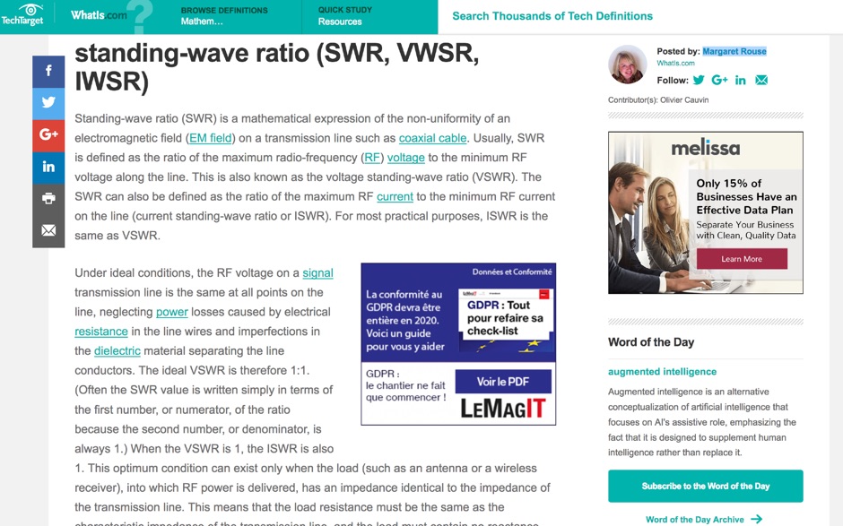 Article about Standing-wave ratio (SWR) defined as a mathematical expression of the non-uniformity of an electromagnetic field on a transmission line. SWR is the ratio of the maximum radio-frequency (RF) voltage to the minimum RF voltage along the line.
 -
 The video showcases the setup of a 300 MHz oscillator, a 100W radiofrequency amplifier, and a dipole antenna for transmitting radio waves, leading to the fluorescence of a nearby light bulb. It demonstrates the presence of standing waves on the dipole antenna and how intensity varies along its length. Additionally, the usage of a copper pipe as a receiving antenna is explored, showing changes in intensity depending on alignment and proximity to the transmitter. Finally, a B field antenna sensitive to magnetic fields is introduced, revealing brightness variations in different orientations. The video offers insightful observations on radio wave transmission and reception phenomena.
 -
 When building antennas for the Wifi band (Like the 8dBi omni), a need for an easy way to check the antennas arose. A Voltage Standing Wave Ratio (VSWR) meter useable at the 2.4GHz band is however, hard to find.
 -
 This page provides guidance on designing an End-Fed Half-Wave (EFHW) or Random-Length antenna for amateur HF bands, such as 80 or 40 meters. The content explains how to optimize the antenna for multi-band use and match it to a 50-ohm system using an unun. Hams can generate radiation patterns, VSWR charts, and antenna current diagrams for their customized antenna designs. Understanding how antenna dimensions affect performance is essential for successful field operations. The page caters to ham radio operators looking to build efficient and effective HF antennas for their stations.
 -
 This page delves into the debate surrounding the End-Fed Half-Wave (EFHW) antenna, exploring whether it is truly a multiband antenna without the need for a tuner. The author investigates the claims and criticisms surrounding these popular antennas, discussing their resonance on various bands and their efficiency for DXCC achievements. The content is valuable for hams interested in understanding the capabilities of EFHW antennas and their performance across different HF bands, with a focus on practical usage and real-world results.
 -
 This article focus on the radiation angle of vertical antennas and the fundamentals of electromagnetic wave propagation. The calculation of antenna length at 145 MHz is followed by an explanation of electromagnetic wave speed and the link between wavelength, frequency, and velocity. Author discusses the 5/8th wave vertical antenna, namely its performance and the influence of radiation angle on signal transmission. Figures and analogies demonstrate how different antenna types produce distinct radiation patterns. This highlights the importance of selecting the right antenna for a certain purpose, such as local traffic or dxing. The article discusses a variety of factors that affect antenna performance, including SWR, propagation conditions, and equipment dependability
 -
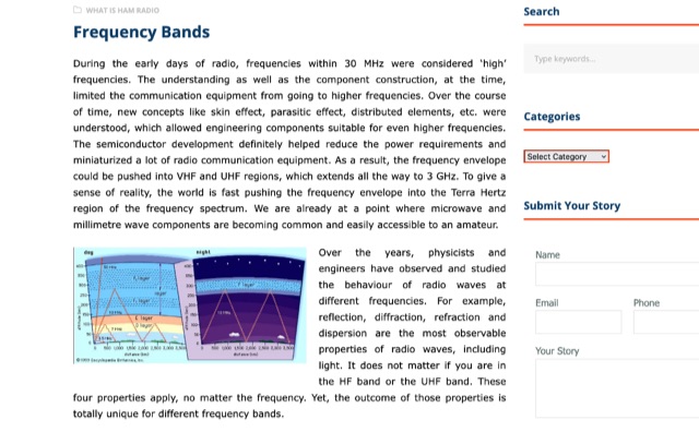 During radio's early days, high frequencies were under 30 MHz due to technical limitations. As understanding grew, components improved, allowing for higher frequencies like VHF and UHF up to 3 GHz. The HF band's long wavelengths provide unique propagation challenges influenced by solar activity. VHF and UHF bands face diffraction and reflection issues but offer diverse applications, from amateur radio to 5G and GPS technologies.
 -
 This PDF file provides detailed information on HF propagation for ham radio operators. It covers the principles of how radio signals travel over long distances, including factors that affect signal strength and propagation. The content is useful for hams looking to improve their understanding of radio communication and optimize their transmissions. Whether you're a beginner or an experienced operator, this resource offers valuable insights into HF propagation that can enhance your communication skills and efficiency on the airwaves.
 -
 The article explores the concepts of return loss, VSWR, and S11 within the context of microwave engineering, highlighting the confusion arising from their definitions. It clarifies that these parameters, while seemingly distinct, fundamentally describe the same phenomenon related to wave reflection and transmission in microwave circuits. The discussion emphasizes the historical context and mathematical relationships among these terms, revealing that their interpretation can vary significantly across different engineering disciplines. Ultimately, it advocates for a pragmatic approach to using these parameters based on familiarity rather than strict definitions.