Search results
Query: t match 2m
Links: 25 | Categories: 0
-
 The G5RV antenna, with an overall length of **31.10m (102ft)**, functions as a 3/2-wave on 20 meters when installed horizontally at 12m (39ft), exhibiting a resonant frequency of 14.150MHz and an approximate resistance of 80 ohms. Its 10.36m (34ft) stub line, designed as a 1/2-wave on 14.150MHz with a 0.97 velocity coefficient, acts as an impedance transformer across other bands, aiming for multiband operation without traps. On 20m and higher frequencies, the G5RV demonstrates improved gain compared to a standard dipole, attributed to the _collinear effect_ from multiple 1/2-waves along the wire. The original design sought a multiband solution for limited spaces, often requiring an Antenna Tuning Unit (ATU) for effective operation across bands like 80, 40, 30, and 20m, particularly with modern solid-state PAs. Variants, such as the F8CI modification, incorporate a 1/4 current balun at the stub line's base for symmetrical-to-asymmetrical transition, known as a _remote balun_. Proper flat-top or inverted-V installation is critical for maintaining symmetry and collinear gain, with inverted-V apex angles below 120° progressively diminishing higher-band performance.
 -
 Details the construction of a **multiband vertical** antenna, specifically designed for stealth operation in a rented property, covering 80m, 60m, 40m, and 30m. The author, N3OX, leverages a 12m Spiderbeam telescoping fiberglass pole as the primary support, noting its sturdiness compared to typical fishing rods while remaining light enough for quick deployment and takedown. The radiating element is a 14 gauge Flex-Weave wire, attached to the pole's top with a rubber grommet, and fed by 27 bare 18 gauge radials spread across a 40-foot square backyard. N3OX describes the impedance matching solution, opting for custom-built L-networks over a remote tuner to enable fast bandswitching. Using an MFJ-259B and EZNEC modeling, base impedances were measured and component values calculated with G4FGQ's L_TUNER and SOLNOID_3 programs. The 80m coil is wound on a 3.5-inch PVC form, while the 30m, 40m, and 60m coils are air-wound, self-supporting #10 wire. Variable capacitors are incorporated for 40m and 30m shunt elements, with the 60m impedance matched by a series inductor. The project includes a **servo-controlled** homebrew band switch, utilizing a two-pole 12-position ceramic wafer switch for remote operation, addressing the limited 80m bandwidth. The entire matching network is housed in a weather-resistant shelter constructed from lumber and aluminum flashing. N3OX reports good DX results at 100W, estimating the total cost between $150 and $250, depending on existing parts.
 -
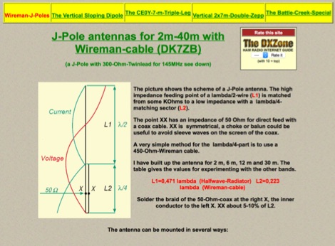 J-Poles with Wireman-cables for the quarterwave matching section, working on VHF and HF bands
 -
 Yagis for homemade with a new match-system, for 6m, 4m, 2m, 70cm and Shortwave
 -
 Demonstrates the construction and performance of an updated ZS6BKW multiband dipole, a variant of the _G5RV_ antenna, specifically designed for HF operation. The article details a real-world installation using 13.5m copper wire elements and 12.2m of 450 Ohm ladder line, configured as a sloping inverted-V with the apex at 10m and ends at 4m above ground. It covers the critical aspect of impedance matching, incorporating an 8-turn choke balun at the feedline transition to RG-58U coax to mitigate RF common mode current. Measurements confirm favorable SWR readings below **1.3:1** on 7.1 MHz, 14.11 MHz, 18.06 MHz, and 24.8 MHz, indicating effective resonance across 40m, 20m, 17m, and 12m bands. The installation also shows usable SWR dips on 3.55 MHz (5:1), 29.02 MHz (2:1), and 50.84 MHz (3:1), extending its utility to 80m, 10m, and 6m with an antenna tuning unit. Initial on-air results report clear reception of stations over **5000km** away, validating its DX potential.
 -
 50MHz-Yagis with a new match, all lengths from 0.6-12m
 -
 PA0FRI's "S-MATCH ATU" published in RSGB's RadCom March 2003). The Balanced Universal ATU Photographs of ZL2ML's S-Match were added.
 -
 F6EZX presents a detailed account of constructing a compact, multi-band _Levy antenna_ for portable holiday operations, specifically addressing issues with local QRM from a previous _Deltaloop_ setup. The article outlines the design criteria, including multi-band operation on 40m, 30m, 17m, 15m, 12m, and 10m, a symmetrical configuration to reduce interference, and a low take-off angle for DX. Construction involves 2x 10.3m radiating elements and a 15.3m open-wire feeder (ladder line) with 7cm spacing, made from 1.5mm2 copper wire and foam pipe insulation spacers. Theoretical calculations, referencing F9HJ's "_Les antennes Levy_" book, guide the determination of element lengths and feeder impedance characteristics, aiming for a good match across bands with a commercial antenna tuner. Initial field tests with the _VCI Vectronics VC300DLP_ tuner showed a 1:1 SWR from 80m to 10m, with some difficulty on 17m. The antenna, mounted as a 45-degree slopper with the high point at 12m, successfully facilitated DX contacts to South America, particularly Chile and Argentina, suggesting a lower take-off angle compared to the previous Deltaloop which favored Brazil. The Levy antenna significantly reduced TVI/RFI, attributed to its improved symmetry and greater distance from the QRA. While signal reports on 15m and 20m were 1-2 S-points lower than the Deltaloop, its performance on 40m and 30m was comparable, fulfilling the design goals for a portable, low-cost, multi-band solution.
 -
 Constructing an HF End-Fed Half-Wave (EFHW) vertical antenna, the resource details the winding of a monoband matching unit, inspired by _AA5TB_, designed to provide a 50 Ohm impedance match without a ground plane or antenna tuner. It specifies the use of a _T200-2_ ferrite core for the transformer, outlining the 13-turn secondary and 2-turn primary winding process with enamelled copper wire. The document also describes the integration of a coax capacitor, whose length is critical for tuning and varies by band, with specific starting lengths provided for 20m, 17m, 15m, 12m, and 10m operation. The practical application section guides the builder through tuning the antenna using an antenna analyzer, emphasizing the iterative process of spacing secondary windings and trimming the coax capacitor to achieve resonance at the desired band frequency. It highlights the antenna's low angle of radiation, beneficial for DX, and claims up to 2 S-points improvement over a _G5RV_ or similar doublet when used as an omnidirectional vertical. A comprehensive shopping list, including specific part numbers from _Rapid Electronics_, is provided, along with advice on selecting fiberglass fishing poles for support and suitable antenna wire.
 -
 The ZS6BKW wire antenna, a variant of the G5RV, utilizes a specific 13m (42.6 ft) length of 450-ohm window line as its matching section, feeding a 28.5m (93.5 ft) flat-top element. This design aims for lower SWR on 40m, 20m, 17m, 12m, and 10m compared to a standard G5RV, often achieving SWR values below 1.5:1 on these bands without an antenna tuner. The feedpoint impedance transformation provided by the window line allows for direct connection to 50-ohm coax on multiple bands. F4FHH's experience involved constructing the ZS6BKW and evaluating its performance against an _OCF dipole_ (Off-Center Fed) on various HF frequencies. The article includes observations on SWR readings and operational effectiveness, highlighting the ZS6BKW's suitability for multi-band operation. The antenna's overall length, including the flat-top and window line, is approximately **41.5 meters** (136 feet), making it a significant wire antenna for fixed station use. Comparative analysis with the OCF dipole provided practical insights into the ZS6BKW's advantages and limitations, particularly concerning bandwidth and tuner requirements.
 -
 An interesting article on building a 4 elements yagi antenna with gamma match for the 2 meter band. This article include two videos demonstrating assembling procedure by KG0ZZ
 -
 A Half wave antenna has a high impedance feed point. This can be matched using a 1/4 wave stub matching section and converts the 40m vertical into an L-shaped 20m J-Pole antenna. The 300 ohm feeder used for this purpose must be kept away from the ground.
 -
 High gain, good pattern and acceptable bandwidth. These aims can be realized with a radiation-resistance of 25-35Ohms, because the 28-Ohm-feedpoint is very simple to match.
 -
 Demonstrates the design and construction of a compact, portable multi-band mini-delta loop antenna, specifically optimized for /P (portable) operations from remote locations like Scottish islands. The resource covers the theoretical underpinnings of half-wave loops, contrasting closed and open configurations, and then details the application of a folded dipole principle to achieve a 50-ohm match for direct coax feed. It presents empirical formulas for calculating element lengths, considering the velocity factor of common wire types, and provides a detailed example for a 20m (14.175 MHz) version. The article includes a comprehensive table of dimensions and allowances for a five-band (20m, 17m, 15m, 12m, 10m) mini-delta beam, along with construction hints for the central support and balun. It specifies a 1:1 trifilar balun wound on a ferrite rod and describes the antenna adjustment process using an _MFJ-259B Antenna Analyser_. Initial test results indicate an SWR of 1:1 at resonance and a bandwidth of approximately 240 kHz on 20m, even at a low height of five feet above ground. The distinctive utility lies in its focus on a practical, easily deployable beam antenna for portable DXing, offering a viable alternative to more complex or larger arrays.
 -
 GW4ALG's _136 kHz Pages_ document the evolution of vertical antennas for the 2200m band, starting with a prototype mounted on a house wall. This initial design, despite achieving the first **395 km** GM-GW QSO, suffered from significant insulation breakdown, high RF losses due to proximity to the house, and difficult tuning adjustments. The author details the challenges of maintaining resonance and matching with a variometer in the loft, noting that adding three earth spikes offered no measurable improvement over a simple water tap connection. The subsequent experimental 12m vertical, relocated away from the house, significantly reduced dielectric losses and proved far more effective. This antenna enabled GW4ALG to set a world DX record on 136 kHz with a **1916 km** QSO to OH1TN, and an intra-UK record of **703 km** to GM3YXM/P. The resource further explores the use of helium-filled balloons to extend the vertical radiator, achieving heights up to 27m, typically 20m, for enhanced low-band performance. Practical advice on balloon types, inflation, and critical insulation between the wire and balloon is provided, emphasizing safety and avoiding arcing.
 -
 Demonstrates the construction of a 144 MHz turnstile antenna, detailing its design for omnidirectional, horizontally polarized VHF operation. The resource outlines the physical dimensions and materials required, including specific lengths for the radiating elements and the use of _RG-58_ coaxial cable for phasing. It covers the assembly process, emphasizing the critical spacing and connection points to achieve the desired radiation pattern and impedance matching for the _2-meter band_. The article presents measured _SWR_ performance across the 144-146 MHz segment, showing a low SWR of 1.2:1 at 144.5 MHz, which is suitable for general VHF use. It compares the turnstile's performance to a 9-element Yagi, noting the turnstile's advantage in providing consistent signal strength from all directions without requiring a rotator. Practical application for local FM simplex and repeater operations is implied, offering a simple yet effective antenna solution for fixed or portable stations.
 -
 Demonstrates the adaptation and construction of a 7-element DK7ZB Yagi antenna for the 4-meter band (70 MHz), utilizing components from a defunct 2-meter CUE DEE Yagi. The resource details the modifications made to the original DK7ZB design to fit the shorter CUE DEE boom length, specifically adjusting element lengths for 6mm rod elements while reusing existing mounting holes for the reflector and last director. It provides precise element lengths for the reflector, dipole (12mm aluminum tube), and five directors, along with a note on cutting elements for transport. The article includes a 4NEC2 simulation file for performance analysis and an SWR plot, confirming the antenna's electrical characteristics. It also specifies the calculation for the quarter-wavelength matching cable using SAT752F coaxial cable, resulting in a 909mm length. Practical application is shown with the finished antenna in operation at JO20XC, listing several activated Maidenhead squares such as JO56PA and JP40KS, validating its effectiveness for portable 70 MHz operations.
 -
 Presents the construction of a 2-meter **Skeleton Slot Yagi** stack, detailing the design process and practical considerations for VHF operation. The author shares insights from building and testing this antenna, emphasizing its performance characteristics for local and extended range contacts. The project outlines the specific dimensions and materials used, providing a clear path for other radio amateurs to replicate or adapt the design for their own stations. The resource covers the unique aspects of the Skeleton Slot radiator, explaining how its geometry contributes to gain and pattern control. It includes discussions on impedance matching and feedline considerations crucial for optimizing power transfer and minimizing SWR. The article draws on real-world testing, offering practical results that validate the theoretical design. This project serves as a valuable reference for those interested in custom VHF antenna solutions.
 -
 HB9BZA's LoTW users list, originally compiled since 2005 from DX-Cluster and user submissions, now primarily leverages the official ARRL full users list released on July 29th, 2017. This resource details 228,012 calls across 340 current DXCC entities, with the latest update noted on March 2, 2026. It offers various formats, including a full list, text versions, and breakdowns by country, providing valuable insights into LoTW participation for DXers. While the ARRL's official list with "last upload" dates diminished the original list's unique utility, HB9BZA's site continues to offer statistics and user counts by country, which remain of interest. The author, HB9BZA, expresses gratitude to contributors who helped maintain the list's accuracy over many years, achieving an impressive 96.4% match with the ARRL's data before the official release. Knowing which stations are LoTW active encourages more hams to join the system, demonstrating that even rare DXCC entities like Ducie Island or Heard Island can be confirmed quickly. For instance, HB9BZA recounts a 36-minute QSL confirmation for a 3A2MW contact. The list also integrates with the RXCLUS packet radio/telnet client, enhancing DXCC award tracking by identifying LoTW participants and utilizing upload dates for alarms.
 -
 The **136kHz Vertical Antenna** at G3YMC employs a Butternut HF2V structure, standing 10m tall. It integrates a 6.5mH loading coil to achieve resonance, with a matching transformer for impedance adjustment. The antenna's configuration includes top loading via a 12m horizontal wire, enhancing capacitive impedance. Initial measurements indicated a high impedance of around 300 ohms, necessitating a transformer for a 50-ohm match. Despite challenges with ground losses, the vertical antenna has shown improved performance in specific directions, filling nulls present in the previous loop antenna setup. The tuning remains broad, with variations due to environmental factors affecting the matching. Ongoing adjustments and comparisons with the loop antenna will continue to refine its effectiveness.
 -
 Construction of an antenna for experimental satellite communication, 8el. (435 Mhz) x 4el. (145 Mhz) Satellite Yagi crossed. No difficulty to built this antenna. Except the gamma match. that requires a little more attention
 -
 Paul McMahon presents a compact VSWR meter designed for QRP portable use, ideal for SOTA operations with rigs like the FT817. The device, constructed from readily available components, employs a simple resistive bridge for wideband performance from 1.8MHz to 52MHz, with diminishing accuracy at higher frequencies. Key features include no need for external power, simple calibration, and operation with low power levels. The design, detailed with parts lists, schematics, and construction guidelines, ensures a 2:1 worst-case VSWR to protect transceivers during antenna matching. Calibration points are set for accurate VSWR readings at various loads.
 -
 This project details the design and construction of a Spider Quad antenna for HF bands (20m, 17m, 15m, 12m, and 10m). The boomless structure optimizes driver and reflector spacing, enhancing performance. Tuning and impedance matching were refined using antenna analyzers and a 1:2 balun. Final tests confirmed excellent SWR and gain, making this an efficient solution for top performance DXing.
 -
 The 2m 7 element Yagi antenna is a perfect beam antenna with 11dB gain and a front-to-back ratio of 20-25 dB. It has seven elements and requires a matching network built of 3/8" aluminum tubing and RG-8 cable. The gamma tube is adjusted to provide the best fit, and the gamma-driven element feeding clamp is tightened. If the beam is vertical, a non-conducting mast is utilized to prevent detuning and skewing of the radiation pattern. For optimal VHF operating, the antenna is installed at a height of 30 feet or higher.
 -
 145 MHz is the target frequency for this 2-meter Skeleton Slot Yagi Stack antenna project. The design focuses on feeding two stacked Yagi antennas using a skeleton slot radiator, which is a unique approach for VHF enthusiasts. The project details the construction process, including the loop tapered matching section for impedance matching, ensuring optimal performance. The use of specific components like the EH789 element holder and MB456 main mast bracket is highlighted, providing clarity on the assembly process. The construction utilizes 20x20 box aluminum bar for durability and precision. Key dimensions, such as the element length (ER-ED4) and main boom spacing (MM123), are meticulously outlined. This attention to detail aids in replicating the antenna design accurately. The downloadable PDF offers comprehensive instructions, making it accessible for amateur radio operators interested in VHF antenna construction. This project is particularly beneficial for those looking to optimize their 2-meter band operations. The inclusion of a skeleton slot radiator and loop tapered matching section demonstrates advanced techniques in antenna design, catering to both intermediate and advanced builders.