Search results
Query: tri wire
Links: 114 | Categories: 0
-
 Demonstrates the construction of a **multi-band HF mobile antenna** utilizing a modified CB whip antenna base. The resource details the process of stripping a commercial CB whip, winding a new helical coil with 0.7mm insulated copper wire, and identifying tapping points for various HF bands. It emphasizes the importance of a rugged, slim design for mobile operation, discussing mechanical length, power handling (up to 200 watts), and coil diameter considerations. The article includes a graphic illustrating the antenna's operational principle, where sections of the helical coil are shorted from bottom to top to maintain efficiency and high Q. The resource presents a practical approach to achieving **band switching** without an external tuner, by manually adjusting tapping points on the coil. It provides a table with reference lengths in centimeters from the feedpoint for 7 MHz (40m) through 28.7 MHz (10m), including WARC bands. The author details mounting techniques, suggesting a Diamond bracket for secure attachment to a vehicle trunk, and stresses the critical role of proper grounding for optimal performance. The design allows for operation on 75m and 80m bands by adding a 110mm steel whip.
 -
 The G5RV antenna, with an overall length of **31.10m (102ft)**, functions as a 3/2-wave on 20 meters when installed horizontally at 12m (39ft), exhibiting a resonant frequency of 14.150MHz and an approximate resistance of 80 ohms. Its 10.36m (34ft) stub line, designed as a 1/2-wave on 14.150MHz with a 0.97 velocity coefficient, acts as an impedance transformer across other bands, aiming for multiband operation without traps. On 20m and higher frequencies, the G5RV demonstrates improved gain compared to a standard dipole, attributed to the _collinear effect_ from multiple 1/2-waves along the wire. The original design sought a multiband solution for limited spaces, often requiring an Antenna Tuning Unit (ATU) for effective operation across bands like 80, 40, 30, and 20m, particularly with modern solid-state PAs. Variants, such as the F8CI modification, incorporate a 1/4 current balun at the stub line's base for symmetrical-to-asymmetrical transition, known as a _remote balun_. Proper flat-top or inverted-V installation is critical for maintaining symmetry and collinear gain, with inverted-V apex angles below 120° progressively diminishing higher-band performance.
 -
 This guide provides step-by-step instructions for constructing a tin can waveguide antenna, commonly known as a cantenna, for enhancing WiFi signal range. The project is budget-friendly, costing under $5, and utilizes easily accessible materials like a food can and basic electronic components. The design is suitable for 802.11b and 802.11g wireless networks, operating within the 2.4 GHz frequency range. To start, gather the necessary parts including an N-Female chassis mount connector, nuts, bolts, and a suitable can. The assembly process involves drilling holes in the can for the connector and mounting the probe. The guide emphasizes the importance of can dimensions and placement for optimal performance, encouraging experimentation for best results. This project is ideal for amateur radio operators and DIY enthusiasts looking to improve their wireless connectivity without significant investment. Safety precautions are advised, as the author does not hold electrical engineering credentials. Users are encouraged to take responsibility for their equipment and ensure proper assembly. With this simple yet effective antenna, users can extend their WiFi coverage and enjoy enhanced connectivity.
 -
 An effective 10-20m DX antenna for deed restricted lots. The article by K7ZB introduces a simple 10-20m DX antenna suitable for deed-restricted lots. The antenna, a 15' vertical design, facilitated contacts with over 200 countries worldwide. Its design employs a telescopic aluminum tube and radial wires for multi-band operation, requiring an external antenna tuner for optimal performance. The mounting scheme and construction details ensure effectiveness and ease of use.
 -
 This resource details the fundamental aspects of deploying longwire antennas, emphasizing ease of construction and installation for shortwave listening (SWL) and broadcast reception. It covers wire gauge selection, suggesting 14 to 24 AWG for general use, with heavier gauges (14-20 AWG) for permanent outdoor installations. Guidance is provided for various deployment scenarios, including indoor setups where the wire can be run around a room, temporary outdoor installations from balconies using light 18-24 AWG wire, and permanent outdoor configurations requiring higher placement and slack for tree movement. Feeding methods are discussed, recommending coaxial cable (50-75 ohms) to mitigate man-made interference, with instructions for connecting only the center conductor to the longwire. Safety precautions are highlighted, particularly avoiding contact with power lines and conductive materials, and managing static electricity buildup by unplugging the antenna after use and bleeding off charges before connection. The article also advises against using outdoor longwires during thunderstorms or snowstorms due to static and lightning risks. Optimal height considerations are presented, advocating for the highest safe placement, ideally a couple of feet above underlying structures, to maintain free air space. The text mentions a personal setup with one end at a roof peak (20 feet) and the other at a 17-foot mast, illustrating practical deployment without strict height requirements beyond safety and clearance.
 -
 The page provides a project for an indoor wire antenna for the 7 MHz band, based on a design by F6CYV. It aims to help amateur radio operators lacking space to set up an antenna for 40 meters. The author shares their experience using the antenna inside an apartment, noting good reception of European signals and contacts with over 150 countries. The project details the materials and dimensions needed for the antenna, along with tips for optimal performance.
 -
 Presents the official online presence for Yaesu, a prominent manufacturer of radio communication equipment. The site details their extensive product lines, encompassing amateur radio transceivers, antenna rotators, tuners, amplifiers, and various accessories like microphones, speakers, and power supplies. It functions as a central hub for product information, specifications, and support resources. The resource categorizes its offerings across several key areas, including **Digital Mobile Radio (DMR)** solutions, HF/VHF/UHF transceivers, and specialized receivers and scanners. Each product section typically includes model numbers, feature highlights, and often links to manuals or technical documentation, providing hams with essential data for equipment selection and operation. Beyond amateur radio, the site also covers Yaesu's contributions to aviation and marine radio sectors, illustrating the company's broader scope in wireless communication technology. It serves as a direct portal for accessing manufacturer-provided details, ensuring accuracy and currency for those researching Yaesu gear.
 -
 This PDF article from April 2001 QST details the construction of the "NJQRP Squirt," a reduced-size 80-meter inverted-V dipole antenna. The resource provides a general construction sketch, a photograph of the assembled antenna, and specific dimensions for PC-board insulators. The antenna consists of two wire legs, each approximately **34 feet long**, separated by 90 degrees, fed at the center. It is designed for operation on 80 meters (3.5-4.0 MHz) as a quarter-wavelength antenna, requiring a low-loss feedline and an external antenna tuner due to its non-resonant feedpoint impedance. Construction utilizes readily available materials, including 1/16-inch glass-epoxy PC board for end and center insulators, and #20 or #22 insulated hookup wire for the elements. The feedline specified is 300-ohm TV flat ribbon line, with a note on potential trimming for tuner compatibility. N2CX reports the antenna's center should be elevated to at least **20 feet**, with ends no lower than seven feet above ground, resulting in a ground footprint of approximately 50 feet wide. The design prioritizes NVIS propagation for local 80-meter contacts. DXZone Focus: PDF Article | 80m Inverted-V Dipole | Construction Notes | 34 ft element length
 -
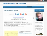 Pictures of a multiband dipole, build with simple PVC T and standard electrical wire
 -
 High Performance Lightweight Antennas. The spider beam is a full size lightweight tribander yagi for 20/15/10m, made from fiberglass and wire. It has been specially developed as a highly efficient antenna for dx-pedition and portable use.
 -
 Do these things do exactly what they say they do, or are they total hogwash? - Patrick lifts the lid on the MLB
 -
 Types of beverage wires, choose best supports and insulators, multiple antennas at one feedpoint, all well documented with photos and exaustive explanation. This article offers insights on building Beverage antennas for optimal reception. Key takeaways include using strong wire (copperweld or electric fence), proper termination, and a good grounding system (multiple copper rods). The author recommends maximizing antenna length and orienting it towards desired stations. For best results, utilize an antenna tuner and experiment with termination resistors.
 -
 HF Wire Yagi antenna with notes and eznec file on original article of a Portable 3-Band Yagi antenna for 10-15-20 meter band made with wire elements. Include link the original to QST article.
 -
 Presents the KE4UYP linear-loaded vertical antenna design, which introduces very little loss on 80 or 160 meters, achieving an overall radiation efficiency of 80% to 85%. This design addresses common pitfalls of traditional base-fed verticals by placing the majority of the current at the top of the antenna, eliminating the heavy reliance on extensive ground radial systems. The author's initial 10-meter model, only three feet tall, yielded 5/9 signal reports to Anchorage, AK, and Europe, confirming its effectiveness. The antenna incorporates both vertically and horizontally polarized radiators, with a 1/4 wavelength horizontal counterpoise located at the feed-point, near the top, to create an almost totally omnidirectional pattern with high wave angle horizontally polarized radiation. This dual polarization ensures even illumination across all take-off angles, making it effective for both local contacts and **DXing**. The vertical element is linear loaded, adding capacitance reactance and making it longer than the horizontal element to achieve resonance and raise the feed-point impedance to 50 ohms. Fine-tuning the antenna requires careful adjustment, as tower reactance can vary. The article suggests starting with 80 feet for 80m and 170 feet for 160m for the vertical wire, then trimming for resonance. Bandwidth specifications include 300 kHz under 2:1 **SWR** on 80m and 100 kHz on 160m when suspended between trees, or 150 kHz on 80m when side-mounted on a tower.
 -
 The Flower Pot Antenna project details a portable dual-band antenna primarily operating on 10 meters, with secondary resonance near the 30-meter band. Construction involves winding RG58 coaxial cable uniformly around a large plastic flower pot, approximately 70cm high with a 60cm top diameter. The design eliminates the need for radials, contributing to its compact and lightweight nature. Key construction steps include soldering the inner conductor to the shield at one end of the wound cable and connecting the wound cable's shield to the rig cable's inner conductor at the base. An LC network, comprising a variable capacitor (0-200pF) and an inductor (10 coils, 5cm diameter, 2mm wire), is inserted between the wound cable's inner conductor and the rig cable's shield. Tuning is performed with an antenna analyzer, adjusting cable length and the variable capacitor for optimal impedance on 10 meters. The antenna performs effectively when installed horizontally.
 -
 Demonstrates the construction and on-air performance of the _NB6Zep_ antenna, a modified 20-meter Extended Double Zepp design optimized for multi-band operation from 40 through 10 meters. The resource covers basic design principles, including dimensions of 66 feet horizontal and 5 feet vertical elements, and specifies open ladder line or TV twin lead for the transmission line. It details material selection for low-cost wire antenna construction, such as 18 AWG wire for the legs and ceramic or plastic insulators, along with practical tips for soldering connections and insulating against moisture. The author, NB6Z, shares insights from extensive _EZNEC_ modeling to optimize the antenna's total length for a 40-meter half-wave dipole footprint and feed line length for direct tuner connection. The article presents field results, including successful _PSK31_ contacts from Oregon to the East Coast on 40 and 30 meters with 50 watts, even at a low height of 6 feet. It provides detailed performance characteristics for each band, noting the _NB6Zep_'s highest gain (over 3 dB) and sharp, medium-angle lobes on 20 meters, which yielded strong DX reports to locations like Korea, Japan, and Argentina. For 17 and 15 meters, it describes a butterfly-like pattern with broad lobes, while 12 and 10 meters exhibit narrow, directional lobes in an "X" configuration. The author also shares personal experiences operating successfully for over a decade in an antenna-restricted environment using the NB6Zep and other stealth wire antennas.
 -
 manufactures and distributes HF, VHF, UHF and SHF equipment covering 10MHz. - 47.0GHz. Our products include: Wireless LAN / WAN Bidirectional Linear Amplifiers, Low Noise Preamplifiers - LNA's, RF Linear Amplifiers, Relays, Transverter Systems, Frequency Translation Systems, Downconverters, Antennas, Parabolic Dishes, Coaxial Cable, Relays, Antenna Switches, Microwave Test equipment, PC controlled Receivers, Microwave Linear Amplifiers including models for Telemetry, Wireless, and CDMA applications.
 -
 A Portable 2 element Triband Yagi antenna that can work on 10 15 20 meter band by VE7CA
 -
 AEA Technology Inc. is a pioneer and leading manufacturer of RF and cable test equipment for the wireless, Telco, CATV, NMR & MRI, RFID, telemetry, aviation, commercial, military, and two-way radio industries. Produces SWR Meters, Pre Amplifiers, filters, power meters and antenna testing products
 -
 F6EZX presents a detailed account of constructing a compact, multi-band _Levy antenna_ for portable holiday operations, specifically addressing issues with local QRM from a previous _Deltaloop_ setup. The article outlines the design criteria, including multi-band operation on 40m, 30m, 17m, 15m, 12m, and 10m, a symmetrical configuration to reduce interference, and a low take-off angle for DX. Construction involves 2x 10.3m radiating elements and a 15.3m open-wire feeder (ladder line) with 7cm spacing, made from 1.5mm2 copper wire and foam pipe insulation spacers. Theoretical calculations, referencing F9HJ's "_Les antennes Levy_" book, guide the determination of element lengths and feeder impedance characteristics, aiming for a good match across bands with a commercial antenna tuner. Initial field tests with the _VCI Vectronics VC300DLP_ tuner showed a 1:1 SWR from 80m to 10m, with some difficulty on 17m. The antenna, mounted as a 45-degree slopper with the high point at 12m, successfully facilitated DX contacts to South America, particularly Chile and Argentina, suggesting a lower take-off angle compared to the previous Deltaloop which favored Brazil. The Levy antenna significantly reduced TVI/RFI, attributed to its improved symmetry and greater distance from the QRA. While signal reports on 15m and 20m were 1-2 S-points lower than the Deltaloop, its performance on 40m and 30m was comparable, fulfilling the design goals for a portable, low-cost, multi-band solution.
 -
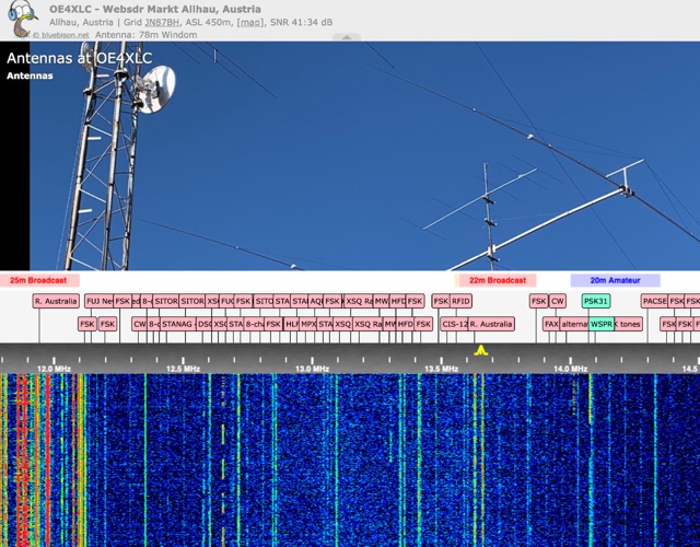 OE4RLC, OE3DUS in Allhau Austria with wire antenna and full HF amateur radio bands coverage
 -
 Constructing an HF End-Fed Half-Wave (EFHW) vertical antenna, the resource details the winding of a monoband matching unit, inspired by _AA5TB_, designed to provide a 50 Ohm impedance match without a ground plane or antenna tuner. It specifies the use of a _T200-2_ ferrite core for the transformer, outlining the 13-turn secondary and 2-turn primary winding process with enamelled copper wire. The document also describes the integration of a coax capacitor, whose length is critical for tuning and varies by band, with specific starting lengths provided for 20m, 17m, 15m, 12m, and 10m operation. The practical application section guides the builder through tuning the antenna using an antenna analyzer, emphasizing the iterative process of spacing secondary windings and trimming the coax capacitor to achieve resonance at the desired band frequency. It highlights the antenna's low angle of radiation, beneficial for DX, and claims up to 2 S-points improvement over a _G5RV_ or similar doublet when used as an omnidirectional vertical. A comprehensive shopping list, including specific part numbers from _Rapid Electronics_, is provided, along with advice on selecting fiberglass fishing poles for support and suitable antenna wire.
 -
 One of the most important considerations when designing and building a Yagi antenna is the method used to attach the elements to a boom. This is true because the boom influences the electrical length of the elements. In this article JH Reisert explain with drawings techniques on mounting yagi antenna elements to a boom
 -
 End-Fed Half-Wave Antennas (EFHWAs) are analyzed for their utility in portable QRP operations, emphasizing their simplicity, efficiency, and predictable radiation patterns compared to other portable antenna types. The discussion contrasts EFHWAs with vertical antennas, random length wires, and center-fed dipoles, highlighting the common pitfalls of each, such as ground system dependency for verticals and feedline issues for dipoles. The article details the electrical half-wavelength calculation using the formula L (Ft) = 468/F(MHz) and explains how EFHWAs can be resonant on harmonic frequencies, enabling multiband operation. Various deployment configurations are presented, including the inverted L, inverted Vee, sloping wire, and vertical setups, each with specific advantages for radiation angle and polarization. For instance, a vertical EFHWA offers a low angle of radiation suitable for DX contacts without requiring an extensive ground system. The resource also addresses the counterpoise requirements, suggesting a quarter-wavelength wire or connection to a metallic structure for decoupling. A schematic diagram for a simple parallel-tuned circuit tuner, based on the _Rainbow Bridge/Tuner_ design, is provided, detailing component values for 30 and 40 meters, including a 6 microhenry toroidal inductor and a 20-100 picofarad mica compression capacitor. The tuner's adjustment process for SWR matching is also outlined.
 -
 This PDF document, authored by KT4QW in October 2004, details the construction and modeling of a dual-band, horizontally polarized hanging rectangular loop antenna for **10 and 17 meters**. The design, adapted from *The ARRL Handbook*, utilizes _NEC4WIN95_ software for scaling and optimization, targeting a 50 ohm feedpoint impedance. The resource includes a bill of materials, step-by-step construction instructions, and a discussion of the antenna's radiation characteristics. It presents NEC-generated elevation and azimuth patterns, comparing the loop's performance to a half-wave horizontal dipole at the same height and frequency. The 17-meter element is centered at 18.140 MHz for low SWR across the phone band, while the 10-meter element is centered at 28.500 MHz. Construction involves 14-gauge stranded copper wire and Schedule 40 PVC spreaders, with the total wire length calculated by the formula: Length in feet = 1005/MHz. The feedpoint impedance can be adjusted by modifying the rectangular aspect ratio. The document specifies hoisting the antenna to at least a half-wave above ground for testing. It notes that a balun was tested and found to have no measurable effect on SWR or radiation characteristics. A 2-meter scale model is presented to illustrate the physical design, and a "rotator" string is incorporated for directional adjustment up to 90 degrees.
 -
 Experts in Wireless Communication, distributor of Ameritron, Bencher, Butternut, Hustler, Hy-Gain, MFJ, Microset, Mirage, PKW, Vectronics.
 -
 Demonstrates Belden's comprehensive portfolio of networking and cable solutions, emphasizing their application across diverse industrial and commercial sectors. The content details how Belden's infrastructure supports critical operations, enabling _network resilience_, edge computing, and data interoperability. It highlights tailored solutions for industries such as automotive manufacturing, chemical processing, and data centers, focusing on improving operational efficiency and ensuring uptime. The resource presents case studies and expert insights, demonstrating how Belden's offerings help organizations process data faster and maintain continuous connectivity, even amidst unexpected events. It underscores the company's role in providing robust infrastructure that merges IT and OT worlds, facilitating seamless data flow and informed decision-making across complex environments. The company's global presence is indicated by its **employees globally** and **Great Place to Work Certified countries** metrics.
 -
 This simple antenna is capable of remarkable results on 160, 80 and 40 metres. Forming a triangle from around 50 feet of satellite TV coaxial cable, the top of the triangle can be as low as 15 feet, and the lower side just high enough to prevent a passer by hanging themselves
 -

-
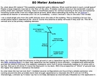 This article describe a small single wire antenna running on the side of the building allow operations on 80 meters band
 -
 The document details the optimization and construction of the _Maria Maluca_ antenna, a compact 6-band (20m-6m) directional beam. It presents a comparative analysis of shortwave antenna principles, highlighting the efficiency gains achieved by using an open feeder line and tuner as a resonant unit, contrasting this with the losses associated with traps or capacitive loads in multiband antennas. The resource specifically revisits an older South American 2-element design for 10, 15, and 20 meters, applying modern NEC-based software to develop a six-band version. Performance data is meticulously tabulated, showing impedance, free space gain, gain at 12m height, elevation angle, and front-to-back (F/B) ratio for each band from 20m through 6m. For instance, on 15m, the antenna achieves 5.1 dBd free space gain and 13.72 dB F/B ratio. The construction section provides practical guidance on element assembly using aluminum pipes and hose clamps, detailing the use of a heavy-duty glass fiber reinforced polyamide rod for electrical separation and bending strength. It also specifies the use of 450-ohm _Wireman_ line CQ 552 for the transmission line. The document includes diagrams for rod fixing, an air-wound balun, and a vertical elevation diagram for the 15m band, illustrating its DX qualification. It also discusses the antenna's suitability for portable and expedition operations, noting its compact transport dimensions (max 1.50m length, 12 lb weight) and quick assembly time (under 15 minutes). The author, Dipl.Ing. Helmut Oeller, DC6NY, is identified as a source for material kits.
 -
 Manufacturers and distributors of coaxial surge protectors, coaxial switches, insultators, HF fixed wire antennas
 -
 30/17/12 and 20/15/10-Meter Tribanders and a 40 meters inverted V wire yagi antenna
 -
 This project outlines the construction of a 3-element reversible quad antenna specifically designed for the 40-meter band. The materials required include pushup towers, pressure-treated posts, insulated wire, and various electrical components such as relays and a balun. The construction process is straightforward, beginning with the installation of the posts in a straight line, followed by the assembly of the antenna elements and their elevation to the desired height. The antenna's design allows for directional signal reception, making it ideal for operators looking to enhance their communication capabilities on the 40-meter band. The project includes detailed instructions on tuning the antenna for optimal performance, ensuring that operators can achieve the lowest SWR possible. Additionally, the design can be adapted for other bands by extrapolating dimensions, providing versatility for amateur radio enthusiasts. Overall, this reversible quad antenna project is suitable for both beginners and experienced operators, offering a practical solution for improving signal strength and directionality in 40-meter communications.
 -
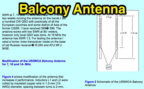 A project for a balcony antenna that works on 7 10 14 MHz made by 2 PVC tubes coiled with insulated copper wire, a solution for restricted lots.
 -
 A 90-foot vertical antenna constructed from **aluminum irrigation tubing** is detailed, focusing on its innovative raising and lowering mechanism. The resource describes a **45-foot ginpole** system, allowing a single operator to erect or lower the antenna in minutes. It covers the mechanical design, including the pivot base, insulated joints for the tubing sections, and guy wire attachment points. The antenna consists of two 30-foot sections of 4-inch tubing and one 30-foot section of 2-inch tubing, stacked with the smaller diameter at the top. The electrical design incorporates PVC "condulet" boxes at the 30-foot and 60-foot points, housing relays to change the effective height for multi-band operation on 160, 80, 40, and 30 meters. Ferrite rod inductive chokes are used for DC control and to tune out gap capacitance. The antenna is fed with 1000 feet of open wire line, connected to a matching transformer comprising stacked toroids and a coaxial/toroidal balun. Grounding is achieved with a 3x3 foot grid of 16-gauge tinned copper wires with soldered crossovers.
 -
 This antenna consists of 4 resonate dipoles made from 12 insulated copper electrical wire. The dipoles are resonate on the following bands: 6 meters, 10 meters, 12 meters and 17 meters.
 -
 AN Wireless is a manufacturer and distributor of Self Supporting Tower Systems for Wireless Communications, Wireless Internet, Wireless Networking, Microwave, Paging, Broadcast, Two-Way Radio and Amateur Radio.
 -
 The ZS6BKW antenna, a popular multiband wire antenna, offers improved band matching compared to the traditional G5RV. This construction guide details the process, beginning with specific dimensions: 13.11 meters (43 feet) for the 450-ohm ladder line and initial dipole arm lengths of approximately 14.8 meters each. It emphasizes the critical role of an _antenna analyzer_ for accurate tuning, particularly for determining the velocity factor of the ladder line and achieving a 1:1 impedance match. The article outlines the materials required, including a 1:1 current balun, 450-ohm window line, wire for the dipole arms, and a 50-ohm non-inductive resistor for testing. It provides a step-by-step procedure for cutting the ladder line to its electrical half-wavelength, explaining how to calculate the velocity factor using measured and free-space frequencies. For instance, a measured 50-ohm impedance at 12.54 MHz with a calculated free-space half-wavelength frequency of 11.44 MHz yields a velocity factor of 0.91. Final adjustments involve hoisting the antenna to its operational height and fine-tuning the dipole arm lengths to achieve optimal SWR, specifically targeting 14.200 MHz. The _ZS6BKW_ design is noted for its performance on 80m, 40m, 20m, 10m, and 6m, though it is not optimized for 15m operation. The author, _VK4MDX_, shares practical tips for durable construction using stainless steel wire and cable clamps.
 -
 Demonstrates the design and construction of a compact, portable multi-band mini-delta loop antenna, specifically optimized for /P (portable) operations from remote locations like Scottish islands. The resource covers the theoretical underpinnings of half-wave loops, contrasting closed and open configurations, and then details the application of a folded dipole principle to achieve a 50-ohm match for direct coax feed. It presents empirical formulas for calculating element lengths, considering the velocity factor of common wire types, and provides a detailed example for a 20m (14.175 MHz) version. The article includes a comprehensive table of dimensions and allowances for a five-band (20m, 17m, 15m, 12m, 10m) mini-delta beam, along with construction hints for the central support and balun. It specifies a 1:1 trifilar balun wound on a ferrite rod and describes the antenna adjustment process using an _MFJ-259B Antenna Analyser_. Initial test results indicate an SWR of 1:1 at resonance and a bandwidth of approximately 240 kHz on 20m, even at a low height of five feet above ground. The distinctive utility lies in its focus on a practical, easily deployable beam antenna for portable DXing, offering a viable alternative to more complex or larger arrays.
 -
 GW4ALG's _136 kHz Pages_ document the evolution of vertical antennas for the 2200m band, starting with a prototype mounted on a house wall. This initial design, despite achieving the first **395 km** GM-GW QSO, suffered from significant insulation breakdown, high RF losses due to proximity to the house, and difficult tuning adjustments. The author details the challenges of maintaining resonance and matching with a variometer in the loft, noting that adding three earth spikes offered no measurable improvement over a simple water tap connection. The subsequent experimental 12m vertical, relocated away from the house, significantly reduced dielectric losses and proved far more effective. This antenna enabled GW4ALG to set a world DX record on 136 kHz with a **1916 km** QSO to OH1TN, and an intra-UK record of **703 km** to GM3YXM/P. The resource further explores the use of helium-filled balloons to extend the vertical radiator, achieving heights up to 27m, typically 20m, for enhanced low-band performance. Practical advice on balloon types, inflation, and critical insulation between the wire and balloon is provided, emphasizing safety and avoiding arcing.
 -
 This online guide details the microphone pinout for the Kenwood TR-7950 transceiver, specifically addressing the wiring configuration for a dynamic mobile microphone with a **500 Ohm** impedance. It provides a pin-by-pin breakdown for the 6-pin microphone connector, identifying the function of each active pin. The resource specifies that Pin #1 is for the microphone audio (white wire), Pin #2 controls the _PTT_ (black wire), Pin #3 activates the memory down function (blue wire), and Pin #4 controls the memory up function (red wire). Pin #6 is designated as the ground connection, while Pin #5 remains unused in this configuration. The document focuses on the physical wiring necessary to restore microphone functionality to the Kenwood TR-7950, a transceiver capable of **45 watts** output on the _2m band_. It directly addresses the technical challenge of re-establishing correct electrical connections after microphone wires have been disconnected from the connector. The information facilitates proper microphone operation for simplex QSOs and other voice communications. DXZone Focus: Online Guide | Microphone Pinout | Kenwood TR-7950 | PTT Wiring
 -
 The G5RV multiband HF antenna, designed by Louis Varney (G5RV) in 1946, is a popular compromise antenna offering good overall performance on most HF bands when paired with an external antenna tuner. The basic full-size G5RV measures 102 feet across the top for 80 through 10 meter operation and is fed at the center via a 34-foot low-loss feed-stub. This interaction between the radiating section and the feed-stub facilitates matching across 80-10 meters with a standard tuner, often eliminating the need for ladder line directly to the shack. The antenna's design center frequency is 14.150 MHz, configured as a 3/2-wave dipole on 20 meters, with its 102-foot length derived from long-wire antenna formulas. Construction details emphasize the matching section, which can be open wire, ladder line (window-type), or TV twin lead. Each type has a specific velocity factor (VF) affecting its physical length for an electrical half-wave on 14 MHz; for instance, open wire requires 33.7 feet (VF 0.97), ladder line 31.3 feet (VF 0.90), and TV twin lead 28.5 feet (VF 0.82). The article provides formulas for calculating these lengths and discusses the antenna's behavior on individual bands, from 3.5 MHz where it acts as a shortened dipole, to 28 MHz where it functions as two three-half-wave long-wire antennas fed in-phase. Practical construction notes include recommendations for vertical descent of the matching section, sealing the coax junction, providing strain relief, and winding a coaxial choke coil to mitigate common mode current. The resource also presents dimensions for double-size (204 ft) and half-size (51 ft) G5RV versions, along with their corresponding matching section lengths for various line types, making it a versatile reference for hams considering this classic wire antenna.
 -
 Article on various type of transmissium medium, like parallel lines, twisted pairs, shielded pairs, coax lines
 -
 A Tribute to Morse telegraphy and resource for wire and wireless telegraph historians and key collectors
 -
 An home made vertical dipole antenna made with simple material. The antenna has a total length of aproximately 16 feet. In this article appeared on June QST 2019, the author explain how he reached the optimal confirugation changing and adjusting the lower part of the antenna, trimming and spacing correctly the copper wire. PDF File to downloas
 -
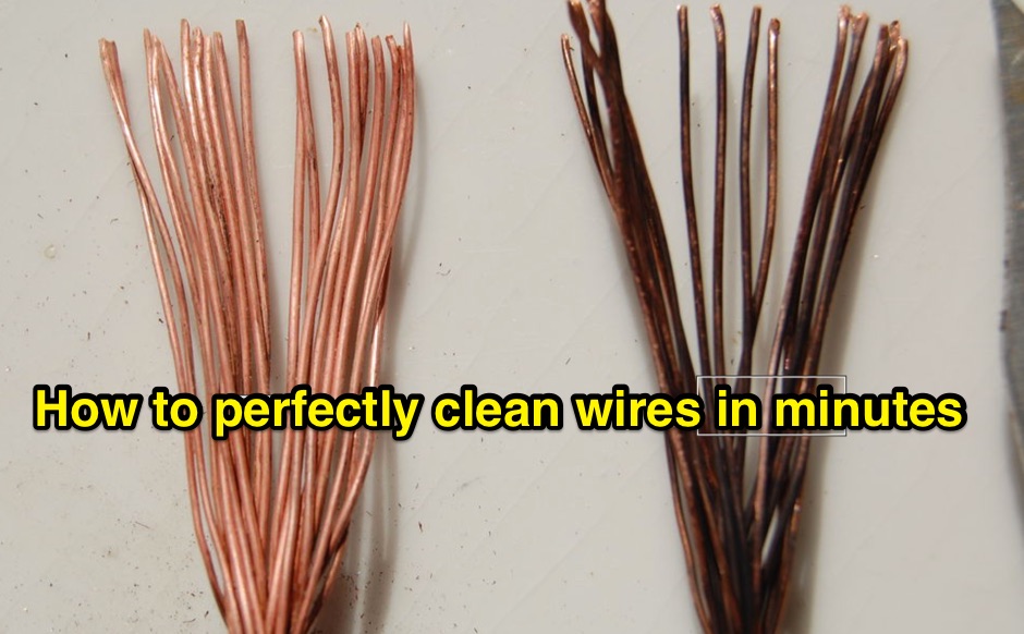 Here is an old ham radio operators trick for cleaning wires for soldering that are old and corroded. It is hard to find this technique printed anywhere!
 -
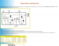 Have you problem with your RG cables ? This page describes a smart antenna box using an RG-cathode for 3 antennas. The remote control needs just a simple wire and the GND for remote-control
 -
 UK manufacturer of ham radio accessories, including TNX, SDR receivers, RF Diplexers Triplexers, bandpass filters, iambic memory keyers.
 -
 Selecting appropriate cabling for amateur radio installations, whether for antenna feedlines, control lines, or station wiring, is critical for optimal performance and safety. This resource provides access to a manufacturer specializing in a broad range of electronic and electrical cables, including options suitable for various ham radio applications. Their product line encompasses standard and custom cable solutions, designed to meet specific operational requirements for both indoor shack setups and outdoor antenna systems. The company emphasizes _proven quality_ and compliance, with products certified by the Canadian Standards Association (CSA), Underwriters Laboratories (UL), and Intertek (ETL). Their quality management system is registered to _ISO 9001:2015_, ensuring consistent product standards. They offer competitive pricing and utilize AI-logistic tools for reliable on-time delivery, serving customers globally with technical support. Access to detailed technical specifications and an online quote tool is available for registered site members, facilitating precise cable selection for projects requiring specific impedance, shielding, or environmental ratings.